Indesit KN3G21S: инструкция
Раздел: Бытовая, кухонная техника, электроника и оборудование
Тип: Плита
Инструкция к Плите Indesit KN3G21S

KN3G21S/EU
Украінська
UA
English
GB
Інструкціі з експлуатаціі
КУХНЯ
Operating Instructions
COOKER AND OVEN
Зміст
Contents
Інструкціі з експлуатаціі,1
Опис установки-Загальнии вигляд,2
Operating Instructions,1
Опис установки-Панель управління,3
Description of the appliance-Overall view,2
Встановлення,33
Description of the appliance-Control Panel,3
Включення і використання,37
Installation,4
Запобіжні засоби і поради,40
Start-up and use,8
Догляд i технічне обслуговування,41
Precautions and tips,11
Допомога,41
Care and maintenance,12
Assistance,12
Românã
Magyar
RO
HU
Instrucюiuni de folosire
Használati útmutató
ARAGAZ ЄI CUPTOR
tűzhely és a sütő
Sumar
Tartalomjegyzék
Instrucюiuni de folosire,1
Használati útmutató,1
Descrierea aparatului- Vedere de ansamblu,2
A készülék leírása- A készülék áttekintése,2
Descrierea aparatului-Panoul de control,3
A készülék leírása- Kezelőpanel,3
Instalare,13
Üzembe helyezés,42
Pornire єi utilizare, 17
Bekapcsolás és használat,47
Precauюii єi sfaturi,20
Óvintézkedések és tanácsok,50
Оntreюinere єi curгюire,21
Karbantartás és ápolás,51
Asistenюг,21
Szerviz,51
Русский
RS
PT
Português
Instruções para a utilização
Руководство по эксплуатации
FOGÃO E FORNO
КУХОННАЯ ПЛИТА С ДУХОВЫМ ШКАФОМ
Índice
Содержание
Instruções para a utilização,1
Руководство по эксплуатации,1
Descrição do aparelho-Vista de conjunto,2
Описание изделия-Общий вид,2
Descrição do aparelho-Painel de comandos,3
Описание изделия-Панель управления,3
Instalação,52
Монтаж,22
Início e utilização, 56
Включение и эксплуатация,27
Precauções e conselhos,59
Предосторожности и рекомендации,30
Manutenção e cuidados,60
Техническое обслуживание и уход,31
Assistência técnica,60
Техническое обслуживание,32
14
1
7
2
8
3
9
4
10
5
11
12
13
6
6
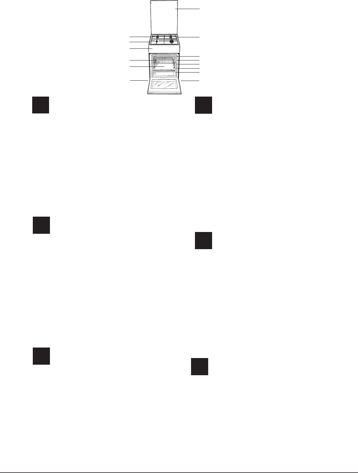
Описание изделия
Description of the appliance
GB
RS
Общий вид
Overall view
1 Hob burner
1.Газовые горелки
2 Hob Grid
2.Рабочая поверхность
3.Control panel
3.Панель управления
4.Sliding grill rack
4.Решетка духовки
5.DRIPPING pan
5.Противень или жарочный лист
6.Adjustable foot
6.Регулируемые ножки
7.Containment surface for spills
7.Электрические конфорки
8.GUIDE RAILS for the sliding racks
8.HAПPABЛЯЮЩИE для противеней решеток
9.position 5
9. Положение 1
10.position 4
10. Положение 2
11. Положение 3
11.position 3
12. Положение 4
12.position 2
13. Положение 5
13.position 1
14. Cтеклянная крышка
14.Glass Cover
Descriere aparatului
RO
Vedere de ansamblu
Опис плити
1 Arzătoare pe gaz
UA
Загальнии вигляд
2 Grătare plită
3 Panou frontal de control
1.Газовий пальник
4 Grătarul cuptorului
2.Піддон на випадок переливань
5 Tavă de coacere
3.Панель управління
6 Picioare reglabile
4.Полка РЕШІТKИ
7 Plită
5.Полка ДEКО
6.Лапка для налаштування
8 GHIDAJE alunecare rafturi
7.Пoверхня для збирання збiглoї piдини
9 nivelul 5
8.HAПPABЛЯЮЧІ для полиць
10 nivelul 4
9.положення 5
11 nivelul 3
10.положення 4
11.положення 3
12 nivelul 2
12.положення 2
13 nivelul 1
13.положення 1
14 Capacul din sticlă
14. Скляна кришка
A készülék leírása
HU
A készülék áttekintése
Descrição do aparelho
PT
1 Gáz égõ
Vista de conjunto
2 Edénytartó rács
1. Queimador a gás
3 Kapcsoló tábla
2.Grade do piano de trabalho
4 Sütõ rács
3 .Painel de comandos
5 Serpenyõ vagy sütõtepsi
4.Prateleira GRADE
6 Állítható lábacska vagy láb
5.Prateleira BANDEJA PINGADEIRA
6. Pé de regulação
7 Zsírfelfogó borítólap
7.Plano de retenção dos eventuais vazamentos
8 TÁLCASíNEK
8. GUIAS de deslizamento das prateleiras
9 helyzet 5
9.Posição 5
10 helyzet 4
10.Posição 4
11.Posição 3
11 helyzet 3
12.Posição 2
12 helyzet 2
13.Posição 1
13 helyzet 1
14.O sobretampo de vidro
14 Ha felmelegedik
2

1
GB
2
3
4
5
Опис плити
Description of the appliance
UA
GB
Панель управління
Control panel
1. Автоматичне запалювання*
1.GAS BURNER IGNITION button*
2.Сукоятка ТАЙМЕРА
2.TIMER knob
3. Ручка ДУХОВКА й гриля
3.OVEN AND GRILL CONTROL knob
4.КНОПКА РОЖНА та ОСВІТЛЕННЯ ДУХОВКИ
4.OVEN LIGHT / ROTISSERIE button
5.Ручки для керування газовими
5.Hob BURNER control knob
пальниками на варильній поверхні
*Available only on certain models
*
Є лише в деяких моделях.
Descrição do aparelho
PT
A készülék leírása
Painel de comandos
HU
Kezelőpanel
1.Acendedor electrónico dos queimadores do plano*
2.Manípulo conta-minutos
1.Gázégő gyújtási*
3.Manípulo do forno e do grill
2.Időmérő gomb
4.Manípulo luz do forno
3.Sütő és grill gomb
5.Botão luz do forno e rotisserie
4. Sütő könnyű és grillező gomb
*Presente apenas em alguns modelos
5.A tűzhely gázégőinek vezérlő gombjai
*Csak az üvegtetõs modellek esetén
Descriere aparatului
RO
Panoul de control
1.Buton pentru activarea aprinderii electronice *
2.Buton cronometru
3.Buton de comandã pentru cuptor ºi grill
4.Buton pentru activarea luminii din cuptor/ rotisserie
5.Butoane comandi ochiuri aragaz
*prezent doar la anumite modele
Описание изделия
RS
Панель управления
1.Электронное зажигание конфорок варочной панели*
2.Таймер
3.Рукоятка управления духовкой и грилем
4.Кнопка включения/выключения освещения духовки
5. Рукоятки включения газовых конфорок
варочной панели
*Имеется только в некоторых моделях.
3
Installation
! Before operating your new appliance please read
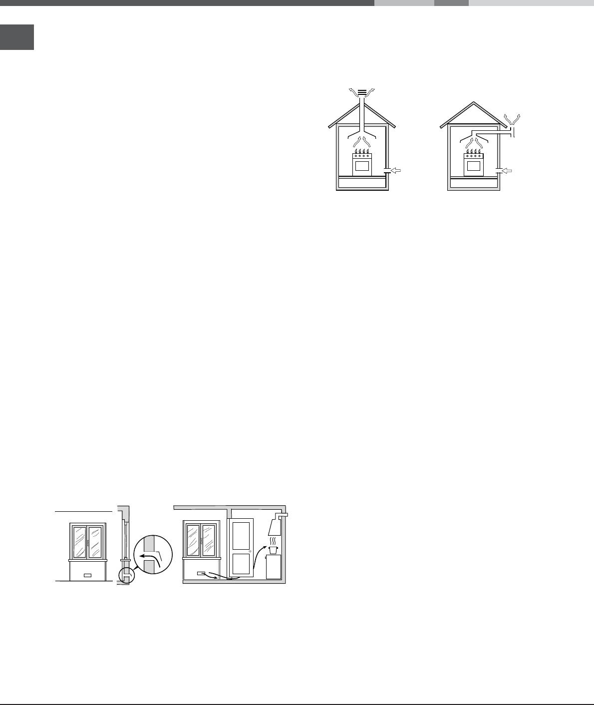
The disposal of combustion fumes should be
GB
this instruction booklet carefully. It contains important
guaranteed using a hood connected to a safe and
information concerning the safe installation and
efficient natural suction chimney, or using an electric
operation of the appliance.
fan that begins to operate automatically every time the
! Please keep these operating instructions for future
appliance is switched on (see gure).
reference. Make sure that the instructions are kept with
the appliance if it is sold, given away or moved.
! The appliance must be installed by a qualified
professional according to the instructions provided.
! Any necessary adjustment or maintenance must be
performed after the cooker has been disconnected
from the electricity supply.
! We recommend cleaning the oven before using it for
the first time, following the instructions provided in the
„Care and maintenance” section.
Fumes channelled through
a chimney or branched
Fumes channelled
flue system reserved for
Room ventilation
straight outside
cooking appliances)
The appliance may only be installed in permanently-
! The liquefied petroleum gases are heavier than air
ventilated rooms, according to current national
and collect by the floor, therefore all rooms containing
legislation. The room in which the appliance is installed
LPG cylinders must have openings leading outside so
must be ventilated adequately so as to provide as
that any leaked gas can escape easily.
much air as is needed by the normal gas combustion
LPG cylinders, therefore, whether partially or
3
process (the flow of air must not be lower than 2 m
/h
completely full, must not be installed or stored in rooms
per kW of installed power).
or storage areas that are below ground level (cellars,
The air inlets, protected by grilles, should have a duct
etc.). Only the
2
with an inner cross section of at least 100 cm
and
cylinder being used should be stored in the room; this
should be positioned so that they are not liable to even
should also be kept well away from sources
partial obstruction (see gure A).
of heat (ovens, chimneys, stoves) that may cause
These inlets should be enlarged by 100% - with a
the temperature of the cylinder to rise above 50°C.
2
minimum of 200 cm
- whenever the surface of the
hob is not equipped with a flame failure safety device.
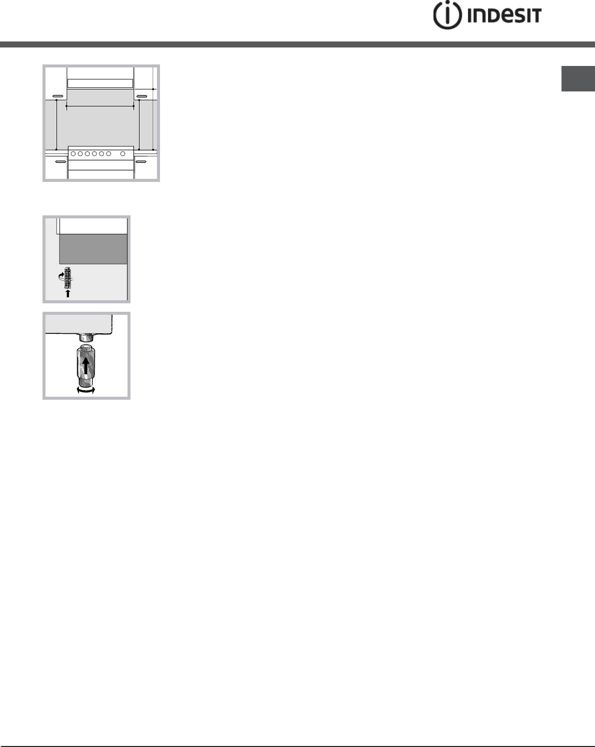
Positioning and levelling
When the flow of air is provided in an indirect manner
from adjacent rooms (see gure B), provided that these
! It is possible to install the appliance alongside
are not communal parts of a building, areas with
cupboards whose height does not exceed that of the
increased fire hazards or bedrooms, the inlets should
hob surface.
be fitted with a ventilation duct leading outside as
described above.
! Make sure that the wall in contact with the back of
Adjacent room Room requiring
the appliance is made from a non-flammable, heat-
ventilation
A B
resistant material (T 90°C).
To install the appliance correctly:
• Place it in the kitchen, dining room or the bed-sit (not
in the bathroom).
• If the top of the hob is higher than the cupboards,
A
the appliance must be installed at least 200 mm away
from them.
Ventilation opening for
Increase in the gap between
• If the cooker is installed underneath a wall cabinet,
comburent air
the door and the flooring
there must be a minimum distance of 420 mm
between this cabinet and the top of the hob.
! After prolonged use of the appliance, it is advisable to
This distance should be increased to 700 mm if the
open a window or increase the speed of any fans used.
wall cabinets are flammable (see gure).
Disposing of combustion fumes
• Do not position blinds behind the cooker or less than
200 mm away from its sides.
• Any hoods must be installed according to the
4
instructions listed in the relevant operating manual.
GB
Levelling
If it is necessary to level
the appliance, screw the
adjustable feet into the
places provided on each
corner of the base of the
cooker (see gure).
The legs* fit into the slots on the underside of the base
of the cooker.
Electrical connection
Install a standardised plug
corresponding to the load
indicated on the appliance data
plate (see Technical data table).
The appliance must be directly
connected to the mains using an
omnipolar circuit-breaker with a
minimum contact opening of 3 mm
installed between the appliance
and the mains. The circuit-breaker
must be suitable for the charge indicated and must comply
with NFC 15-100 regulations (the earthing wire must not be
interrupted by the circuit-breaker). The supply cable must
be positioned so that it does not come into contact with
temperatures higher than 50°C at any point.
Before connecting the appliance to the power supply,
make sure that:
• The appliance is earthed and the plug is compliant with
the law.
• The socket can withstand the maximum power of the
appliance, which is indicated by the data plate.
• The voltage is in the range between the values
indicated on the data plate.
• The socket is compatible with the plug of the
appliance. If the socket is incompatible with the
plug, ask an authorised technician to replace it. Do
not use extension cords or multiple sockets.
! Once the appliance has been installed, the power
supply cable and the electrical socket must be easily
accessible.
! The cable must not be bent or compressed.
! The cable must be checked regularly and replaced
5
HOOD
Min. mm.
600
mm.
420
420
mm. with hood
mm. without hood
650
700
Min.
Min. mm.
min.
min.
by authorised technicians only.
! The manufacturer declines any liability should
these safety measures not be observed.
Gas connection
Connection to the gas network or to the gas cylinder
may be carried out using a flexible rubber or steel hose,
in accordance with current national legislation and after
making sure that the appliance is suited to the type of gas
with which it will be supplied (see the rating sticker on
the cover: if this is not the case see below). When using
liquid gas from a cylinder, install a pressure regulator
which complies with current national regulations. To
make connection easier, the gas supply may be turned
sideways*: reverse the position of the hose holder with
that of the cap and replace the gasket that is supplied
with the appliance.
! Check that the pressure of the gas supply is
consistent with the values indicated in the Table
of burner and nozzle specifications (see below).
This will ensure the safe operation and durability of
your appliance while maintaining efficient energy
consumption.
Gas connection using a flexible rubber hose
Make sure that the hose complies with current national
legislation. The internal diameter of the hose must
measure: 8 mm for liquid gas supply; 13 mm for
methane gas supply.
Once the connection has been performed, make sure
that the hose:
• Does not come into contact with any parts that reach
temperatures of over 50°C.
• Is not subject to any pulling or twisting forces and
that it is not kinked or bent.
• Does not come into contact with blades, sharp
corners or moving parts and that it is not
compressed.
• Is easy to inspect along its whole length so that its
condition may be checked.
• Is shorter than 1500 mm.
• Fits firmly into place at both ends, where it will
be fixed using clamps that comply with current
regulations.
! If one or more of these conditions is not fulfilled
or if the cooker must be installed according to the
conditions listed for class 2 - subclass 1 appliances
(installed between two cupboards), the flexible steel
hose must be used instead (see below).
Connecting a flexible jointless stainless steel pipe to
* Only available in certain models
GB
6
A
V
a threaded attachment
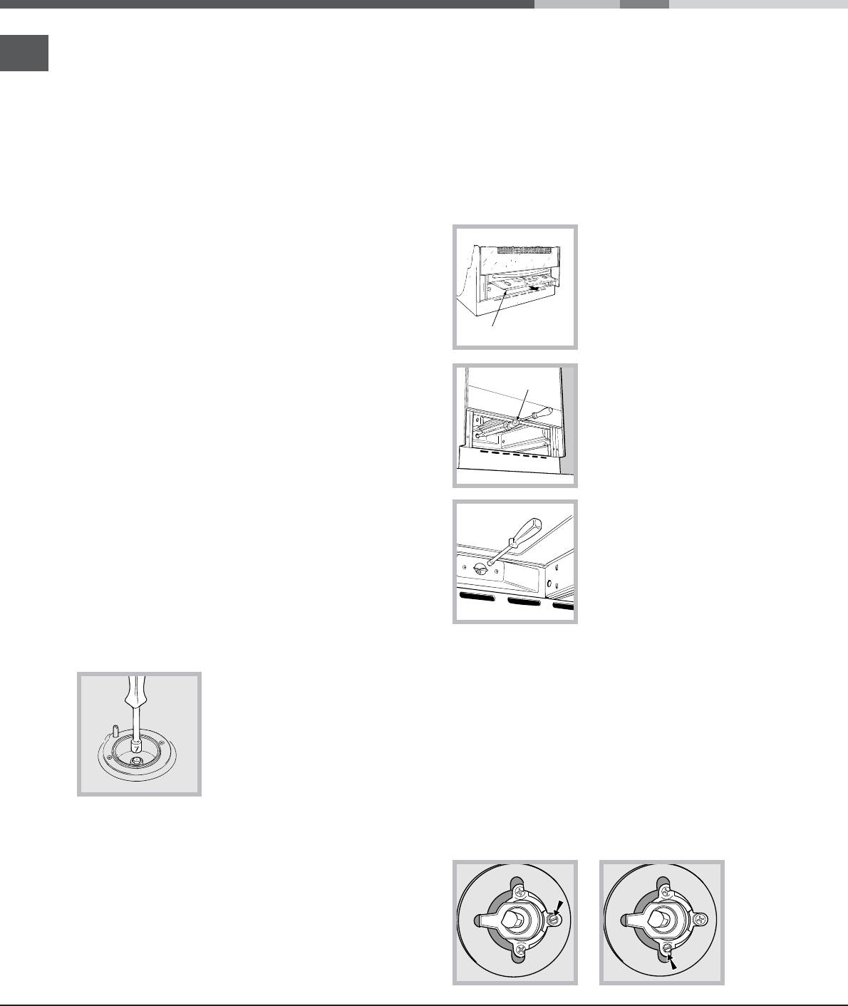
Adapting the oven
Make sure that the hose and gaskets comply with
current national legislation.
Replacing the oven burner nozzle:
To begin using the hose, remove the hose holder on the
1. Remove the oven compartment.
appliance (the gas supply inlet on the appliance is a
2. Slide out the protection panel A
cylindrical threaded 1/2 gas male attachment).
(see diagram).
! Perform the connection in such a way that the hose
length does not exceed a maximum of 2 metres,
making sure that the hose is not compressed and does
not come into contact with moving parts.
3. Remove the oven burner
Checking the connection for leaks
after unscrewing the screws V
(see gure).
When the installation process is complete, check the
The whole operation will be
hose fittings for leaks using a soapy solution. Never
made easier if the oven door is
use a flame.
removed.
Adapting to different types of gas
4. Unscrew the nozzle using a
It is possible to adapt the appliance to a type of gas
special nozzle socket spanner
other than the default type (this is indicated on the
(see gure) or with a 7 mm
rating label on the cover).
socket spanner, and replace it
with a new nozzle that is suited
Adapting the hob
to the new type of gas (see
Burner and nozzle speci cations
Replacing the nozzles for the hob burners:
table).
1. Remove the hob grids and slide the burners off their
seats.
Adjusting the gas oven
2. Unscrew the nozzles using a 7 mm socket spanner
burner’s minimum setting:
(see gure), and replace them with nozzles suited to
1. Light the burner (see Start-up
the new type of gas(see Burner and nozzle speci cations
and Use).
table).
2. Turn the knob to the
3. Replace all the components by following the above
minimum position (MIN)
instructions in reverse.
after it has been in the maximum position (MAX) for
approximately 10 minutes.
Adjusting the hob burners’
3. Remove the knob.
minimum setting:
4. Tighten or loosen the adjustment screws on the
1. Turn the tap to the minimum
outside of the thermostat pin (see gure) until the flame
position.
is small but steady.
2. Remove the knob and adjust
! If the appliance is connected to liquid gas, the
the regulatory screw, which is
adjustment screw must be fastened as tightly as
positioned inside or next to the
possible.
tap pin, until the flame is small
5. Turn the knob from the MAX position to the MIN
but steady.
position quickly or open and shut the oven door,
! If the appliance is connected to a liquid gas supply,
making sure that the burner is not extinguished.
the regulatory screw must be fastened as tightly as
possible.
3. While the burner is alight, quickly change the position of
the knob from minimum to maximum and vice versa several
times, checking that the flame is not extinguished.
! The hob burners do not require primary air
adjustment.
GB
7
S
S
A
R
We recommend cleaning the oven before using it for the
first time, following the instructions provided in the „Care
and maintenance” section.
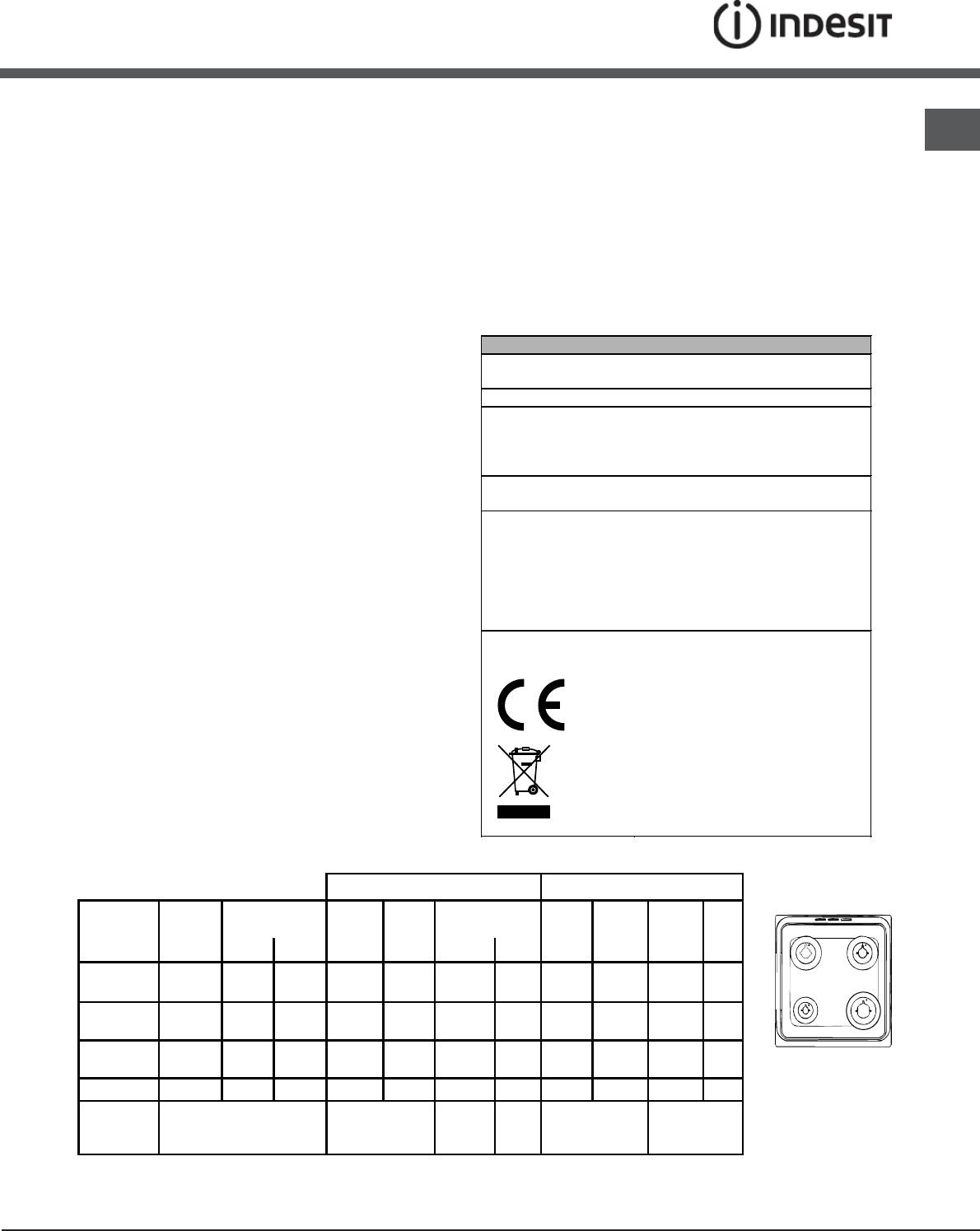
TECHNICAL DATA
Oven dimensions
34x39x44 cm
(HxWxD)
Volume
58 l
Useful
width 42 cm
measurements
depth 44 cm
relating to the oven
height 17 cm
compartment
Power supply voltage
see data plate
and frequency
may be adapted for use with any
type of gas shown on the data
plate, which is located inside the
Burners
flap or, after the oven
compartment has been opened,
on the left-hand wall inside the
oven.
EC Directives: 2006/95/EC dated
12/12/06 (Low Voltage) and
subsequent amendments -
2004/108/EC dated 15/12/04
(Electromagnetic Compatibility)
and subsequent amendments -
2009/142/EC dated 30/11/09
(Gas) and subsequent
amendments - 93/68/EEC dated
22/07/93 and subsequent
amendments - 2002/96/EC.
1275/2008 (Stand-by/ Off mode)
Table of burner and nozzle specifications
Table 1 Liquid Gas Natural Gas
Burner Diameter
Thermal Power
By-Pass
Nozzle
Flow*
Nozzle
Flow*
Nozzle
Flow*
(mm)
kW (p.c.s.*)
1/100
1/100
g/h
1/100
l/h
1/100
l/h
Nominal Reduced (mm) (mm) *** ** (mm) (mm)
Fast
100 3.00 0.7 41 87 218 214 128 286 143 286
(Large)(R)
Semi Fast
75 1.90 0.4 30 70 138 136 104 181 118 181
(Medium)(S)
Auxiliary
51 1.00 0.4 30 52 73 71 76 95 80 95
(Small)(A)
KN3G21S/EU
Oven - 2.80 1.0 46 80 204 200 119 267 132 257
Nominal (mbar)
28-30
37
20
13
Supply
Minimum (mbar)
20
25
17
6,5
Pressures
Maximum (mbar)
35
45
25
18
Оглавление
- Installation
- Start-up and use
- Precautions and tips
- Care and maintenance
- Instalare
- Pornire şi utilizare
- Precauţii şi sfaturi
- Întreţinere şi curăţire
- Установка
- Включение и эксплуатация
- Предосторожности и рекомендации
- Техническое обслуживание и уход
- Встановлення
- Включення і використання
- Запобіжні засоби и поради
- Догляд i технічне обслуговування
- Üzembe helyezés
- Bekapcsolás és használat
- Óvintézkedések és tanácsok
- Karbantartás és ápolás
- Instalação
- Início e utilização
- Precauções e conselhos
- Manutenção e cuidados

")

")

