Indesit HIM 531 EK.A: инструкция
Раздел: Кухонная техника
Тип: Духовка
Инструкция к Духовке Indesit HIM 531 EK.A
HIM 50 EK.A
HIM 506 EK.A
/2/2/2
/2/2/2
HIM 50 EK.A IX
HIM 50 EK.A IX
/2/2/2
/2/2/2
HIM 506 EK.A
HIM 537 EK.A IX
/2/2/2
/2/2/2
HIM 506 EK.A IX
HIM 531 EK.A IX
/2/2/2/2/2/2
HIM 531 EK.A
HIM 506 EK.A IX
/2/2/2/2/2/2
HIM 531 EK.A IX
HIM 537 EK.A
HIM 537 EK.A IX
English
Deutsch
GB
DE
Operating Instructions
Bedienungsanleitungen
COOKER AND OVEN
HERD UND OFEN
Contents
Inhalt
Operating Instructions,
1
Bedienungsanleitungen,
1
Description of the appliance-Overall view,
2
Beschreibung des Geräts-Übersicht,
2
Description of the appliance-Control Panel,
3
Beschreibung des Geräts-Schalttafel,
3
Installation,
4
Installation,
31
Start-up and use,
7
Inbetriebnahme und Benutzung,
34
Cooking modes,
7
Gebrauch des Ofens,
34
Using the hob,
9
Gebrauch des Kochfeldes,
36
Precautions and tips,
11
Vorsichtsmaßnahmen und Tipps,
38
Care and maintenance,
12
Pflege und Wartung,
39
Français
Ελληνικά
FR
GR
Οδηγίες χρήσης
Mode d’emploi
ΚΟΥΖΙΝΑ ΚΑΙ ΦΟΥΡΝΟΣ
CUISINIERE ET FOUR
Περιεχόμενα
Sommaire
Mode d’emploi,
Οδηγίες χρήσης,
1
1
Description de l’appareil-Vue d’ensemble,
2
Περιγραφή της συσκευής-Συνολική άποψη,
2
Description de l’appareil-Tableau de bord,
Περιγραφή της συσκευής-Πίνακας ελέγχου,
3
3
Installation,
13
Εγκατάσταση,
40
16
Εκκίνηση και χρήση,
44
Mise en marche et utilisation,
Utilisation du plan de cuisson,
16
Προγράμματα μαγειρέματος,
44
Utilisation du four,
18
Προφυλάξεις και συμβουλές,
46
Précautions et conseils,
20
Συντήρηση και φροντίδα,
48
Nettoyage et entretien,
21
Τεχνική υποστήριξη,
49
Nederland
Русский
NL
RS
Gebruiksaanwijzing
Руководство по эксплуатации
FORNUIS EN OVEN
КУХОННАЯ ПЛИТА С ДУХОВЫМ ШКАФОМ
Inhoud
Содержание
Gebruiksaanwijzing,
1
Руководство по эксплуатации,
1
Beschrijving van het apparaat-Aanzichttekening,
2
Описание изделия-Общий вид,
2
Beschrijving van het apparaat-Bedieningspaneel,
3
Описание изделия-Панель управления,
3
Installatie,
22
Монтаж,
50
Starten en gebruik,
25
Gebruik van de oven,
25
Включение и эксплуатация,
53
De kookzones,
Программы приготовления,
53
27
Предосторожности и рекомендации,
56
Voorzorgsmaatregelen en advies,
29
Техническое обслуживание и уход,
58
Onderhoud en verzorging,
30
,
Техническое обслуживание
,
59
1
1
11
4
44
55
2
2
66
66
77
3
3
88
99
Description
Beschreibung
DE
GB
of the appliance
des Gerätes
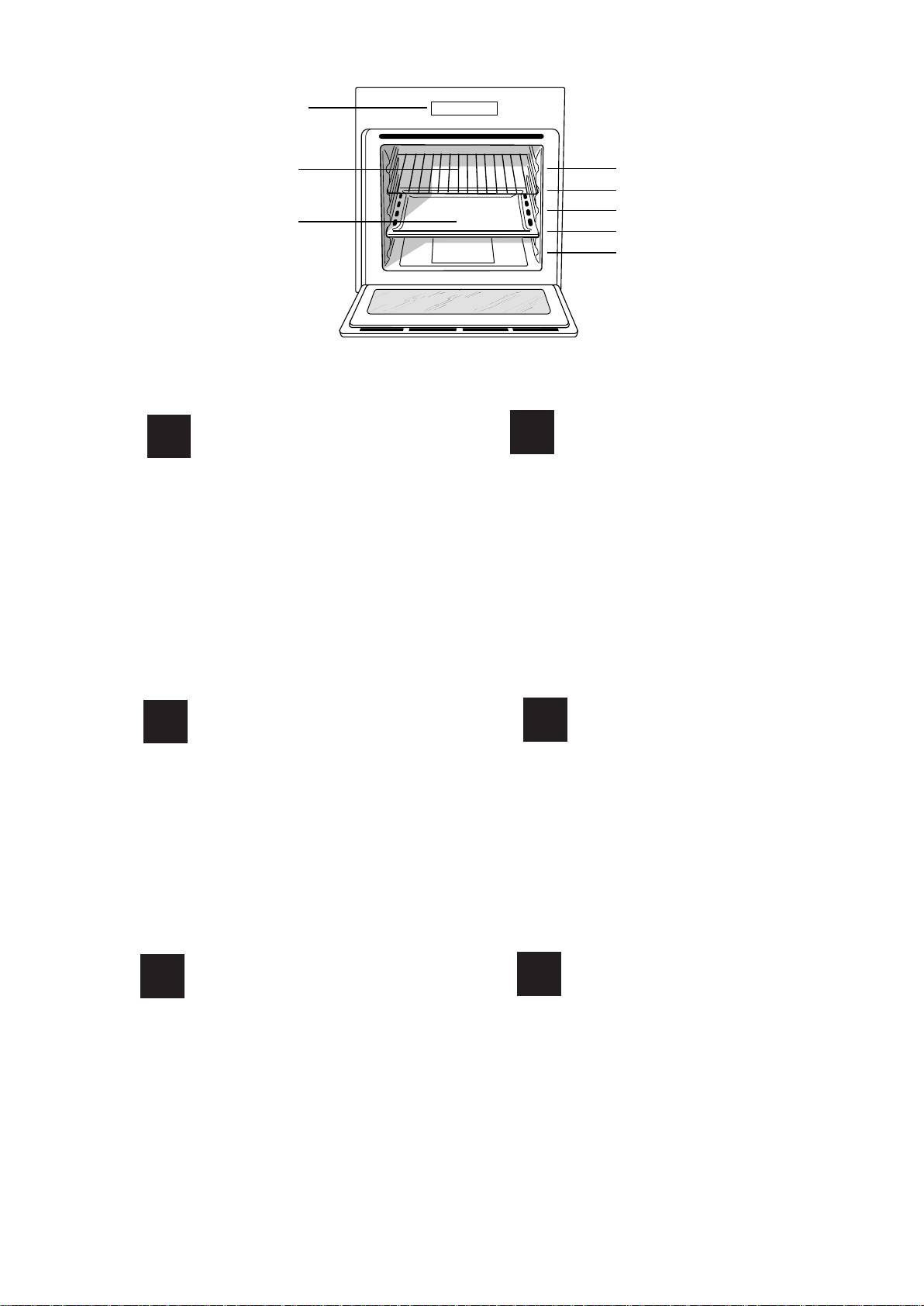
Overall view
Geräteansicht
1.Bedienfeld
1.Control panel
2.Einschub BACKOFENROST
2.Sliding grill rack
3.Einschub FETTPFANNE
3.DRIPPING pan
4.GLEITFÜHRUNGEN für die Einschübe
4.GUIDE RAILS for the sliding racks
5. position 5
5.position 5
6. position 4
6.position 4
7. position 3
7.position 3
8. position 2
8.position 2
9. position 1
9.position 1
Description
Описание изделия
Описание изделия
Описание изделия
RS
FR
de l’appareil
Общий вид
Общий вид
Общий вид
Vue d’ensemble
1.
Панель управления
Панель управления
Панель управления
Панель управления
1. Tableau de bord
2.
Решетка духовки
Решетка духовки
Решетка духовки
Решетка духовки
2. Support GRILLE
3.
Противень или жарочный лист
Противень или жарочный лист
Противень или жарочный лист
Противень или жарочный лист
3. Support LECHEFRITE
4.
HAÏPABËßÞÙÈE äëÿ ïðîòèâåíåé ðåøåòîê
HAÏPABËßÞÙÈE äëÿ ïðîòèâåíåé ðåøåòîê
HAÏPABËßÞÙÈE äëÿ ïðîòèâåíåé ðåøåòîê
HAÏPABËßÞÙÈE äëÿ ïðîòèâåíåé ðåøåòîê
4. GLISSIERES de coulissement
5.
Ïîëîæåíèå 1
Ïîëîæåíèå 1
Ïîëîæåíèå 1
Ïîëîæåíèå 1
5. niveau 5
6.
Ïîëîæåíèå 2
Ïîëîæåíèå 2
Ïîëîæåíèå 2
Ïîëîæåíèå 2
6. niveau 4
Ïîëîæåíèå 3
Ïîëîæåíèå 3
Ïîëîæåíèå 3
Ïîëîæåíèå 3
7.
7. niveau 3
8.
Ïîëîæåíèå 4
Ïîëîæåíèå 4
Ïîëîæåíèå 4
Ïîëîæåíèå 4
8. niveau 2
9.
Ïîëîæåíèå 5
Ïîëîæåíèå 5
Ïîëîæåíèå 5
Ïîëîæåíèå 5
9. niveau 1
Aanzichttekening
Περιγραφή της συσκευής
Περιγραφή της συσκευής
Περιγραφή της συσκευής
NL
GR
Aanzichttekening
Συνολική άποψη
Συνολική άποψη
Συνολική άποψη
1. Bedieningspaneel
1.
Πίνακας οργάνων
Πίνακας οργάνων
Πίνακας οργάνων
2.
Πλέγμα του φούρνου
Πλέγμα του φούρνου
Πλέγμα του φούρνου
2. Ovenrek
3.
Λιποσυλλέκτης ή πιάτο μαγειρέματος
Λιποσυλλέκτης ή πιάτο μαγειρέματος
Λιποσυλλέκτης ή πιάτο μαγειρέματος
3. Lekplaat of bakplaat
4. Geleidersvan de roosters
4.
ΟΔΗΓΟΙ ολίσθησης των επιπέοων
ΟΔΗΓΟΙ ολίσθησης των επιπέοων
ΟΔΗΓΟΙ ολίσθησης των επιπέοων
5. stand 5
5.
Θέση 5
Θέση 5
Θέση 5
6. stand 4
6.
Θέση 4
Θέση 4
Θέση 4
7. stand 3
7.
Θέση 3
Θέση 3
Θέση 3
8. stand 2
8.
Θέση 2
Θέση 2
Θέση 2
9. stand 1
9.
Θέση 1
Θέση 1
Θέση 1
2
2
3
7
1
6
4
2
3
7
1
6
4
5
Description of the appliance
GB
Beschreibung des Gerätes
DE
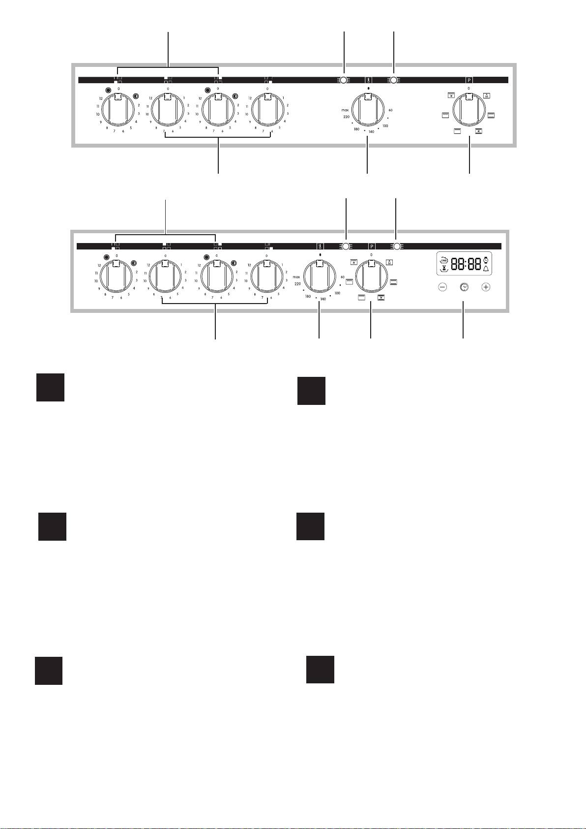
Control panel
Bedienfeld
1.Electric HOTPLATE control knob
1.Electric HOTPLATE control knob
1.Electric HOTPLATE control knob
1.Electric HOTPLATE control knob
1.
Schalter zur Einstellung der Kochfeld-Kochzonen
Schalter zur Einstellung der Kochfeld-KochzonenSchalter zur Einstellung der Kochfeld-KochzonenSchalter zur Einstellung der Kochfeld-Kochzonen
2. Electric DOUBLE HOTPLATE control knob
2. Electric DOUBLE HOTPLATE control knob
2. Electric DOUBLE HOTPLATE control knob
2. Electric DOUBLE HOTPLATE control knob
2.
Schalter zur Einstellung der Kochfeld-Kochzonen
Schalter zur Einstellung der Kochfeld-Kochzonen Schalter zur Einstellung der Kochfeld-Kochzonen Schalter zur Einstellung der Kochfeld-Kochzonen
3. ELECTRIC HOTPLATE indicator light
3. ELECTRIC HOTPLATE indicator light
3. ELECTRIC HOTPLATE indicator light
3. ELECTRIC HOTPLATE indicator light
"DOUBLE"
"DOUBLE"
3.
Betriebskontrollleuchte Elektrokochzonen
Betriebskontrollleuchte Elektrokochzonen
Betriebskontrollleuchte Elektrokochzonen
Betriebskontrollleuchte Elektrokochzonen
4. OVEN CONTROL knob
4. OVEN CONTROL knob
4. OVEN CONTROL knob
4. OVEN CONTROL knob
4.
Drehschalter des Backofens Drehschalter des BackofensDrehschalter des Backofens
5.Electronic cooking programmer
5.Electronic cooking programmer
5.Electronic cooking programmer
5.Electronic cooking programmer
*
*
*
*
5.
Elektronischer Garzeitprogrammierer
Elektronischer Garzeitprogrammierer
Elektronischer Garzeitprogrammierer
Elektronischer Garzeitprogrammierer
*
*
*
*
6.THERMOSTAT knob
6.THERMOSTAT knob
6.THERMOSTAT knob
6.THERMOSTAT knob
6.
Drehschalter THERMOSTAT
Drehschalter THERMOSTAT
Drehschalter THERMOSTAT
Drehschalter THERMOSTAT
7. THERMOSTAT indicator light
7. THERMOSTAT indicator light
7. THERMOSTAT indicator light
7. THERMOSTAT indicator light
Betriebskontrollleuchte THERMOSTAT
Betriebskontrollleuchte THERMOSTAT
Betriebskontrollleuchte THERMOSTAT
Betriebskontrollleuchte THERMOSTAT
7.
*
*
*
*
Only on certain models
Only on certain models
Only on certain models
Only on certain models
*
Nur bei einigen Modellen
Nur bei einigen Modellen
Nur bei einigen Modellen
Nur bei einigen Modellen
Aanzichttekening
Περιγραφή της συσκευής
NL
GR
Bedieningspaneel
Πίνακας ελέγχου
1. Knoppen KOOKPLATEN
1.
Επιλογείς χειρισμού των ηλεκτρικών εστιών
Επιλογείς χειρισμού των ηλεκτρικών εστιών
Επιλογείς χειρισμού των ηλεκτρικών εστιών
2.
2. Knoppen DUBBELE KOOKPLATEN
Επιλογείς χειρισμού των ηλεκτρικών εστιών
Επιλογείς χειρισμού των ηλεκτρικών εστιών
Επιλογείς χειρισμού των ηλεκτρικών εστιών
3.
3.Controlelampje WERKING KOOKPLATEN
Το
Το
Το
ενδεικτικό
ενδεικτικό
ενδεικτικό
φωτάκι
φωτάκι
φωτάκι
λειτουργίας
λειτουργίας
λειτουργίας
των
των
των
ηλεκτρικών εστιών
ηλεκτρικών εστιών
ηλεκτρικών εστιών
4.OVEN Knop
4.
Επιλογέας φούρνου
Επιλογέας φούρνου
Επιλογέας φούρνου
5.Elektronische programmering van de bereiding
*
5.
ΗΛΕΚΤΡΟΝΙΚΌ ΠΡΟΓΡΑΜΜΑΤΙΣΤHΣ
ΗΛΕΚΤΡΟΝΙΚΌ ΠΡΟΓΡΑΜΜΑΤΙΣΤHΣ
ΗΛΕΚΤΡΟΝΙΚΌ ΠΡΟΓΡΑΜΜΑΤΙΣΤHΣ
*
*
*
6.THERMOSTAATKNOP
6.
Επιλογέας
Επιλογέας
Επιλογέας
θερμοστάτη
θερμοστάτη
θερμοστάτη
7.Controlelampje THERMOSTAAT
7.
Το ενδεικτικό φωτάκι του θερμοστάτη φούρνου
Το ενδεικτικό φωτάκι του θερμοστάτη φούρνου
Το ενδεικτικό φωτάκι του θερμοστάτη φούρνου
*
Slechts op enkele modellen aanwezig
Slechts op enkele modellen aanwezigSlechts op enkele modellen aanwezigSlechts op enkele modellen aanwezig
*
Υπάρχει μόνο σε ορισμένα μοντέλα
Υπάρχει Υπάρχει
μόνο σε ορισμένα μοντέλα
μόνο σε ορισμένα μοντέλα
Описание изделия
Description de l’appareil
RS
FR
Панель управления
Tableau de bord
Рукоятки электрических конфорок
Рукоятки электрических конфорок
Рукоятки электрических конфорок
1.Manette de la plaque électrique
Manette de la plaque électrique
Manette de la plaque électrique
Manette de la plaque électrique
1.
2.Manette de la plaque électrique DOUBLES
Manette de la plaque électrique DOUBLES
Manette de la plaque électrique DOUBLES
Manette de la plaque électrique DOUBLES
2.
Рукоятки электрических конфорок
Рукоятки электрических конфорок
Рукоятки электрических конфорок
3. Voyant de fonctionnement de la plaque électrique
Voyant de fonctionnement de la plaque électrique
Voyant de fonctionnement de la plaque électrique
Voyant de fonctionnement de la plaque électrique
3.
Световой индикатор функционирования
Световой индикатор функционирования
Световой индикатор функционирования
электрических конфорок
электрических конфорок
электрических конфорок
4.Manette du four
Manette du four
Manette du four
Manette du four
4.
Рукоятка
Рукоятка
Рукоятка
выбора
выбора
выбора
функций
функций
функций
духового
духового
духового
шкафа
шкафа
шкафа
5. PROGRAMMATEUR DE CUISSON ELECTRONIQUE
PROGRAMMATEUR DE CUISSON ELECTRONIQUE
PROGRAMMATEUR DE CUISSON ELECTRONIQUE
PROGRAMMATEUR DE CUISSON ELECTRONIQUE
*
*
*
*
6.Manette du THERMOSTAT
5.
Электронные программистов
Электронные программистов
Электронные программистов
*
*
*
7. Voyant lumineux thermostat
Voyant lumineux thermostat Voyant lumineux thermostat Voyant lumineux thermostat
6.
Рукоятка выбора температуры
Рукоятка выбора температуры
Рукоятка выбора температуры
*
N’existe que sur certains modèles
N’existe que sur certains modèlesN’existe que sur certains modèlesN’existe que sur certains modèlesN’existe que sur certains modèles
7.
Световой индикатор термостата духового шкафа
Световой индикатор термостата духового шкафа
Световой индикатор термостата духового шкафа
*
*
*
Имеется только в некоторых моделях
Имеется только в некоторых моделях
Имеется только в некоторых моделях
3
! Before placing your new appliance into operation
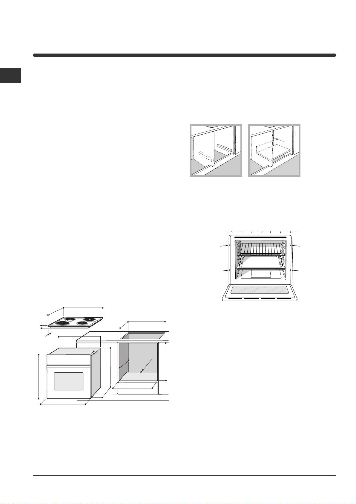
Ventilation
GB
please read these operating instructions carefully.
To ensure good ventilation, the back panel of the
They contain important information for safe use, for
cabinet must be removed. It is advisable to install the
installation and for care of the appliance.
oven so that it rests on two strips of wood, or on a
! Please keep these operating instructions for future
completely flat surface with an opening of at least 45 x
reference. Pass them on to possible new owners of
560 mm (see diagrams).
the appliance.
Positioning
! Keep packaging material out of the reach of
children. It can become a choking or suffocation
hazard (see Precautions and tips).
! The appliance must be installed by a qualified
person in compliance with the instructions provided.
Incorrect installation may cause harm to persons,
Centring and fastening
animals or may damage property.
Fitting the appliance
Secure the appliance to the cabinet by opening the
oven door and putting 4 screws into the 4 holes of
Use the appropriate cabinet to ensure that the
the outer frame.
appliance functions properly.
• The panels adjacent to the oven must be made of
heat-resistant material.
• Cabinets with a veneer exterior must be assembled
with glues which can withstand temperatures of up
to 100°C.
• To install the oven under the counter (see
diagram) and in a kitchen unit, the cabinet must
have the following dimensions:
580
500
! All parts which ensure the safe operation of the
39
appliance must not be removable without the aid of a
+4 -0
560
+4 -0
480
tool.
555
15
min
547 min
min
23
45
572
575-585
595
558
min
543543545
595
! The appliance must not come into contact with
electrical parts once it has been installed.
The consumption indications on the data plate have
been calculated for this type of installation.
45 mm.
560 mm.
Installation
4
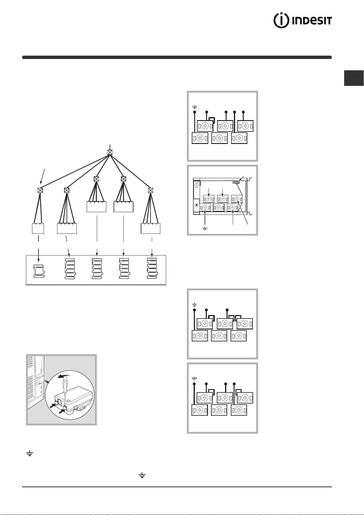
Electrical connections
The terminal board is designed for a 400 V three-
phase connection (see diagrams below).
GB
The cooker must be connected to the mains
electricity supply. It is designed to operate with
400V 3N~H05RR-F
alternating current at the voltage and frequency
5x2.5 CEI-UNEL 35363
NL1L3L2
indicated on the data plate (see the following page).
The hob is connected to the cooker using a special
5
3
1
connector.
4
2
BUILT-IN HOB
Only on
certain models
P
N
L1
L2
L3
WHITE RED YELLOWBLUE GREEN
If the electrical system has other characteristics (see
diagrams below), carry out the electrical connection
using the connection supports provided in the box
P.
BUILT-IN COOKER
230V ~H05RR-F 3x4
CEI-UNEL 35363
Replace the metal protection after performing all the
NL
necessary hob connections. If the hob is removed
5
3
1
from its position, the red cap which was originally
protecting the red connector must be replaced.
4
2
Fitting the power supply cable
1. Open the terminal
board by inserting a
400V 2N~H05RR-F 4x4
screwdriver into the
CEI-UNEL 35363
side tabs of the cover.
NL1L2
Use the screwdriver as
5
3
1
a lever by pushing it
down to open the cover
4
2
(see diagram).
2. Install the power supply cable by loosening the
cable clamp screw and the wire contact screws L-N-
3. Secure the power supply cable by fastening the
. Connect the wires to the corresponding
clamp screw.
terminals: the Blue wire to the terminal marked (N),
4. Close the cover of the terminal board.
the Brown wire to the terminal marked (L) and the
Yellow Green wire to the terminal marked
.
5
Connecting the supply cable to the mains
! Once the appliance has been installed, the power
GB
supply cable and the electrical socket must be easily
Install a standardised plug corresponding to the load
accessible.
indicated on the data plate (see side).
The appliance must be directly connected to the
! The cable must not be bent or compressed.
mains using an omnipolar circuit-breaker with a
minimum contact opening of 3 mm installed between
! The cable must be checked regularly and replaced
the appliance and the mains, suitable for the load
by authorised technicians only (see Assistance).
indicated and complying with current electrical
regulations (the earthing wire must not be interrupted
! The manufacturer declines any liability should
by the circuit-breaker). The supply cable must not
these safety measures not be observed.
come into contact with surfaces with temperatures
higher than 50°C.
! The installer must ensure that the correct electrical
connection has been made and that it is compliant
with safety regulations.
Before connecting to the power supply, make sure that:
• The appliance is earthed and the plug is compliant
with the law.
• The socket can withstand the maximum power of
the appliance, which is indicated on the data plate
(see below).
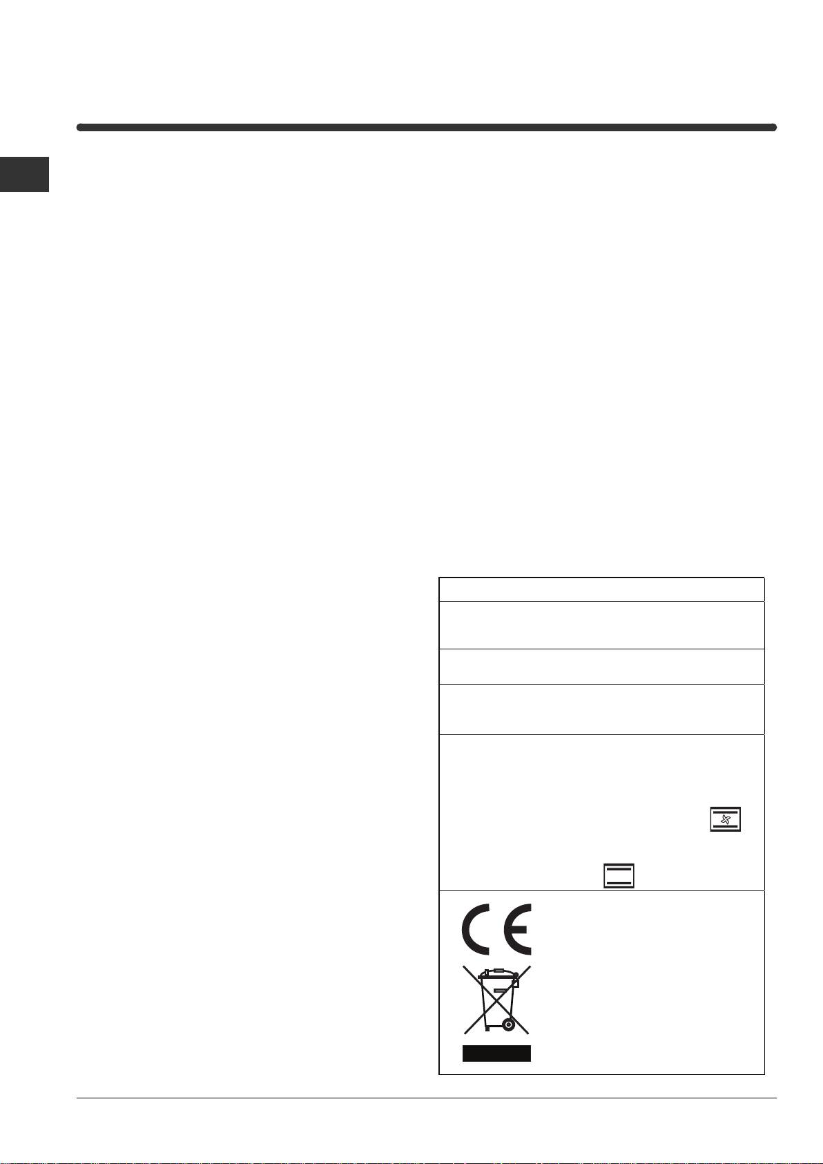
DATA PLATE
• The voltage must be in the range between the
width 43.5 cm
values indicated on the data plate (see below).
Dimensions
height 32 cm
depth 40 cm
• The socket is compatible with the plug of the
Volume lt. 56
appliance. If the socket is incompatible with the
plug, ask an authorised technician to replace it. Do
Electrical
voltage: 230V/400V~ 3N 50/60Hz
not use extension cords or multiple sockets.
connections
maximum power absorbed 9450W
Directive 2002/40/EC on the label
of electric ovens.
Standard EN 50304
Energy consumption for Forced
ENERGY LABEL
convection heating mode:
Multi-cooking
Declared energy consumption for
Natural convection Class heating
mode: Convection
This appliance conforms to the
following European Economic
Community directives:
- 2006/95/EEC of 12/12/06 (Low
Voltage) and subsequent
amendments;
- 2004/108/EEC of 15/12/04
(Electromagnetic Compatibility) and
subsequent amendments;
- 93/68/EEC of 22/07/93 and
subsequent amendments.
- 2002/96/EC and subsequent
amendments.
6
Оглавление
- Installation
- Start-up and use
- Cooking modes
- Hob
- The electronic cooking programmer
- Precautions and tips
- Maintenance and care
- Installation
- Mise en marche et utilisation
- Programmes
- Table de cuisson
- Le programmateur de cuisson électronique
- Précautions et conseils
- Nettoyage et entretien
- Het installeren
- Starten en gebruik
- Programma’s
- Kookplaat
- De elektronische programmeur
- Voorzorgsmaatregelen en advies
- Onderhoud en verzorging
- Installation
- Inbetriebsetzung und Gebrauch
- Programme
- Kochfeld
- Der elektronische Garprogrammierer
- Vorsichtsmaßregeln und Hinweise
- Reinigung und Pflege
- ÅãêáôÜóôáóç
- Åêêßíçóç êáé ÷ñÞóç
- ÐñïãñÜììáôá
- Åðßðåäï øçóßìáôïò
- Ï çëåêôñïíéêüò ðñïãñáììáôéóôÞò
- ÐñïöõëÜîåéò êáé óõìâïõëÝò
- ÓõíôÞñçóç êáé öñïíôßäá
- Монтаж
- Включение и эксплуатация
- Программы
- Варочная панель,
- Электронный таймер программирования выпечки
- Предосторожности и рекомендации
- Техническое обслуживание и уход
