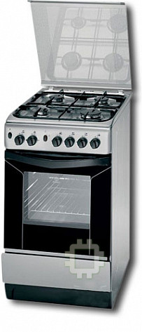
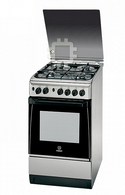
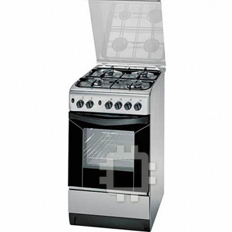
Indesit K 1G21 X: инструкция
Раздел: Бытовая, кухонная техника, электроника и оборудование
Тип: Газовая Плита
Характеристики, спецификации
Инструкция к Газовой Плите Indesit K 1G21 X
Operating Instructions
COOKER
GB
Contents
RS UAGB
Installation, 2-5
Украінська, 24
English,1
РУССКИЙ,12
Positioning and levelling
Electrical connections
Gas connection
ET
LT
LV
Adapting to different types of gas
Technical data
Lietuviu; 35
Latviešu, 46
Eesti keeles, 57
Table of burner and nozzle specifications
Description of the appliance, 6
Overall view
Control panel
Start-up and use, 7-9
Using the hob
KN1G21/UA
Using the oven
Oven cooking advice table
KN1G21S/UA
Precautions and tips, 10
General safety
Disposal
Respecting and conserving the environment
Maintenance and care, 11
Switching the appliance off
Cleaning the appliance
Gas tap maintenance
Replacing the oven light bulb
Assistance
Installation
! Before operating your new appliance please read
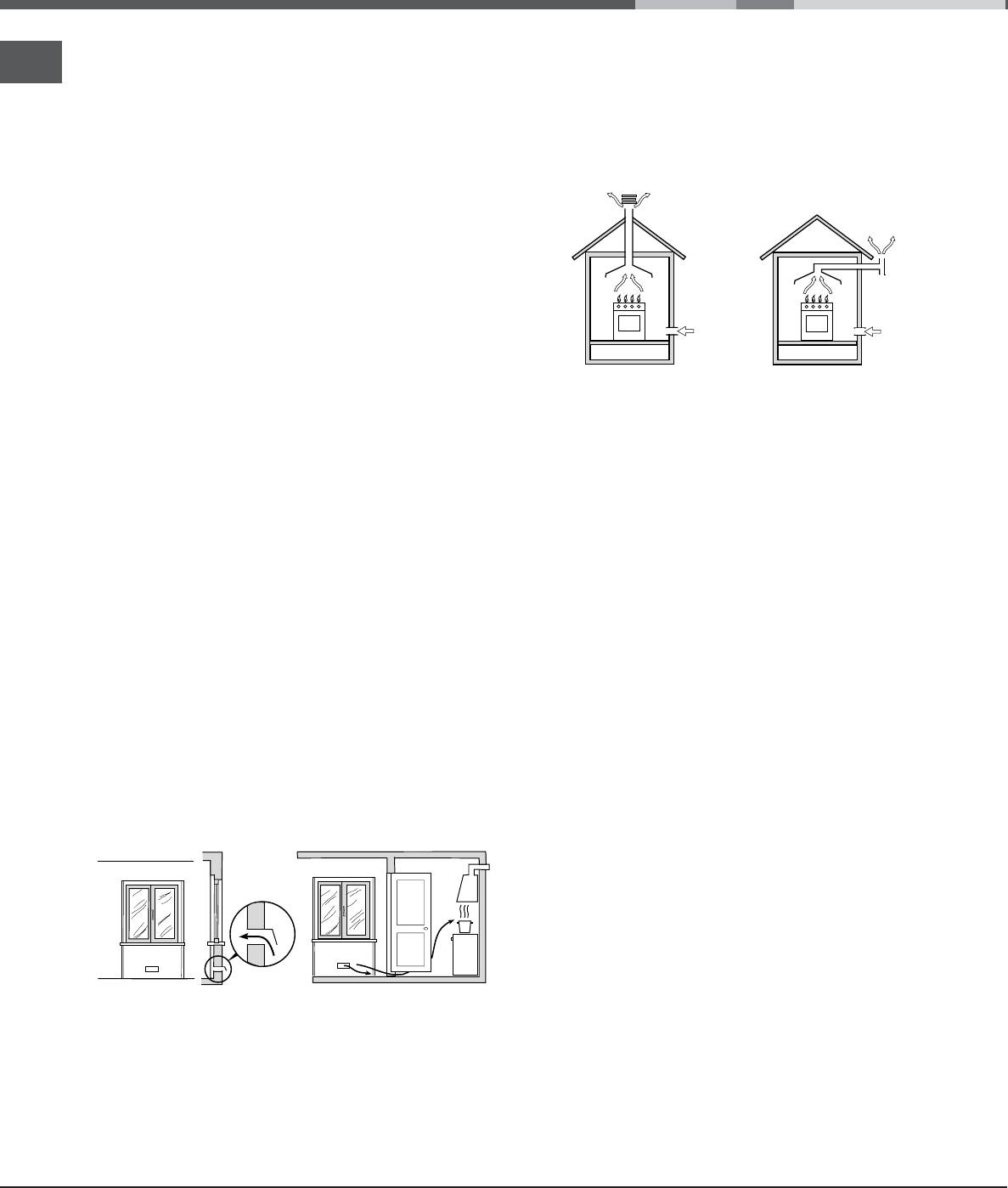
Disposing of combustion fumes
GB
this instruction booklet carefully. It contains
important information concerning the safe installation
The disposal of combustion fumes should be
and operation of the appliance.
guaranteed using a hood connected to a safe and
! Please keep these operating instructions for future
efficient natural suction chimney, or using an electric
reference. Make sure that the instructions are kept
fan that begins to operate automatically every time
with the appliance if it is sold, given away or moved.
the appliance is switched on (
see figure
).
! The appliance must be installed by a qualified
professional according to the instructions provided.
! Any necessary adjustment or maintenance must be
performed after the cooker has been disconnected
from the electricity supply.
! We recommend cleaning the oven before using it
for the first time, following the instructions provided
in the "Care and maintenance" section.
Room ventilation
Fumes channelled
Fumes channelled through
straight outside
a chimney or branched
The appliance may only be installed in permanently-
flue system reserved for
ventilated rooms, according to current national
cooking appliances)
legislation. The room in which the appliance is
! The liquefied petroleum gases are heavier than air
installed must be ventilated adequately so as to
and collect by the floor, therefore all rooms
provide as much air as is needed by the normal gas
containing LPG cylinders must have openings
combustion process (the flow of air must not be
leading outside so that any leaked gas can escape
3
lower than 2 m
/h per kW of installed power).
easily.
The air inlets, protected by grilles, should have a
LPG cylinders, therefore, whether partially or
2
duct with an inner cross section of at least 100 cm
completely full, must not be installed or stored in
and should be positioned so that they are not liable
rooms or storage areas that are below ground level
to even partial obstruction (
see figure A
).
(cellars, etc.). Only the
These inlets should be enlarged by 100% - with a
cylinder being used should be stored in the room;
2
minimum of 200 cm
- whenever the surface of the
this should also be kept well away from sources
hob is not equipped with a flame failure safety
of heat (ovens, chimneys, stoves) that may cause
device. When the flow of air is provided in an
the temperature of the cylinder to rise above 50°C.
indirect manner from adjacent rooms (
see figure B
),
provided that these are not communal parts of a
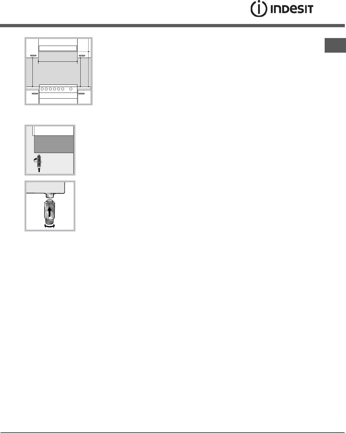
Positioning and levelling
building, areas with increased fire hazards or
bedrooms, the inlets should be fitted with a
! It is possible to install the appliance alongside
ventilation duct leading outside as described above.
cupboards whose height does not exceed that of the
Adjacent room Room requiring
hob surface.
ventilation
AB
! Make sure that the wall in contact with the back of
the appliance is made from a non-flammable, heat-
resistant material (T 90°C).
To install the appliance correctly:
A
• Place it in the kitchen, dining room or the bed-sit
(not in the bathroom).
Ventilation opening for
Increase in the gap between
• If the top of the hob is higher than the cupboards,
comburent air
the door and the flooring
the appliance must be installed at least 200 mm
away from them.
! After prolonged use of the appliance, it is
• If the cooker is installed underneath a wall cabinet,
advisable to open a window or increase the speed of
there must be a minimum distance of 420 mm
any fans used.
between this cabinet and the top of the hob.
This distance should be increased to 700 mm if
the wall cabinets are flammable (
see figure
).
2
• Do not position
! Once the appliance has been installed, the power
GB
HOOD
blinds behind the
supply cable and the electrical socket must be
cooker or less than 200
easily accessible.
Min. mm.
600
mm away from its
mm.
sides.
! The cable must not be bent or compressed.
420
420
mm. with hood
mm. without hood
• Any hoods must be
650
700
Min.
Min. mm.
min.
! The cable must be checked regularly and replaced
min.
installed according to
the instructions listed in
by authorised technicians only.
the relevant operating
manual.
! The manufacturer declines any liability should
these safety measures not be observed.
Levelling
Gas connection
If it is necessary to level the
appliance, screw the
Connection to the gas network or to the gas cylinder
adjustable feet into the places
may be carried out using a flexible rubber or steel
provided on each corner of the
hose, in accordance with current national legislation
base of the cooker (
see
and after making sure that the appliance is suited to
figure
).
the type of gas with which it will be supplied (see the
rating sticker on the cover: if this is not the case
see
below
). When using liquid gas from a cylinder, install a
The legs* fit into the slots on
pressure regulator which complies with current national
the underside of the base of
regulations. To make connection easier, the gas
the cooker.
supply may be turned sideways*: reverse the position
of the hose holder with that of the cap and replace the
gasket that is supplied with the appliance.
! Check that the pressure of the gas supply is
consistent with the values indicated in the Table of
Electrical connection
burner and nozzle specifications (
see below
). This
Install a standardised plug corresponding to the
will ensure the safe operation and durability of your
load indicated on the appliance data plate (
see
appliance while maintaining efficient energy
Technical data table
).
consumption.
The appliance must be directly connected to the mains
using an omnipolar circuit-breaker with a minimum
Gas connection using a flexible rubber hose
contact opening of 3 mm installed between the
Make sure that the hose complies with current
appliance and the mains. The circuit-breaker must be
national legislation. The internal diameter of the hose
suitable for the charge indicated and must comply with
must measure: 8 mm for liquid gas supply; 13 mm
NFC 15-100 regulations (the earthing wire must not be
for methane gas supply.
interrupted by the circuit-breaker). The supply cable
must be positioned so that it does not come into
Once the connection has been performed, make
contact with temperatures higher than 50°C at any point.
sure that the hose:
Before connecting the appliance to the power
• Does not come into contact with any parts that
supply, make sure that:
reach temperatures of over 50°C.
• The appliance is earthed and the plug is compliant
• Is not subject to any pulling or twisting forces and
with the law.
that it is not kinked or bent.
• The socket can withstand the maximum power of
• Does not come into contact with blades, sharp
the appliance, which is indicated by the data plate.
corners or moving parts and that it is not
• The voltage is in the range between the values
compressed.
indicated on the data plate.
• Is easy to inspect along its whole length so that
• The socket is compatible with the plug of the
its condition may be checked.
appliance. If the socket is incompatible with the
• Is shorter than 1500 mm.
plug, ask an authorised technician to replace it.
• Fits firmly into place at both ends, where it will be
Do not use extension cords or multiple sockets.
fixed using clamps that comply with current
* Only available in certain models
regulations.
3
! If one or more of these conditions is not fulfilled or
3. While the burner is alight, quickly change the position
GB
if the cooker must be installed according to the
of the knob from minimum to maximum and vice versa
conditions listed for class 2 - subclass 1 appliances
several times, checking that the flame is not
(installed between two cupboards), the flexible steel
extinguished.
hose must be used instead (
see below
).
! The hob burners do not require primary air adjustment.
Connecting a flexible jointless stainless steel pipe
to a threaded attachment
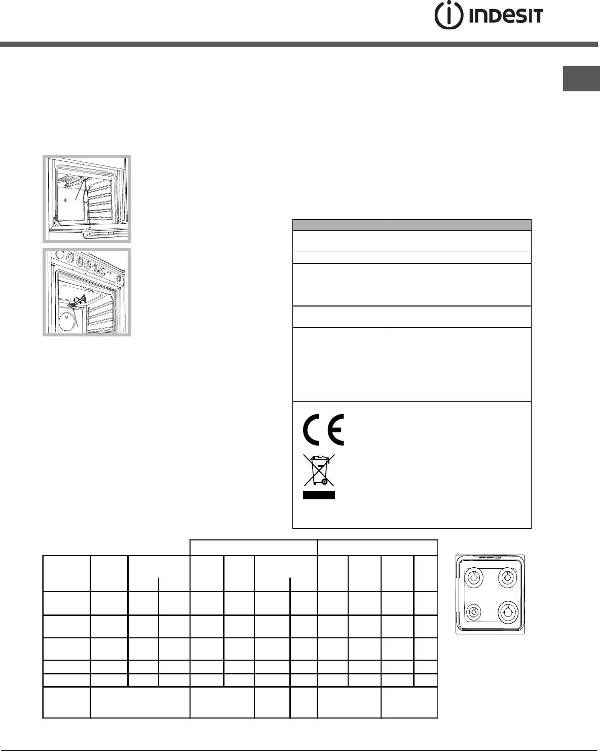
Adapting the oven
Make sure that the hose and gaskets comply with
Replacing the oven burner nozzle:
current national legislation.
1. Remove the oven compartment.
To begin using the hose, remove the hose holder on the
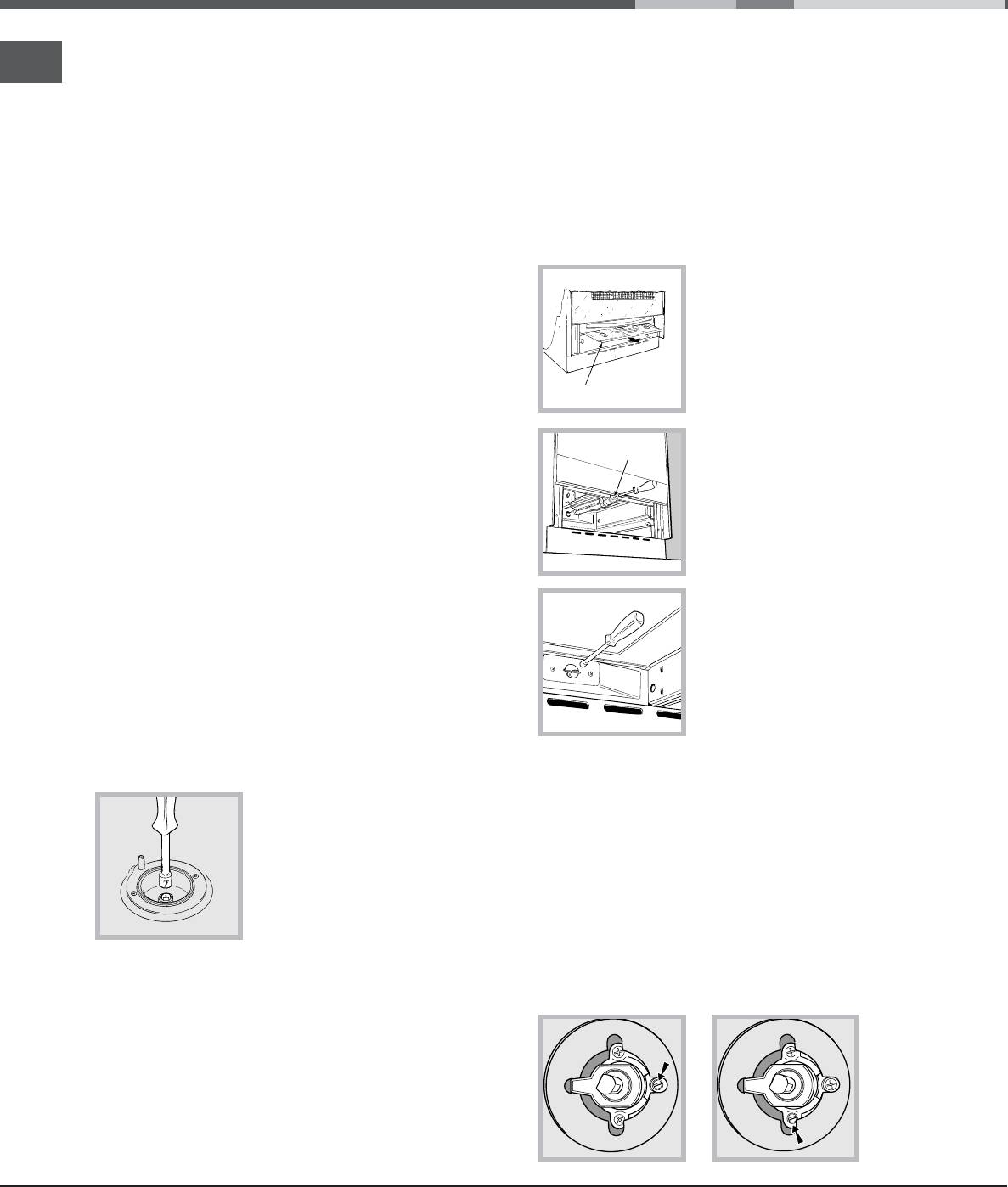
2. Slide out the protection
appliance (the gas supply inlet on the appliance is a
panel A
cylindrical threaded 1/2 gas male attachment).
(
see diagram
).
! Perform the connection in such a way that the hose
length does not exceed a maximum of 2 metres,
making sure that the hose is not compressed and
A
does not come into contact with moving parts.
3. Remove the oven burner
Checking the connection for leaks
V
after unscrewing the screws V
(
see figure
).
When the installation process is complete, check
The whole operation will be
the hose fittings for leaks using a soapy solution.
made easier if the oven door
Never use a flame.
is removed.
Adapting to different types of gas
4. Unscrew the nozzle using a
It is possible to adapt the appliance to a type of gas
special nozzle socket spanner
other than the default type (this is indicated on the
(
see figure
) or with a 7 mm
rating label on the cover).
socket spanner, and replace it
with a new nozzle that is
Adapting the hob
suited to the new type of gas
(
see Burner and nozzle
Replacing the nozzles for the hob burners:
specifications table
).
1. Remove the hob grids and slide the burners off
their seats.
Adjusting the gas oven burner’s minimum setting:
2. Unscrew the nozzles using a
1. Light the burner (
see Start-up and Use
).
7 mm socket spanner (
see
2. Turn the knob to the minimum position (MIN) after
figure
), and replace them with
it has been in the maximum position (MAX) for
nozzles suited to the new type
approximately 10 minutes.
of gas(
see Burner and nozzle
3. Remove the knob.
specifications table
).
4. Tighten or loosen the adjustment screws on the
3. Replace all the components
outside of the thermostat pin (
see figure
) until the
by following the above
flame is small but steady.
instructions in reverse.
! If the appliance is connected to liquid gas, the
adjustment screw must be fastened as tightly as
Adjusting the hob burners’ minimum setting:
possible.
1. Turn the tap to the minimum position.
2. Remove the knob and adjust the regulatory
screw, which is positioned inside or next to the tap
pin, until the flame is small but steady.
! If the appliance is connected to a liquid gas
supply, the regulatory screw must be fastened as
tightly as possible.
4
5. Turn the knob from the MAX position to the MIN
We recommend cleaning the oven before using it for the
GB
position quickly or open and shut the oven door,
first time, following the instructions provided in the
making sure that the burner is not extinguished.
"Care and maintenance" section.
Adapting the grill
Replacing the grill burner nozzle:
1. Remove the oven burner
after loosening screw V (
see
figure
).
V
TECHNICAL DATA
Oven dimensions
34x39x44 cm
(HxWxD)
2. Unscrew the grill burner
Volume
58 l
nozzle using a special nozzle
Useful
socket spanner (
see figure
) or
width 42 cm
measurements
depth 44 cm
preferably with a 7 mm socket
relating to the oven
height 18 cm
spanner, and replace it with a
compartment
new nozzle that is suited to the
Power supply voltage
see data plate
and frequency
new type of gas (
see Burner
I
may be adapted for use with any
and nozzle specifications table
).
type of gas shown on the data
! Be careful of the spark plug wires and the
plate, which is located inside the
thermocouple tubes.
Burners
flap or, after the oven
! The oven and grill burners do not require primary
compartment has been opened,
air adjustment.
on the left-hand wall inside the
! After adjusting the appliance so it may be used
oven.
with a different type of gas, replace the old rating
EC Directives: 2006/95/EC dated
12/12/06 (Low Voltage) and
label with a new one that corresponds to the new
subsequent amendments -
type of gas (these labels are available from
2004/108/EC dated 15/12/04
Authorised Technical Assistance Centres).
(Electromagnetic Compatibility)
! Should the gas pressure used be different (or vary
and subsequent amendments -
slightly) from the recommended pressure, a suitable
2009/142/EC dated 30/11/09
pressure regulator must be fitted to the inlet hose in
(Gas) and subsequent
accordance with current national regulations relating
amendments - 93/68/EEC dated
22/07/93 and subsequent
to “regulators for channelled gas”.
amendments - 2002/96/EC.
1275/2008 (Stand-by/ Off mode)
Table of burner and nozzle specifications
Table 1 Liquid Gas Natural Gas
Burner Diameter
Thermal Power
By-Pass
Nozzle
Flow*
Nozzle
Flow*
Nozzle
Flow*
(mm)
kW (p.c.s.*)
1/100
1/100
g/h
1/100
l/h
1/100
l/h
Nominal Reduced (mm) (mm) *** ** (mm) (mm)
S
S
Fast
100 3.00 0.7 41 86 218 214 116 286 143 286
A
R
(Large)(R)
Semi Fast
75 1.90 0.4 30 70 138 136 106 181 118 181
(Medium)(S)
Auxiliary
55 1.00 0.4 30 50 73 71 79 95 80 95
(Small)(A)
KN1G21/UA
Oven - 2.80 1.0 46 80 204 200 119 267 132 257
KN1G21S/UA
Grill - 2.30 - - 75 167 164 114 219 139 227
Nominal (mbar)
28-30
37
20
13
Supply
Minimum (mbar)
20
25
17
6,5
Pressures
Maximum (mbar)
35
45
25
18
At 15°C and 1013 mbar- dry gas
*** Butane P.C.S. = 49,47 MJ/Kg
3
** Propane P.C.S. = 50,37 MJ/Kg
Natural P.C.S. = 37,78 MJ/m
5
Оглавление
- Operating Instructions
- Installation
- Description of the appliance
- Start-up and use
- Precautions and tips
- Care and maintenance
- Руководство по эксплуатации
- Установка
- Описание изделия
- Включение и эксплуатация
- Предосторожности и рекомендации
- Техническое обслуживание и уход
- Інструкціі з експлуатаціі
- Встановлення
- Опис плити
- Включення і використання
- Запобіжні засоби и поради
- Догляд i технічне обслуговування
- Naudojimo instrukcijos
- Montavimas
- Prietaiso aprašymas
- Įjungimas ir naudojimas
- Atsargumo priemonės ir patarimai
- Priežiūra
- Lietođanas instrukcija
- Ierîkođana
- Ierîces apraksts
- Ieslçgđana un lietođana
- Piesardzîbas pasâkumi un ieteikumi
- Tehniskâ apkope un tîrîđana
- Kasutusjuhend
- Paigaldamine
- Seadme kirjeldus
- Käitamine ja kasutamine
- Ettevaatusabinőud ja soovitused
- Hooldus


