Asus V2-AE1: Internal components Selecting the voltage
Internal components Selecting the voltage: Asus V2-AE1
Table of contents
- Front panel features Rear panel features
- Internal components Selecting the voltage
- Removing the side cover and front panel assembly Installing a CPU
- Installing the CPU fan and heatsink assembly
- Installing a DIMM Installing an expansion card
- Installing storage drives
- Removing the bay covers and reinstalling the front panel assembly and side cover
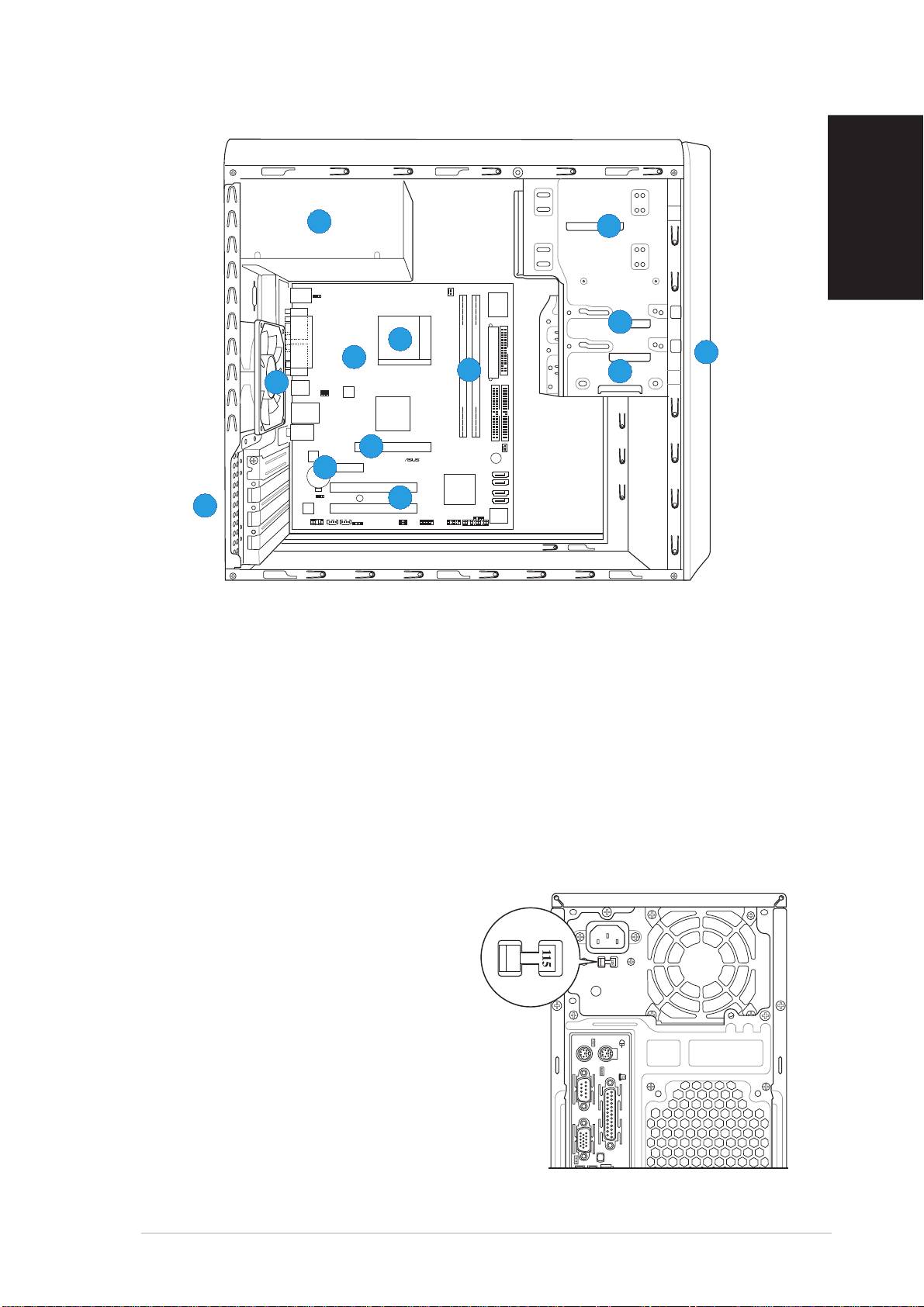
Internal components
55
55
5
22
22
2
English
PS/2KBMS
T: Mouse
KBPWR
B: Keyboard
CPU_FAN
Super
I/O
COM1
33
33
3
66
66
6
PARALLEL PORT
Socket 939
11
11
1
88
88
8
EATXPWR
VGA
77
77
7
FLOPPY
44
44
4
99
99
9
USB12
USBPW12
USBPW34
ATX12V
DDR DIMM_A1 (64 bit,184-pin module)
DDR DIMM_B1 (64 bit,184-pin module)
LAN_USB34
VIA
K8M800
Top:Line In
Center:Line Out
Below:Mic In
PRI_IDE
SEC_IDE
CHA_FAN
1010
1010
10
AGP
RTL8201CL
PCIEX1
BUZZER
CR2032 3V
11
11
1
11
Lithium Cell
11
1
SATA 2
CMOS Power
A8V-MQ
SATA 1
PCI1
VIA
VT8251
SATA 4
CLRTC
SB_PWR
11
11
1
22
22
2
SATA 3
11
11
1
33
33
3
ALC653
PCI2
CHASSIS
BIOS
PANEL
Flash
FP_AUDIO
AUX CD
SPDIF
USBPW56
USBPW78
ROM
USB56
USB78
1. Front panel cover
8. ASUS motherboard
2. 5.25-inch optical drive bays
9. Chassis fan
3. Hard disk drive bay
10. AGP slot
4. Floppy disk drive bay
11. PCI Express x1 slot
5. Power supply unit
12. PCI slots
6. CPU socket
13. Metal bracket lock
7. DIMM sockets
Selecting the voltage
The system’s power supply unit has a
115 V/230 V voltage selector switch
located beside the power connector.
Use this switch to select the
appropriate system input voltage
according to the voltage supply in your
area.
If the voltage supply in your area is
100-127 V, set the switch to 115 V.
If the voltage supply in your area is
200-240 V, set the switch to 230 V.
Quick installation guideQuick installation guide
Quick installation guideQuick installation guide
Quick installation guide
33
33
3
