Asus P1-PH1: instruction
Class: Household, kitchen appliances, electronics and equipment
Type: Computer
Manual for Asus P1-PH1
Table of contents
- Front panel features Rear panel features
- Internal components Removing the cover
- Removing the front panel cover Removing the storage drive assembly Removing the CPU fan and heatsink
- Installing the CPU Installing a DIMM
- Installing an expansion card Installing optical and storage drives
- Reinstalling the storage drive assembly Installing the foot stand
- Reinstalling the front panel cover Reinstalling the cover
English
Pundit P1-PH1
Barebone System
Quick Installation Guide
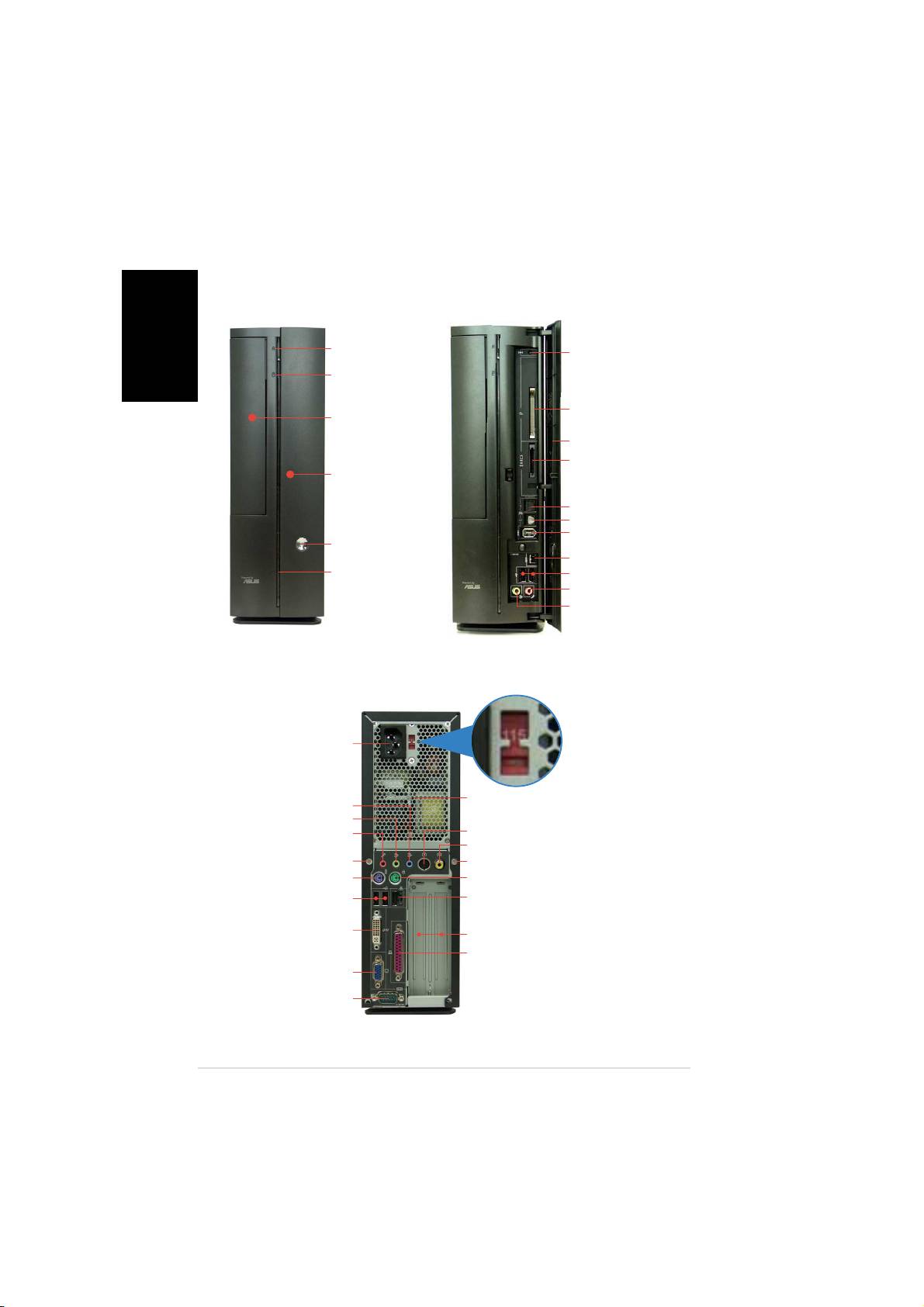
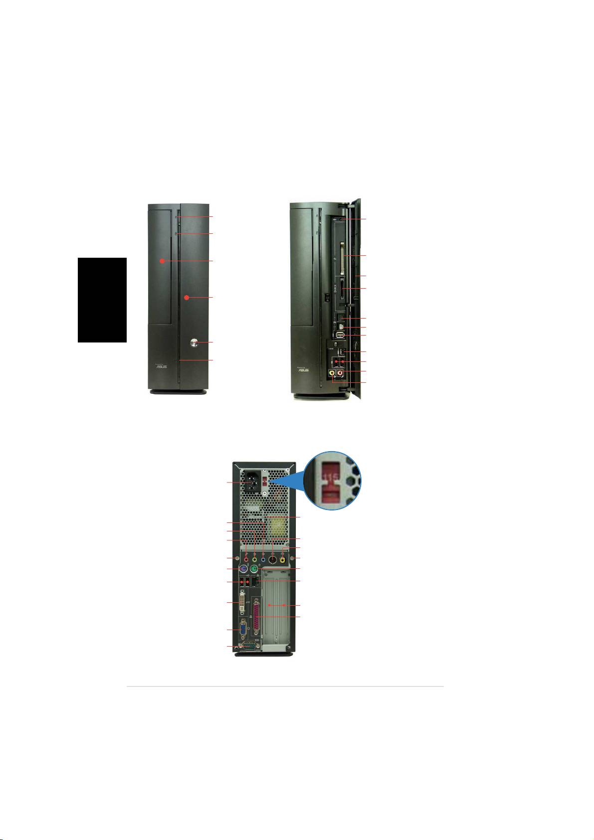
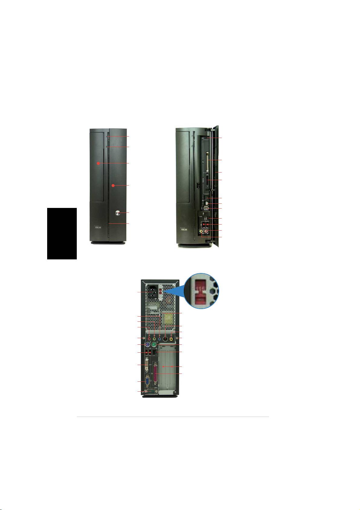
Front panel features
CloseClose
CloseClose
Close
OpenOpen
OpenOpen
Open
English
Optical driveOptical drive
Optical driveOptical drive
Optical drive
Reset buttonReset button
Reset buttonReset button
Reset button
eject buttoneject button
eject buttoneject button
eject button
HDD LEDHDD LED
HDD LEDHDD LED
HDD LED
CompactFlashCompactFlash
CompactFlashCompactFlash
CompactFlash
®
Optical driveOptical drive
Optical driveOptical drive
Optical drive
card slotcard slot
card slotcard slot
card slot
bay coverbay cover
bay coverbay cover
bay cover
Front panel coverFront panel cover
Front panel coverFront panel cover
Front panel cover
3-in-1 card reader3-in-1 card reader
3-in-1 card reader3-in-1 card reader
3-in-1 card reader*
PressPress
PressPress
Press
to open to open
to open to open
to open
the front the front
the front the front
the front
panelpanel
panelpanel
panel
covercover
covercover
cover
S/PDIF In portS/PDIF In port
S/PDIF In portS/PDIF In port
S/PDIF In port
S/PDIF Out portS/PDIF Out port
S/PDIF Out portS/PDIF Out port
S/PDIF Out port
6-pin IEEE 1394 port6-pin IEEE 1394 port
6-pin IEEE 1394 port6-pin IEEE 1394 port
6-pin IEEE 1394 port
Power buttonPower button
Power buttonPower button
Power button
4-pin IEEE 1394 port4-pin IEEE 1394 port
4-pin IEEE 1394 port4-pin IEEE 1394 port
4-pin IEEE 1394 port
Power LEDPower LED
Power LEDPower LED
Power LED
USB 2.0 portsUSB 2.0 ports
USB 2.0 portsUSB 2.0 ports
USB 2.0 ports
Headphone portHeadphone port
Headphone portHeadphone port
Headphone port
Microphone portMicrophone port
Microphone portMicrophone port
Microphone port
* Memory Stick
®
/Pro™, SecureDigital™,
MultiMediaCard
Rear panel features
Power connectorPower connector
Power connectorPower connector
Power connector
Voltage selector*Voltage selector*
Voltage selector*Voltage selector*
Voltage selector*
Power supply air ventsPower supply air vents
Power supply air ventsPower supply air vents
Power supply air vents
Line In portLine In port
Line In portLine In port
Line In port
Line Out portLine Out port
Line Out portLine Out port
Line Out port
Microphone portMicrophone port
Microphone portMicrophone port
Microphone port
S-Video Out portS-Video Out port
S-Video Out portS-Video Out port
S-Video Out port
TV Out portTV Out port
TV Out portTV Out port
TV Out port
Cover screwCover screw
Cover screwCover screw
Cover screw
Cover screwCover screw
Cover screwCover screw
Cover screw
PS/2 keyboard portPS/2 keyboard port
PS/2 keyboard portPS/2 keyboard port
PS/2 keyboard port
PS/2 mouse portPS/2 mouse port
PS/2 mouse portPS/2 mouse port
PS/2 mouse port
USB 2.0 portsUSB 2.0 ports
USB 2.0 portsUSB 2.0 ports
USB 2.0 ports
LAN (RJ-45) portLAN (RJ-45) port
LAN (RJ-45) portLAN (RJ-45) port
LAN (RJ-45) port
DVI Out portDVI Out port
DVI Out portDVI Out port
DVI Out port
PCI slot metal bracketsPCI slot metal brackets
PCI slot metal bracketsPCI slot metal brackets
PCI slot metal brackets
Parallel portParallel port
Parallel portParallel port
Parallel port
VGA portVGA port
VGA portVGA port
VGA port
* The system’s power supply unit has a
Serial portSerial port
Serial portSerial port
Serial port
115 V/230 V voltage selector switch located
near the power connector. Use this switch to
select the correct system input voltage
according to the voltage supply in your area.
22
22
2
Quick installation guideQuick installation guide
Quick installation guideQuick installation guide
Quick installation guide
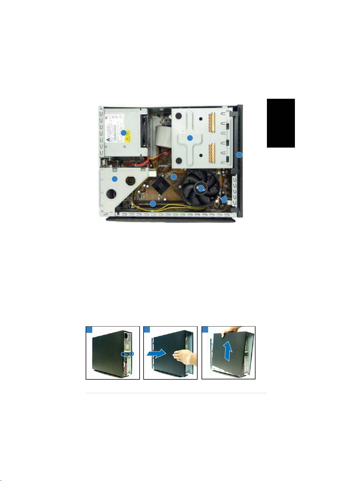
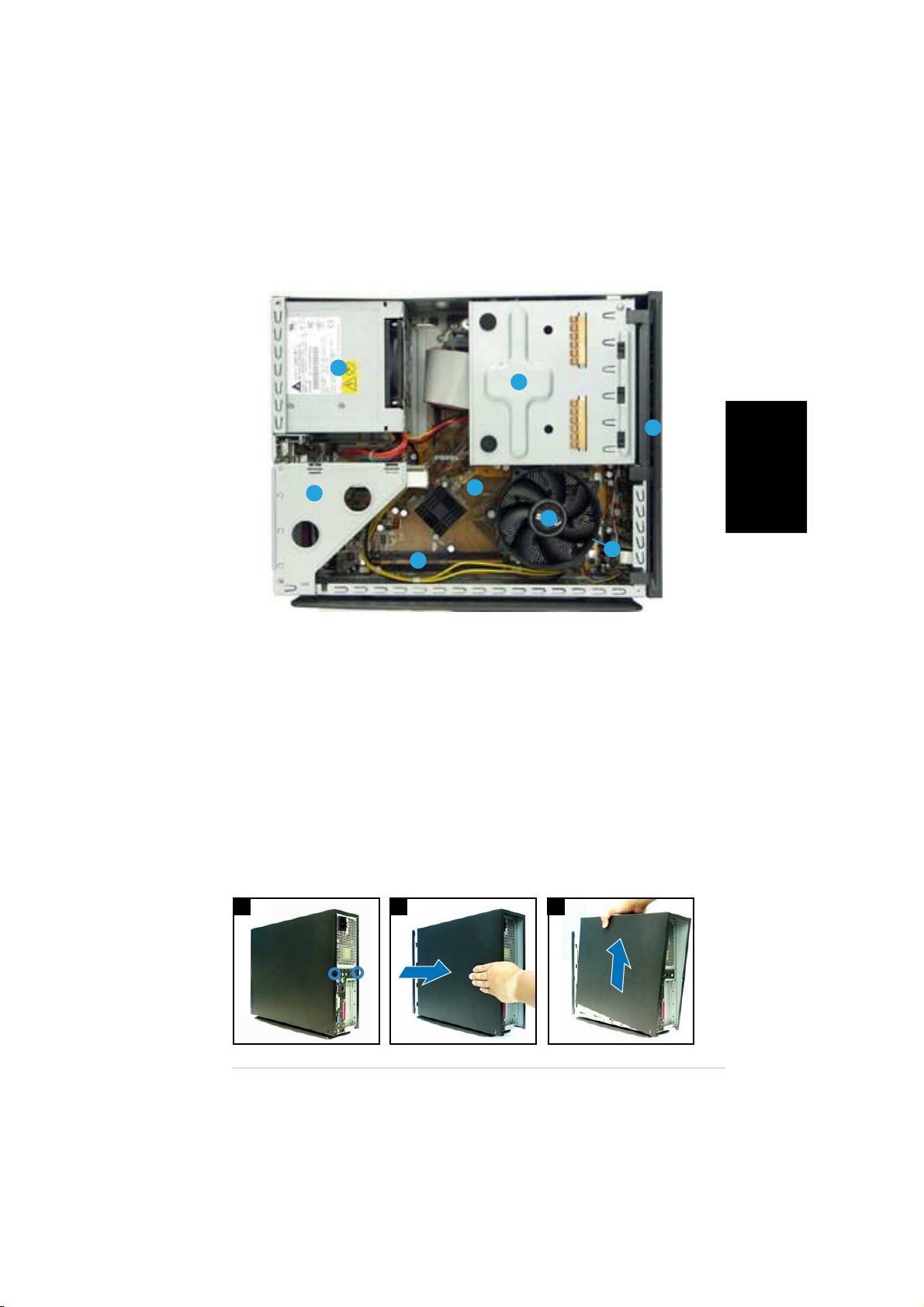
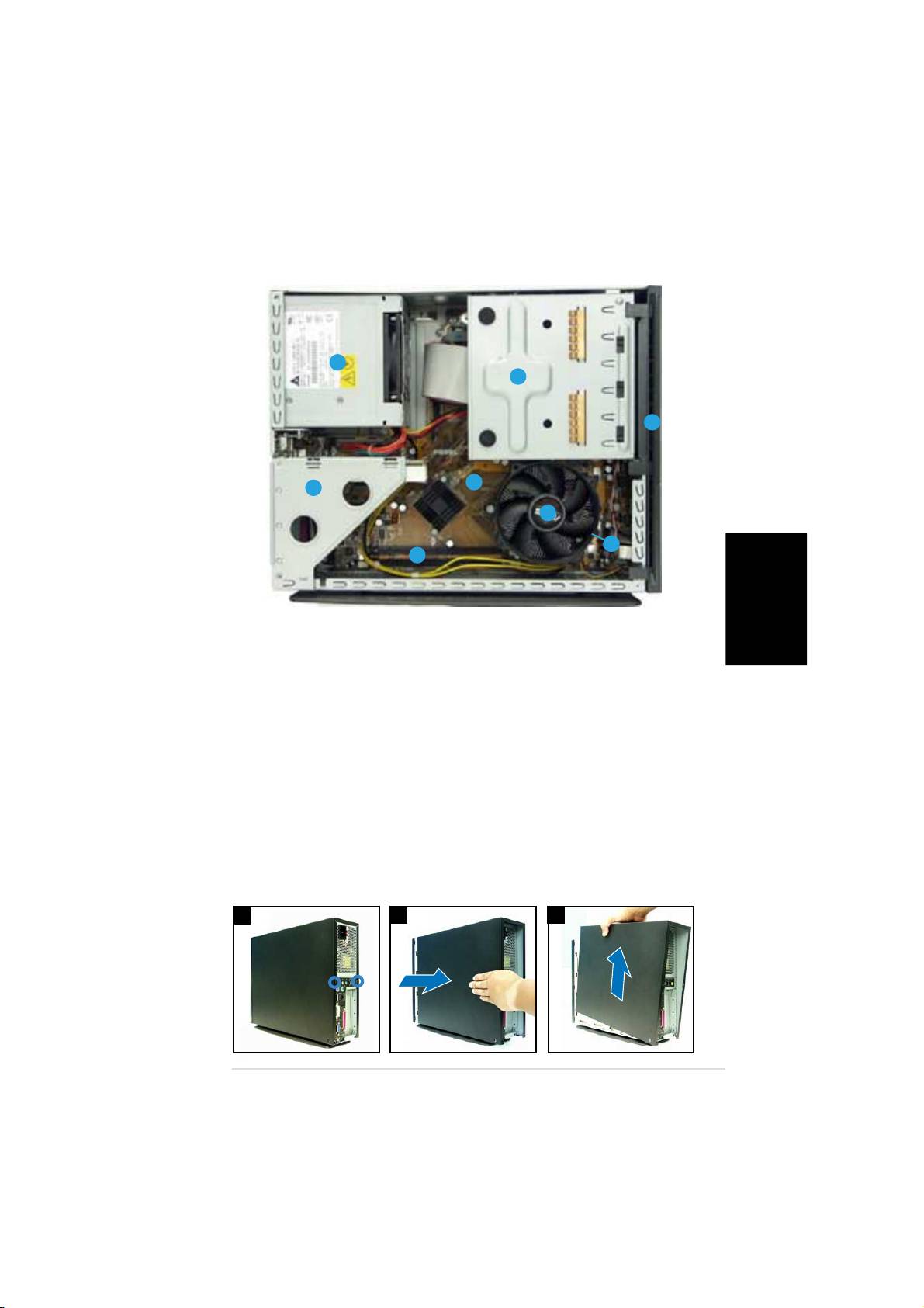
Internal components
English
33
33
3
11
11
1
22
22
2
55
55
5
44
44
4
88
88
8
77
77
7
66
66
6
1. 5.25-inch optical drive and
5. ASUS motherboard
3.5 inch hard disk drive cage
6. DIMM sockets
2. Front panel cover
7. LGA775 socket
(under the CPU
3. Power supply unit
fan and heatsink assembly)
4. PCI card riser bracket
8. CPU fan and heatsink assembly
(connected to the
motherboard PCI slot)
Removing the cover
1. Remove the cover screws. Keep the screws for later use.
2. Pull the cover slightly toward the rear panel.
3. Lift the cover, then set aside.
11
11
1
22
22
2
33
33
3
Quick installation guideQuick installation guide
Quick installation guideQuick installation guide
Quick installation guide
33
33
3
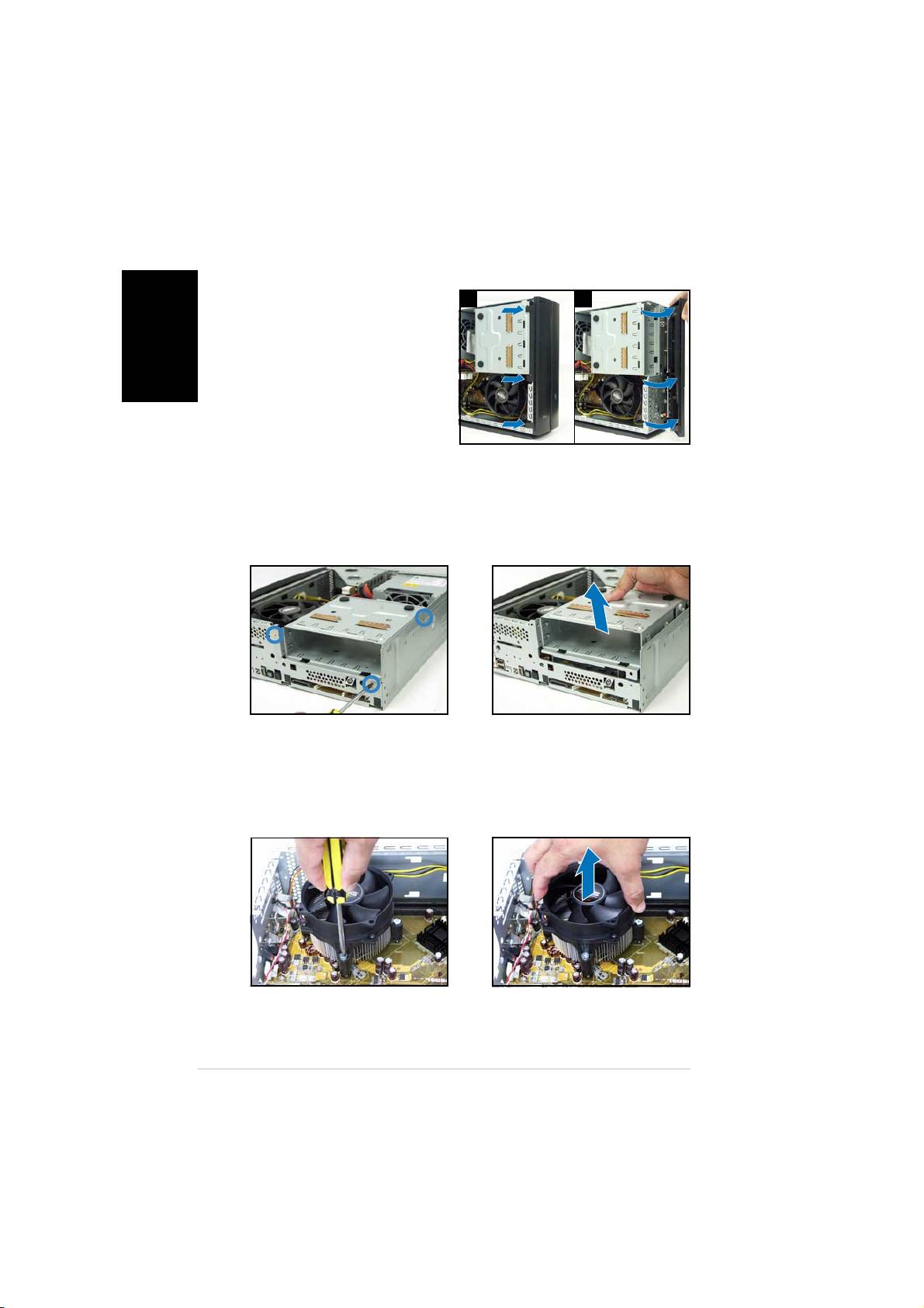
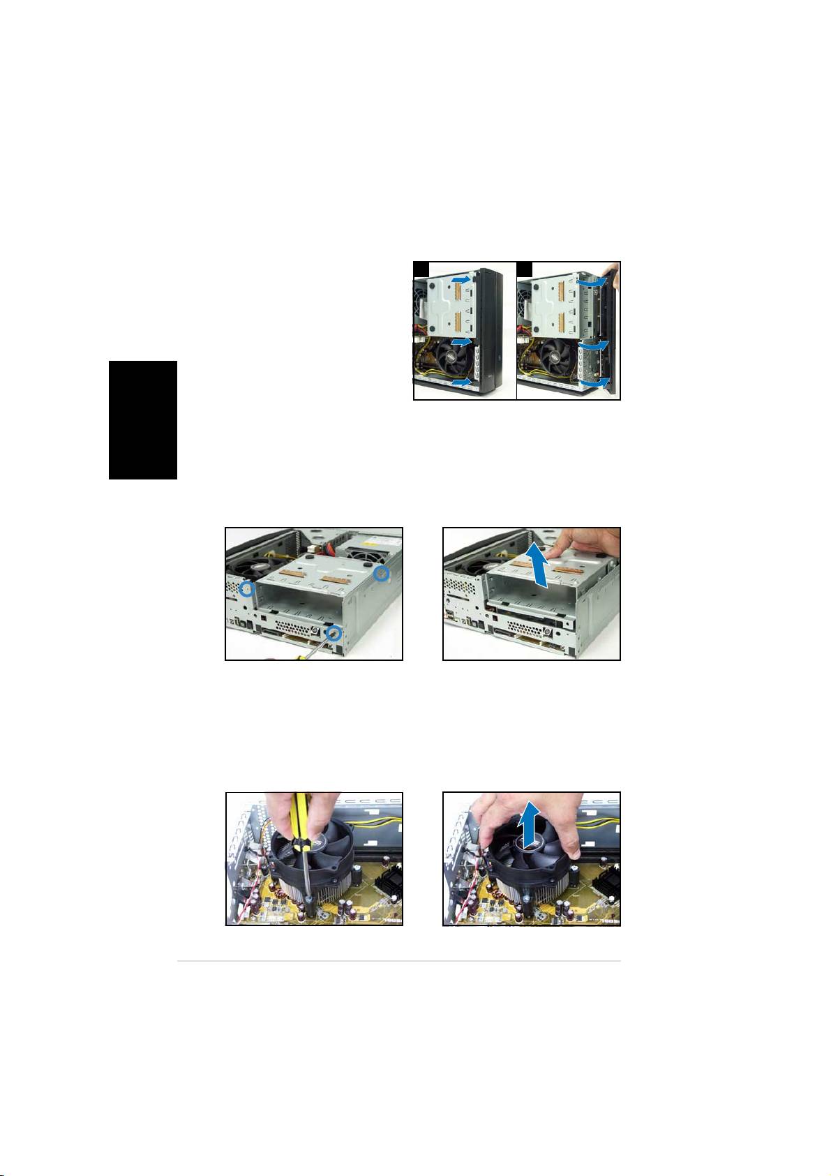
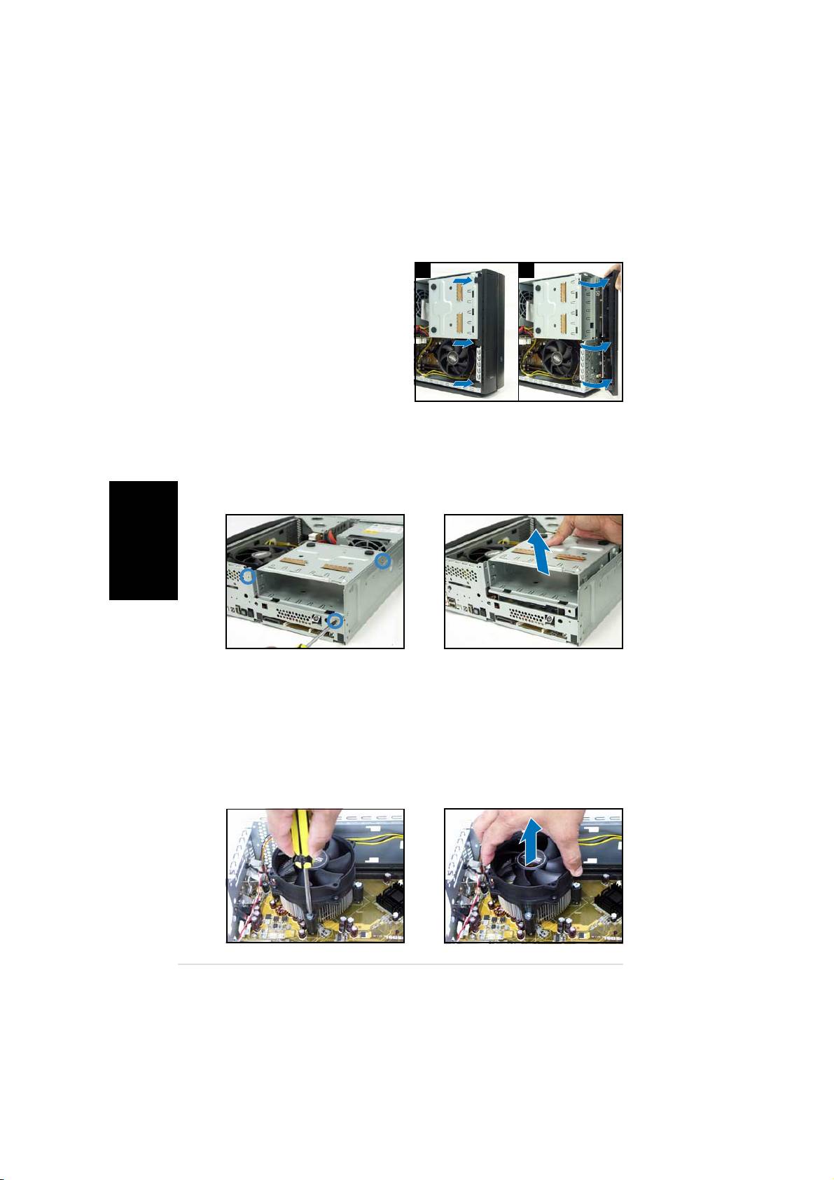
Removing the front panel cover
1. Lift the front panel cover
11
11
1
22
22
2
English
hooks outward.
2. Carefully remove the front
panel cover, then set it aside.
Removing the storage drive assembly
1. Lay the system on its side,
2. Lift the storage drive
then locate and remove three
assembly, then set aside.
storage drive assembly screws.
Removing the CPU fan and heatsink
1. Disconnect the CPU fan cable.
3. Lift the CPU fan and heatsink
assembly, then set aside.
2. Loosen the CPU fan and
heatsink assembly screws.
44
44
4
Quick installation guideQuick installation guide
Quick installation guideQuick installation guide
Quick installation guide
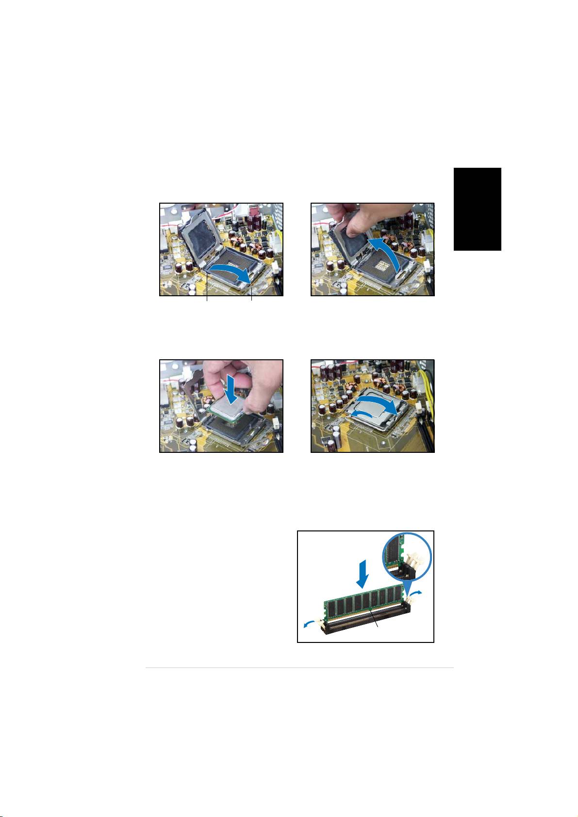
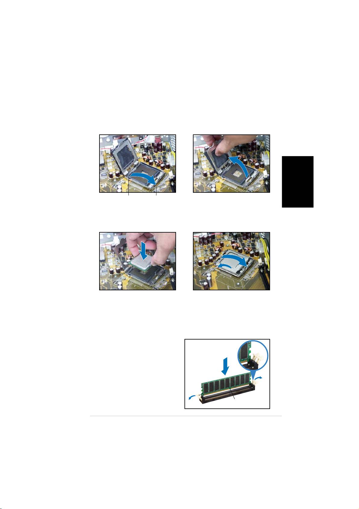
Installing the CPU
1. Unlock the load lever, then lift
2. Lift the load plate, then
to a 90º-100º angle.
remove the PnP cap.
English
Retention tabRetention tab
Retention tabRetention tab
Retention tab
Load leverLoad lever
Load leverLoad lever
Load lever
3. Install the CPU. The CPU fits in
4. Close the load plate, then lock
only one orientation.
the load lever.
5. Reinstall the CPU fan and heatsink assembly, then reconnect the CPU
fan cable to the CPU fan connector on the motherboard. Refer to the
instructions in the previous section for details.
Installing a DIMM
1. Locate the DIMM sockets in the
UnlockedUnlocked
UnlockedUnlocked
Unlocked
motherboard.
retaining clipretaining clip
retaining clipretaining clip
retaining clip
2. Unlock a DIMM socket by
pressing the retaining clips
outward.
3. Align a DIMM on the socket such
that the notch on the DIMM
matches the break on the
socket.
DDR DIMM notchDDR DIMM notch
DDR DIMM notchDDR DIMM notch
DDR DIMM notch
Quick installation guideQuick installation guide
Quick installation guideQuick installation guide
Quick installation guide
55
55
5
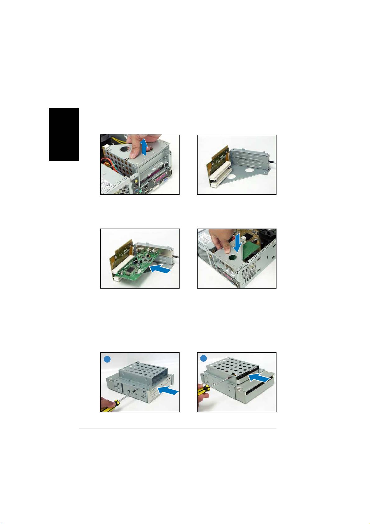
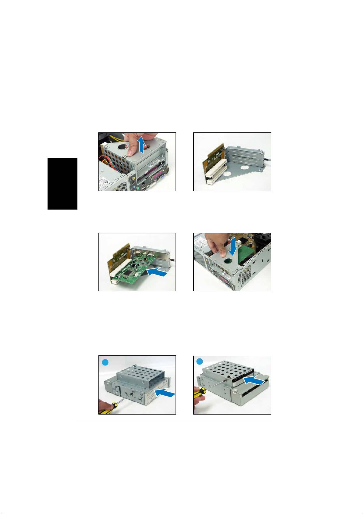
Installing an expansion card
1. Lift the PCI riser card
2. Remove the metal cover
English
assembly to remove.
opposite the slot that you
intend to use.
3. Insert the card connector to
4. Reinstall the PCI riser card
the slot, then press the card
assembly. Make sure that the
firmly until it fits in place.
riser card connector sits properly
Secure the card with a screw.
on the motherboard PCI slot.
Installing optical and storage drives
1. Turn the storage drive assembly upside down with the 3.5-inch bay on
top of the 5.25-inch bay.
2. Insert the optical drive upside down to the 5.25-inch bay, then secure
it with two screws on both sides.
3. Turn the storage drive assembly, insert the hard disk drive upside down to
the 3.5-inch bay, then secure it with two screws on both sides.
22
22
2
3
33
33
66
66
6
Quick installation guideQuick installation guide
Quick installation guideQuick installation guide
Quick installation guide
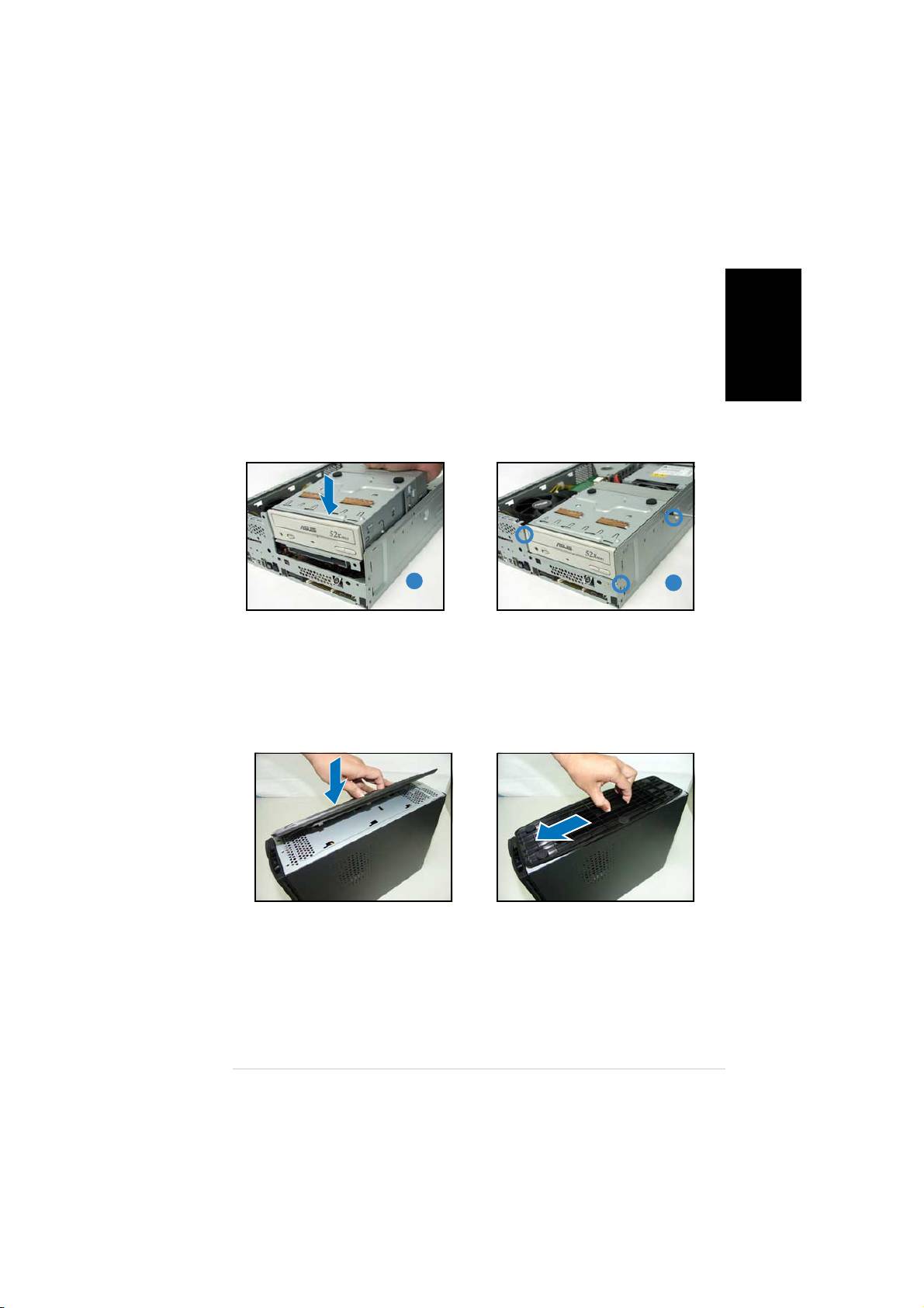
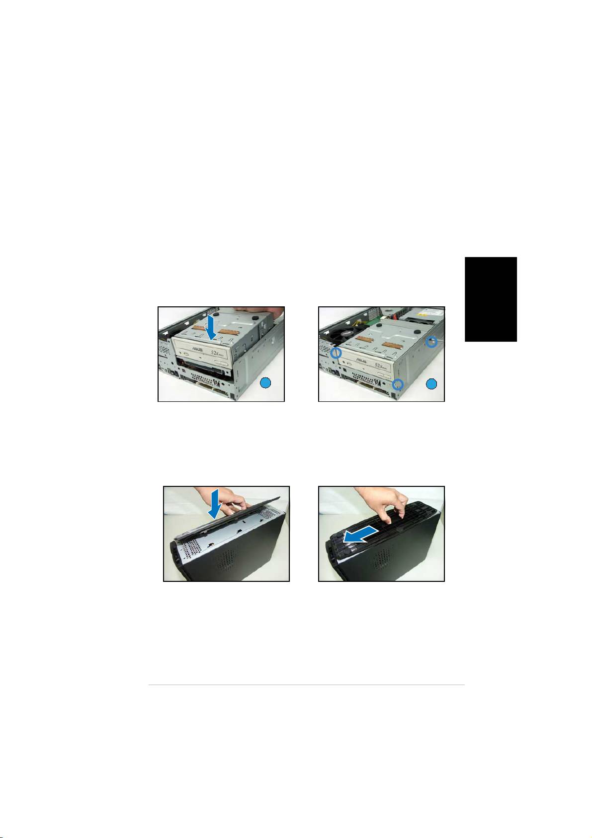
Reinstalling the storage drive assembly
Before reinstalling the storage drive assembly, connect the IDE and power
plugs to the IDE and power connectors at the back of the drives.
1. Connect the black plug of the IDE cable to the optical drive, then the
gray plug to the hard disk drive.
English
2. Connect the 4-pin power plugs to the power connectors at the back
of the drives.
3. Install the storage drive assembly to the chassis.
4. Secure the storage drive assembly with three screws.
33
33
3
44
44
4
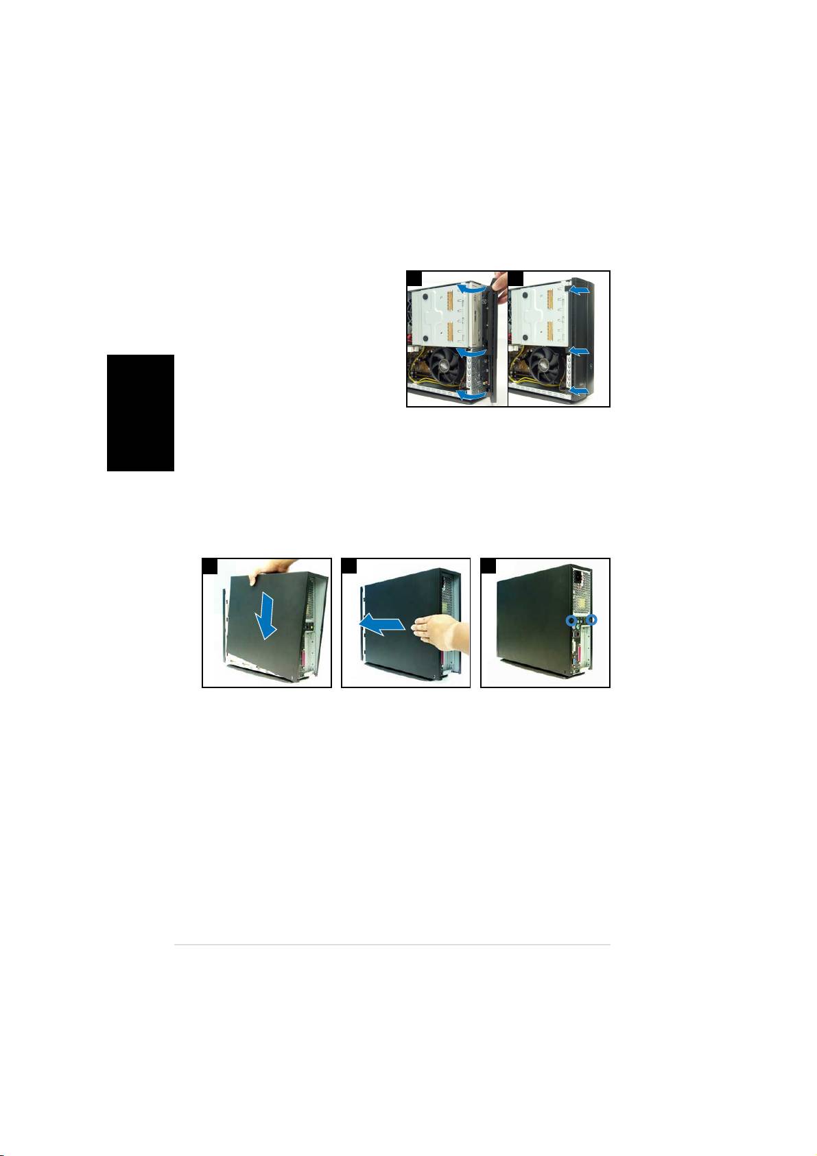
Installing the foot stand
1. Match the foot stand hooks to
2. Pull the foot stand to the
the holes on the chassis.
direction of the arrow until the
lock clicks in place.
To remove the foot stand, lift the lock, then slightly push the foot stand to
the direction of the rear panel until it disengages from the chassis.
Quick installation guideQuick installation guide
Quick installation guideQuick installation guide
Quick installation guide
77
77
7
Reinstalling the front panel cover
English
1. Insert the front panel cover
11
11
1
22
22
2
tabs to the holes at the right
side of the chassis, then close.
2. Insert the front panel cover
hooks to the chassis tabs until
the front panel cover fits in
place.
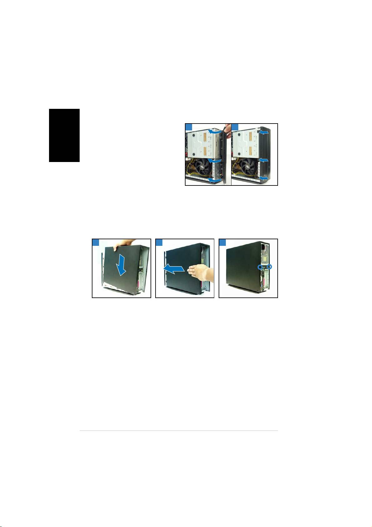
Reinstalling the cover
1. Install the cover to the chassis. Make sure the cover tabs fit the chassis rails.
2. Push the cover toward the front panel until it fits in place.
3. Secure the cover with two screws.
11
11
1
22
22
2
33
33
3
88
88
8
Quick installation guideQuick installation guide
Quick installation guideQuick installation guide
Quick installation guide
Pundit P1-PH1
Système barebone
Français
Guide d’installation rapide
Caractéristiques de la façade
FerméFermé
FerméFermé
Fermé
OuvertOuvert
OuvertOuvert
Ouvert
Bouton d’ejectionBouton d’ejection
Bouton d’ejectionBouton d’ejection
Bouton d’ejection
du lecteur optiquedu lecteur optique
du lecteur optiquedu lecteur optique
du lecteur optique
Bouton ResetBouton Reset
Bouton ResetBouton Reset
Bouton Reset
LED HDDLED HDD
LED HDDLED HDD
LED HDD
Slot pour cartesSlot pour cartes
Slot pour cartesSlot pour cartes
Slot pour cartes
Capot de la baieCapot de la baie
Capot de la baieCapot de la baie
Capot de la baie
CompactFlashCompactFlash
CompactFlashCompactFlash
CompactFlash
®®
®®
®
du lecteur optiquedu lecteur optique
du lecteur optiquedu lecteur optique
du lecteur optique
Français
Capot de la faç adeCapot de la faç ade
Capot de la faç adeCapot de la faç ade
Capot de la faç ade
Appuyez pourAppuyez pour
Appuyez pourAppuyez pour
Appuyez pour
Lecteur de carteLecteur de carte
Lecteur de carteLecteur de carte
Lecteur de carte
ouvrir le capot deouvrir le capot de
ouvrir le capot deouvrir le capot de
ouvrir le capot de
3 en 1*3 en 1*
3 en 1*3 en 1*
3 en 1*
la faç adela faç ade
la faç adela faç ade
la faç ade
Port S/PDIF InPort S/PDIF In
Port S/PDIF InPort S/PDIF In
Port S/PDIF In
Port S/PDIF OutPort S/PDIF Out
Port S/PDIF OutPort S/PDIF Out
Port S/PDIF Out
BoutonBouton
BoutonBouton
Bouton
Port IEEE 1394 6 brochesPort IEEE 1394 6 broches
Port IEEE 1394 6 brochesPort IEEE 1394 6 broches
Port IEEE 1394 6 broches
d ’ alimentationd ’ alimentation
d ’ alimentationd ’ alimentation
d ’ alimentation
Port IEEE 1394 4 brochesPort IEEE 1394 4 broches
Port IEEE 1394 4 brochesPort IEEE 1394 4 broches
Port IEEE 1394 4 broches
LEDLED
LEDLED
LED
Ports USB 2.0Ports USB 2.0
Ports USB 2.0Ports USB 2.0
Ports USB 2.0
d ’ alimentationd ’ alimentation
d ’ alimentationd ’ alimentation
d ’ alimentation
Port CasquePort Casque
Port CasquePort Casque
Port Casque
Port MicrophonePort Microphone
Port MicrophonePort Microphone
Port Microphone
* Memory Stick®/Pro™, SecureDigital™,
MultiMediaCard
Caractéristiques de l’arrière
ConnecteurConnecteur
ConnecteurConnecteur
Connecteur
S é lecteur de tension*S é lecteur de tension*
S é lecteur de tension*S é lecteur de tension*
S é lecteur de tension*
d ’ alimentationd ’ alimentation
d ’ alimentationd ’ alimentation
d ’ alimentation
Trous d’ a ération de l’alimentation
Trous d’ a ération de l’alimentationTrous d’ a ération de l’alimentation
Trous d’ a ération de l’alimentationTrous d’ a ération de l’alimentation
Port Line InPort Line In
Port Line InPort Line In
Port Line In
Port Line OutPort Line Out
Port Line OutPort Line Out
Port Line Out
Port MicrophonePort Microphone
Port MicrophonePort Microphone
Port Microphone
Port S-Video Out
Port S-Video OutPort S-Video Out
Port S-Video OutPort S-Video Out
Port TV Out
Port TV OutPort TV Out
Port TV OutPort TV Out
Vis du capotVis du capot
Vis du capotVis du capot
Vis du capot
Vis du capot
Vis du capotVis du capot
Vis du capotVis du capot
Port clavier PS/2Port clavier PS/2
Port clavier PS/2Port clavier PS/2
Port clavier PS/2
Port souris PS/2
Port souris PS/2Port souris PS/2
Port souris PS/2Port souris PS/2
Ports USB 2.0Ports USB 2.0
Ports USB 2.0Ports USB 2.0
Ports USB 2.0
Port LAN (RJ-45)
Port LAN (RJ-45)Port LAN (RJ-45)
Port LAN (RJ-45)Port LAN (RJ-45)
Port DVI OutPort DVI Out
Port DVI OutPort DVI Out
Port DVI Out
Brackets mé talliques des ports PCI
Brackets mé talliques des ports PCIBrackets mé talliques des ports PCI
Brackets mé talliques des ports PCIBrackets mé talliques des ports PCI
Port parallè le
Port parallè lePort parallè le
Port parallè lePort parallè le
Port VGAPort VGA
Port VGAPort VGA
Port VGA
*L’alimentation du système est équipée d’un
sélecteur de tension 115 V/230 V situé près
Port Sé riePort Sé rie
Port Sé riePort Sé rie
Port Sé rie
du connecteur d’alimentation. Utilisez cet
interrupteur pour choisir la bonne tension
d’entrée en fonction des standards utilisés
dans votre région.
22
22
2
Guide d’installation rapideGuide d’installation rapide
Guide d’installation rapideGuide d’installation rapide
Guide d’installation rapide
Composants internes
33
33
3
11
11
1
22
22
2
55
55
5
44
44
4
Français
88
88
8
77
77
7
66
66
6
1. Bloc du lecteur optique 5.25’’
5. Carte mère ASUS
et du lecteur de disque dur 3.5’’.
6. Sockets DIMM
2. Façade
7. Socket LGA775
(sous le
3. Alimentation
système de refroidissement du
CPU)
4. Bracket du PCI Card Riser
(connecté au slot PCI de la
8. Système de refroidissement du
carte mère)
CPU
Enlever le capot
1. Enlevez les deux vis. Conservez les vis pour un usage ultérieur.
2. Tirez légèrement le panneau vers l’arrière.
3. Soulevez le capot, puis basculez-le.
11
11
1 22
22
2
33
33
3
Guide d’installation rapideGuide d’installation rapide
Guide d’installation rapideGuide d’installation rapide
Guide d’installation rapide
33
33
3
Retirer le capot de la façade
1. Levez les crochets du capot
11
11
1
22
22
2
avant vers l’extérieur.
2. Retirez avec précaution le
capot, puis mettez-le de côté.
Français
Retirer l ’ensemble de stockage
1. Posez le système sur le côté,
2. Soulevez l’ensemble de
puis localisez et retirez les
stockage, puis mettez-le de
trois vis de l’ensemble de
côté.
stockage.
Retirez le dissipateur et le ventilateur du CPU
1. Déconnectez le câble de
3. Soulevez l’ensemble
ventilation du CPU.
dissipateur/ventilateur du CPU,
puis mettez-le de côté.
2. Retirez les vis de l’ensemble
dissipateur/ventilateur du CPU.
44
44
4
Guide d’installation rapideGuide d’installation rapide
Guide d’installation rapideGuide d’installation rapide
Guide d’installation rapide
Installer un CPU
1. Soulevez le levier dans la
2. Soulevez la plaque, puis retirez
direction de la flèche à un
le couvercle PnP.
angle de 90º-100º .
Français
Onglet de ré tentionOnglet de ré tention
Onglet de ré tentionOnglet de ré tention
Onglet de ré tention
LevierLevier
LevierLevier
Levier
3. Installez le CPU. Le CPU ne
4. Refermez la plaque puis
peut être placé que dans un
verrouillez le levier.
seul sens.
5. Réinstallez l’ensemble dissipateur/ventilateur du CPU, puis
reconnectez le câble du ventilateur CPU au connecteur de la carte
mère marqué CPU_FAN. Référez-vous aux instructions de la section
précédente pour plus de détails.
Installer un module DIMM
1. Localisez les sockets DIMM de la
Clip de ré tentionClip de ré tention
Clip de ré tentionClip de ré tention
Clip de ré tention
carte mère.
d é verrouilléd é verrouillé
d é verrouilléd é verrouillé
d é verrouillé
2. Déverrouillez un socket DIMM en
pressant sur les clips de
rétention vers l’extérieur.
3. Alignez un module DIMM sur le
socket de sorte que l’encoche
sur la DIMM corresponde à
l’ergot du socket.
Encoche du DIMMEncoche du DIMM
Encoche du DIMMEncoche du DIMM
Encoche du DIMM
DDRDDR
DDRDDR
DDR
Guide d’installation rapideGuide d’installation rapide
Guide d’installation rapideGuide d’installation rapide
Guide d’installation rapide
55
55
5
Installer une carte d’extension
1. Soulevez l’ensemble PCI Riser
2. Retirez la protection
Card pour le retirez du châssis.
métallique faisant face au slot
que vous désirez utiliser.
Français
3. Insérez le connecteur de la
4. Réinstallez l’ensemble PCI Riser
carte dans le slot et pressez
Card. Assurez-vous que le
jusqu’à ce que la carte soit en
connecteur de la riser card soit
place. Sécurisez la carte avec
bien connecté au slot PCI de la
une vis.
carte mère.
Installer un lecteur optique ou de stockage
1. Placez l’ensemble de stockage de façon à ce que la baie 3.5” soit au
dessus de la baie 5.25”.
2. Insérez le lecteur optique dans la baie 5.25”, puis sécurisez-le avec
deux vis de chaque côté.
3. Insérez le disque dur dans la baie 3.5”, puis sécurisez-le avec deux vis
de chaque côté.
22
22
2
33
33
3
66
66
6
Guide d’installation rapideGuide d’installation rapide
Guide d’installation rapideGuide d’installation rapide
Guide d’installation rapide
Réinstaller l’ensemble de stockage
Avant de réinstaller l’ensemble de stockage, connectez les prises IDE et
d’alimentation aux connecteurs IDE et d’alimentation situés à l’arrière des
lecteurs.
1. Connectez la prise noire du câble IDE au lecteur optique, puis la prise
grise au disque dur.
2. Connectez la prise d’alimentation 4 broches aux connecteurs
d’alimentation situés à l’arrière des lecteurs.
3. Installez l’ensemble de stockage sur le châssis.
4. Sécurisez l’ensemble de stockage avec trois vis.
Français
33
33
3
44
44
4
Installer le pied de support
1. Faites correspondre les
2. Tirez le pied de support dans
crochets du pied de support
la direction de la flèche jusqu’à
aux ouvertures sur le châssis.
ce qu’il soit bien en place.
Pour retirer le pied de support, soulevez le verrou, puis poussez
délicatement le pied de support jusqu’à ce qu’il se désengage du châssis.
Guide d’installation rapideGuide d’installation rapide
Guide d’installation rapideGuide d’installation rapide
Guide d’installation rapide
77
77
7
Réinstaller le capot de la façade
1. Insérez les onglets du capot
11
11
1
22
22
2
dans les ouvertures situées à
droite du châssis, puis
refermez-le.
2. Insérez les crochets du capot
de la façade dans les onglets
du châssis jusqu’à ce que le
Français
capot soit bien en place.
Réinstaller le panneau
1. Installer le panneau sur le châssis en vous assurant que les onglets du
panneau soient bien alignés sur les rails du châssis.
2. Poussez le panneau vers l’avant jusqu’à ce qu’il soit bien en place.
3. Sécurisez le panneau avec deux vis.
11
11
1 22
22
2
33
33
3
88
88
8
Guide d’installation rapideGuide d’installation rapide
Guide d’installation rapideGuide d’installation rapide
Guide d’installation rapide
Pundit P1-PH1
Barebone Systeme
Schnellinstallationsanleitung
Deutsch
Frontseite
geschlossengeschlossen
geschlossengeschlossen
geschlossen
offenoffen
offenoffen
offen
AuswurftasteAuswurftaste
AuswurftasteAuswurftaste
Auswurftaste
des optischendes optischen
des optischendes optischen
des optischen
LaufwerkesLaufwerkes
LaufwerkesLaufwerkes
Laufwerkes
Reset-SchalterReset-Schalter
Reset-SchalterReset-Schalter
Reset-Schalter
HDD-LEDHDD-LED
HDD-LEDHDD-LED
HDD-LED
CompactFlashCompactFlash
CompactFlashCompactFlash
CompactFlash
®®
®®
®
--
--
-
SchubladenabdeckungSchubladenabdeckung
SchubladenabdeckungSchubladenabdeckung
Schubladenabdeckung
KartensteckplatzKartensteckplatz
KartensteckplatzKartensteckplatz
Kartensteckplatz
des optischendes optischen
des optischendes optischen
des optischen
LaufwerkesLaufwerkes
LaufwerkesLaufwerkes
Laufwerkes
FrontabdeckungFrontabdeckung
FrontabdeckungFrontabdeckung
Frontabdeckung
3-in-1 Kartenleser3-in-1 Kartenleser
3-in-1 Kartenleser3-in-1 Kartenleser
3-in-1 Kartenleser*
Zum ö ffnen derZum ö ffnen der
Zum ö ffnen derZum ö ffnen der
Zum ö ffnen der
FrontabdeckungFrontabdeckung
FrontabdeckungFrontabdeckung
Frontabdeckung
bitte hierbitte hier
bitte hierbitte hier
bitte hier
S/PDIF-EingangS/PDIF-Eingang
S/PDIF-EingangS/PDIF-Eingang
S/PDIF-Eingang
drü ckendrü cken
drü ckendrü cken
drü cken
S/PDIF-AusgangS/PDIF-Ausgang
S/PDIF-AusgangS/PDIF-Ausgang
S/PDIF-Ausgang
6-6-
6-6-
6-
PP
PP
P
inin
inin
in
--
--
-
IEEEIEEE
IEEEIEEE
IEEE
--
--
-
13941394
13941394
1394
-P-P
-P-P
-P
ortort
ortort
ort
StromschalterStromschalter
StromschalterStromschalter
Stromschalter
Deutsch
44
44
4
--
--
-
PP
PP
P
inin
inin
in
--
--
-
IEEEIEEE
IEEEIEEE
IEEE
--
--
-
13941394
13941394
1394
-P-P
-P-P
-P
ortort
ortort
ort
Betriebs-LEDBetriebs-LED
Betriebs-LEDBetriebs-LED
Betriebs-LED
USB 2.0-Anschlü sseUSB 2.0-Anschlüsse
USB 2.0-Anschlü sseUSB 2.0-Anschlüsse
USB 2.0-Anschlü sse
Kopfhö reranschlussKopfhö reranschluss
Kopfhö reranschlussKopfhö reranschluss
Kopfhö reranschluss
MikrofonanschlussMikrofonanschluss
MikrofonanschlussMikrofonanschluss
Mikrofonanschluss
* Memory Stick
®
/Pro™, SecureDigital™,
MultiMediaCard
Rückseite
StromanschlussStromanschluss
StromanschlussStromanschluss
Stromanschluss
Spannungsschalter*Spannungsschalter*
Spannungsschalter*Spannungsschalter*
Spannungsschalter*
Netzteillü fter
Netzteillü fterNetzteillü fter
Netzteillü fterNetzteillü fter
Line In-AnschlussLine In-Anschluss
Line In-AnschlussLine In-Anschluss
Line In-Anschluss
Line Out-AnschlussLine Out-Anschluss
Line Out-AnschlussLine Out-Anschluss
Line Out-Anschluss
MikrofonanschlussMikrofonanschluss
MikrofonanschlussMikrofonanschluss
Mikrofonanschluss
S-Video-Ausgang
S-Video-AusgangS-Video-Ausgang
S-Video-AusgangS-Video-Ausgang
TV-Ausgang
TV-AusgangTV-Ausgang
TV-AusgangTV-Ausgang
AbdeckungsschraubeAbdeckungsschraube
AbdeckungsschraubeAbdeckungsschraube
Abdeckungsschraube
Abdeckungsschraube
AbdeckungsschraubeAbdeckungsschraube
AbdeckungsschraubeAbdeckungsschraube
PS/2-TastaturanschlussPS/2-Tastaturanschluss
PS/2-TastaturanschlussPS/2-Tastaturanschluss
PS/2-Tastaturanschluss
PS/2-Mausanschluss
PS/2-MausanschlussPS/2-Mausanschluss
PS/2-MausanschlussPS/2-Mausanschluss
USB 2.0-Anschlü sseUSB 2.0-Anschlüsse
USB 2.0-Anschlü sseUSB 2.0-Anschlüsse
USB 2.0-Anschlü sse
LAN (RJ-45)-Anschluss
LAN (RJ-45)-AnschlussLAN (RJ-45)-Anschluss
LAN (RJ-45)-AnschlussLAN (RJ-45)-Anschluss
DVI-AusgangDVI-Ausgang
DVI-AusgangDVI-Ausgang
DVI-Ausgang
PCI-Steckplatz-Metallblenden
PCI-Steckplatz-MetallblendenPCI-Steckplatz-Metallblenden
PCI-Steckplatz-MetallblendenPCI-Steckplatz-Metallblenden
Paralleler Anschluss
Paralleler AnschlussParalleler Anschluss
Paralleler AnschlussParalleler Anschluss
VGA-AnschlussVGA-Anschluss
VGA-AnschlussVGA-Anschluss
VGA-Anschluss
* Das Netzteil ist mit einem 115V/230V-
Spannungsschalter neben dem
Serieller AnschlussSerieller Anschluss
Serieller AnschlussSerieller Anschluss
Serieller Anschluss
Stromanschluss ausgestattet. Verwenden Sie
diesen Schalter, um die passende
Systemeingangsspannung entsprechend Ihrem
Stromversorgungssystem in Ihrer Region
auszuwählen.
22
22
2
SchnellinstallationsanleitungSchnellinstallationsanleitung
SchnellinstallationsanleitungSchnellinstallationsanleitung
Schnellinstallationsanleitung
Interne Komponenten
3
33
33
1
11
11
22
22
2
55
55
5
4
44
44
88
88
8
77
77
7
6
66
66
1. Halterung für optisches
5. ASUS-Motherboard
Deutsch
Laufwerk 5.25-Zoll und 3.5
6. DIMM-Steckplätze
Zoll Festplattenlaufwerk
7. LGA775-Sockel
(unter der
2. Fronttafelabdeckung
CPU-Lüfter-Kühlkörper-Einheit)
3. Netzteil
8. CPU-Lüfter-Kühlkörper-Einheit
4. Befestigungsklammer für PCI-
Karten
(mit dem PCI-Steckplatz
des Motherboards verbunden)
Entfernen der Abdeckung
1. Entfernen Sie die Abdeckungsschrauben. Die Schrauben für spätere
Wiederverwendung gut aufheben.
2. Ziehen Sie das Gehäuse leicht über die rückseitige Abdeckung.
3. Heben Sie die Abdeckung und legen sie zur Seite.
11
11
1 22
22
2
33
33
3
SchnellinstallationsanleitungSchnellinstallationsanleitung
SchnellinstallationsanleitungSchnellinstallationsanleitung
Schnellinstallationsanleitung
33
33
3
Entfernen der Frontabdeckung
1. Haken Sie die Haken der
11
11
1
22
22
2
Frontabdeckung aus.
2. Vorsichtig die Frontabdeckung
entfernen und beiseite stellen.
Entfernen des Laufwerkseinbaurahmens
1. Legen Sie das System auf die
2. Heben Sie die
Seite und entfernen die drei
Laufwerkshalterung heraus
Schrauben der
und stellen Sie beiseite.
Laufwerkshalterung.
Deutsch
Entfernen des Prozessorlüfters und des
Kühlkörpers
1. Trennen Sie die Verbindung
3. Heben Sie den Prozessorlüfter
des CPU-Lüfterkabels.
und Kühlkörper heraus und
stellen beides beiseite.
2. Lösen Sie die Befestigungs-
schrauben des Prozessor-
lüfters und des Kühlkörpers.
44
44
4
SchnellinstallationsanleitungSchnellinstallationsanleitung
SchnellinstallationsanleitungSchnellinstallationsanleitung
Schnellinstallationsanleitung
