Asus P1-P5945GC: Installing the foot stand Reinstalling the front panel cover Reinstalling the cover
Installing the foot stand Reinstalling the front panel cover Reinstalling the cover: Asus P1-P5945GC
Table of contents
- Front/Rear panel features
- Internal components Removing the cover Removing the front panel cover
- Removing the storage drive assembly Removing an AMD CPU fan and heatsink assembly
- Installing a CPU Installing an Intel Installing an AMD CPU
- Installing a DIMM Installing an expansion card
- Installing optical and storage drives Reinstalling the storage drive assembly
- Installing the foot stand Reinstalling the front panel cover Reinstalling the cover
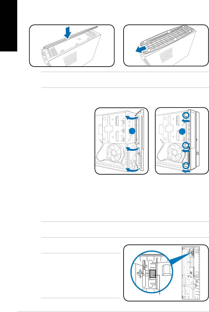
Installing the foot stand
1. Insert the foot stand hooks into
2. Pull the foot stand to the direction
English
the holes on the chassis.
of the arrow until the lock snaps
in place.
NOTE: To remove the foot stand, lift the lock, then slightly push the foot stand to the
direction of the rear panel until it disengages from the chassis.
Reinstalling the front panel cover
Reinstalling the cover
1. Insertthecovertothechasis.Makesurethecovertabstthechasisrails.
2. Pushthecovertowardthefrontpaneluntilittsinplace.
3. Secure the cover with two screws you removed earlier.
NOTE: Refer to the pictures in the section “Removing the cover” on page 3 in reverse
order.
NOTE: For P2 model, if your optical
drive tray fails to eject when you press
the eject button, attach the provided
sticker to the location shown at the back
of the front panel cover. Make sure the
sticker aligns with the optical drive eject
button.
8 Installation manual
R
1. Insert the front panel
cover tabs to the holes
on the right side of the
chassis, then swing
1
2
the front panel cover to
the left.
2. Insert the front panel
cover hooks to the
chassis until the front
panelcovertsin
place.
Sticker


