Indesit DP2GSIX: Instructions for the installer
Instructions for the installer: Indesit DP2GSIX
12
GB
ISO 7/1
ISO 228/1 (FR)
Fig. 3
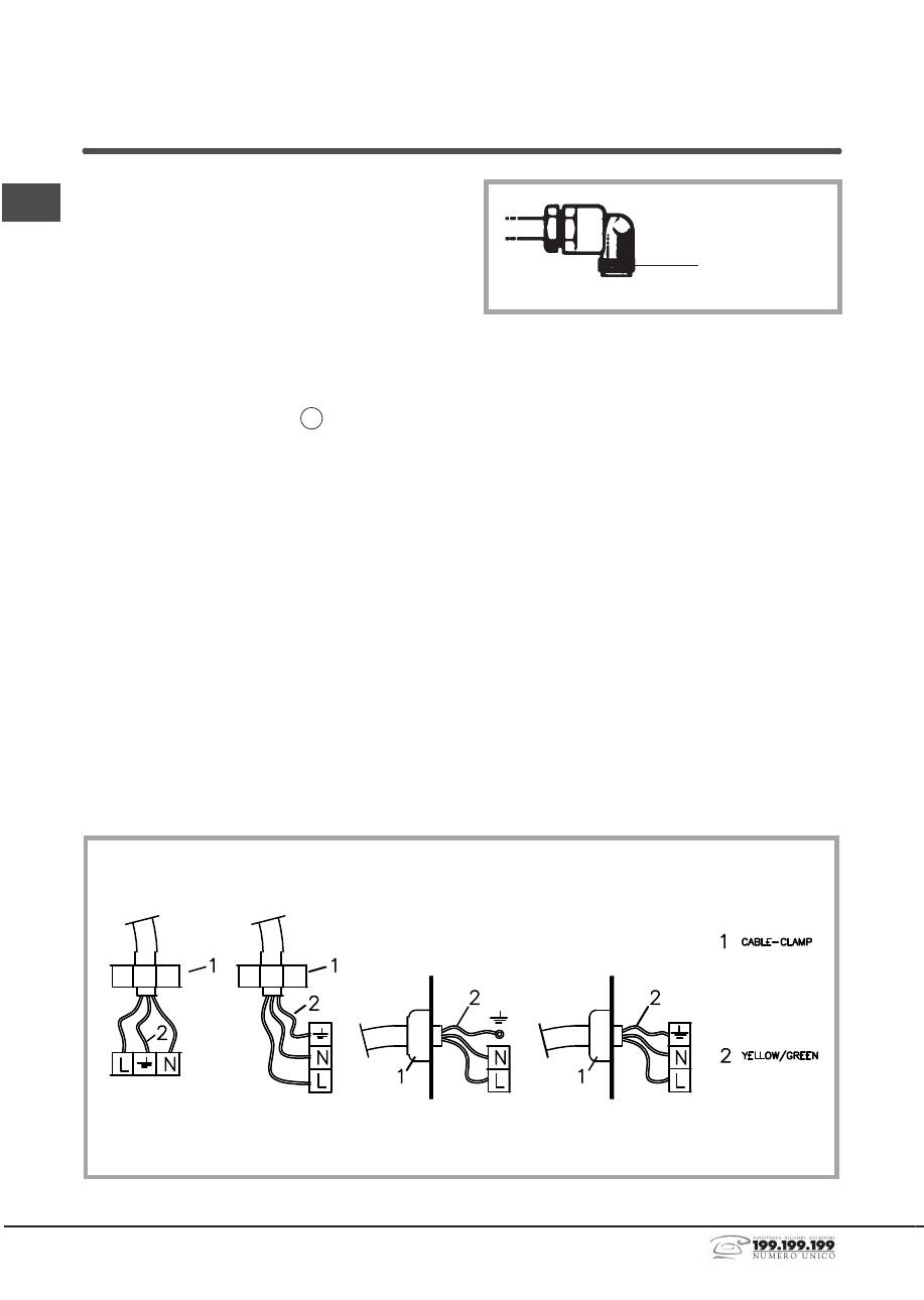
Electrical connection (Fig. 4)
Prior to carrying out the electrical connection, please
ensure that:
• the plant characteristics are such as to follow what is
indicated on the matrix plate placed at the bottom of
the working area;
• that the plant is fitted with an efficient earth connection,
following the standards and law provisions in force.
The earth connection is compulsory in terms of the
law.
Should there be no cable and/or plug on the
equipment, use suitable absorption material for the
working temperature as well, as indicated on the matrix
plate. Under no circumstance must the cable reach a
temperature above 50°C of the ambient tempera-ture.
If connecting directly to the mains power supply,
fit a multi-pole switch of a suitable size for the rated
capacity with a clearance distance which completely
disconnects the power line under overvoltage category
III conditions, consistently with the rules of installation
(the yellow/green earth wir must not be interrupted).
The plug or omnipolar switch must be easily reached
on the installed equipment.
Installation
This appliance is not provided with a combu-stion
product discharge. It is recommended that it be
installed in sufficiently aerated places, in terms of the
laws in force. The quantity of air which is necessary for
combu-stion must not be below 2.0 m
3
/h for each kW of
installed power. See table of burner power.
Positioning (Fig. 2)
The appliance can be fitted into a working area
as illustrated on the corresponding figure. Before
positioning the hob, fit the seal X around the entire
periphery of the hole cut in the worktop.
Gas connection (Fig. 3)
Connect the appliance to the gas cylinder or to the
installation according to the prescribed standards
in force, and ensure beforehand, that the appliance
matches the type of gas available. The type of gas
for which the appliance is predisposed is shown on
the appliance identification plate. Otherwise, see
“Adaptation to various types of gas”. Furthermore,
check that the feed pressure falls within the values
described on the table: “User chacteristics”.
Rigid/semi rigid metal connection Carry out the
connection with fittings and metal pipes (even flexible
pipes) so as to obtain counter stress the inner parts of
the appliance.
N.B.
- when the installation has been carried out, check
the perfect sealing of the entire connection system, by
using a soapy solution.
Fig. 4
Instructions for the installer
13
GB
To avoid all risk, if the power cable becomes damaged,
it must only be replaced by the manufacturer,
by an authorised service centre, or by a qualified
electrician.
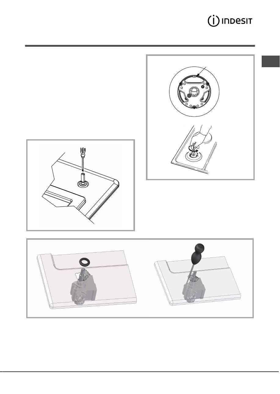
Adaptation to various types of gas (Fig. 5)
Should the appliance be pre-set for a different type of
gas than that available, proceed as follows:
• replace the injectors (Fig. 5) with the corresponding
type of gas to be used (see table “Uses
characteristics”).
• to adjust to the minimum, use a screwdriver on the
screw placed on the tap (Fig. 6) after turning the tap
to its minimum position. For LPG (butane/propane)
screw tight
Fig. 6
wok C3 only
Fig. 5
Fig. 6
Оглавление
- Piano di Cottura
- Istruzioni per l’utente
- Istruzioni per l’installatore
- Assistenza
- Cooking Hob
- Instructions for use
- Instructions for the installer
- Assistance
- Tables de Cuisson
- Notice d’emploi
- Modalités d’installation
- Assistance
- Einbaukochgerät
- Anweisungen für den Benutzer
- Anleitungen für den Installateur
- Kundendienst
- Placa de Cocción
- Instrucciones para el usuario
- Instrucciones para el instalador
- Asistencia
- Mesas de Encastrar
- Instruções para o utilizador
- Instruções para o instalador
- Assistência
- ΐЏϛήϤϠϟ ΕΎϤϴϠόΗ
- ϡΪΨΘγϹ ΕΎϤϴϠόΗ
- ΥΎПΒτϟ
- setüstü ocak
- Kullanım talimatları
- Kurulum yapacak kisi için talimatlar
- teknİk destek
- Варочная поверхность
- Инструкции для пользователя
- Инструкции для технического персонала
- Помощь
- Notes
