Asus P2-PH1: Front/Rear panel features
Front/Rear panel features: Asus P2-PH1
Table of contents
- Front/Rear panel features
- Internal components Removing the cover Removing the front panel cover
- Removing the storage drive assembly Removing the CPU fan and heatsink assembly
- Installing a CPU
- Installing a DIMM Installing an expansion card
- Reinstalling the storage drive assembly
- Installing the foot stand Reinstalling the front panel cover Reinstalling the cover
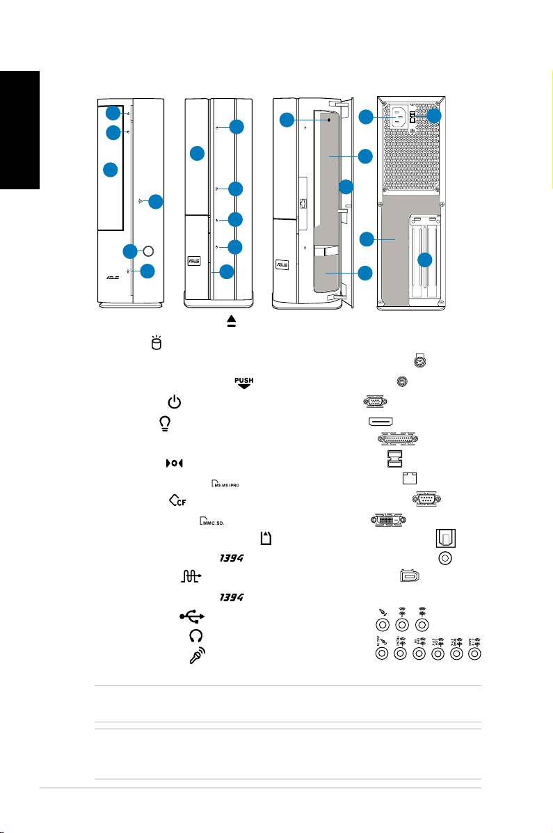
Front/Rear panel features
P1 Front (Close)
P2 Front (Close)
Front (Open)
Rear
English
1
11
12
8
2
2
3
9
3
4
7
4
1
13
5
5
14
6
6
10
1. Optical drive eject button ( )
11. Power connector
12.** Voltage selector switch
2. HDD LED (
)
3. Optical drive bay cover
13.* • PS/2 keyboard port (
)
4. Open the front panel cover (
)
• PS/2 mouse port (
)
• VGA port (
)
5. Power button ( )
• HDMI port (
)
6. Power LED (
)
• Parallel port (
)
7. Front panel cover
8. Reset button (
)
• USB 2.0 ports (
)
9.* • MS/MS Pro card slot (
)
• LAN (RJ-45) port (
)
• CF card slot (
)
• Serial (COM1) port (
)
• SD/MMC card slot (
)
• DVI-D port (
)
• MS/MS Pro/SD/MMC card slot (
)
• Optical S/PDIF Out port (
)
• 6-pin IEEE 1394a port (
)
• Coaxial S/PDIF Out port (
)
• S/PDIF In port (
)
• IEEE 1394a port (
)
10.* • 4-pin IEEE 1394a port (
)
•Audioportscongurations:
• USB 2.0 ports (
)
• 6-channel
• Headphone port (
)
• 8-channel
• Microphone port (
)
14. Expansion slot metal brackets
NOTE: *The front/rear panel slots/ports and their locations may vary, depending on the
model of your system. For detailed descriptions, refer to the system User Guide.
NOTE: **The system’s power supply unit has a 115V / 230V voltage selector switch
located beside the power connector. Use this switch to select the appropriate system
input voltage according to the voltage supply in your area.
2 Installation manual
