Kenwood KRC-694: Connecting Wires to Terminals
Connecting Wires to Terminals: Kenwood KRC-694
KRC-694(E)_U.S_r3 02.11.11 7:34 PM Page 27
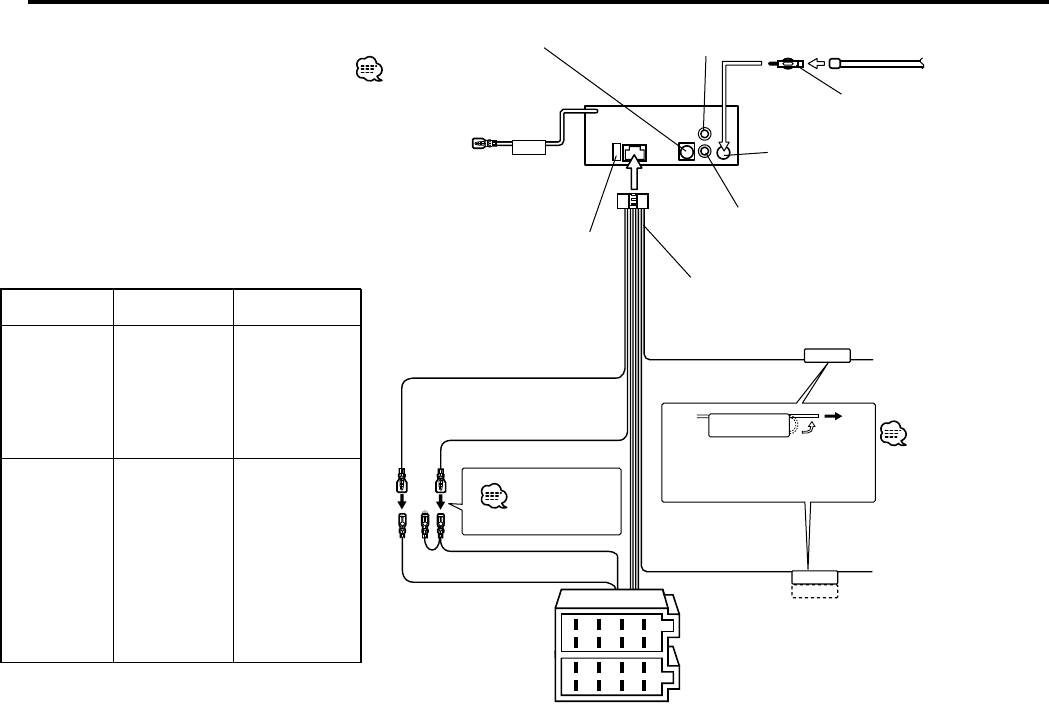
Connecting Wires to Terminals
10
KENWOOD disc changer input 14
Rear left
output (White)
Antenna Cord (ISO) 1
To connect the Disc
changer, consult your
Disc changer manual. 15
Antenna Conversion Adaptor
(ISO–JASO) (Accessory3) 2
To Steering remote
REMO.CONT
(Optional accessory)
FM/AM antenna
input 3
Rear right
output (Red)
Fuse (10A) 13
4
Connector Function Guide
Wiring harness
Pin Numbers for
(Accessory1) 16
Cable Color Functions
ISO Connectors
17
External Power
TEL mute wire (Brown)
Connector
TEL MUTE
Connect to the terminal
Battery wire (Yellow) 6A
that is grounded when
A–4
Yellow
Battery
either the telephone rings
A–5
Blue/White
Power Control
or during conversation. 21
A–7
Red
Ignition (ACC)
To connect the
Black
Earth (Ground)
Ignition wire (Red) 7A
A–8
KENWOOD navigation
Connection
If no connections are made,
system, consult your
do not let the wire come out
navigation manual. 22
Speaker
from the tab. 18a
Connector
See page 280
B–1
Purple
Rear Right (+)
B–2
Purple/Black
Rear Right (–)
Power control/ Motor
B–3
Gray
Front Right (+)
antenna control wire
A–7 Pin (Red) 8
(Blue/White) 20
B–4
Gray/Black
Front Right (–)
P.CONT
Connect either to the
B–5
White
Front Left (+)
ANT.CONT
power control terminal
A–4 Pin (Yellow) 9
when using the optional
B–6
White/Black
Front Left (–)
power amplifier, or to the
8
6
4
2
B–7
Green
Rear Left (+)
antenna control terminal in
Connector A
7
5
3
1
the vehicle. 23
B–8
Green/Black
Rear Left (–)
8
6
4
2
Connector B
7
5
3
1
— 27 —
KRC-694(E)_U.S_r3 02.11.11 7:34 PM Page 28
Connecting Wires to Terminals
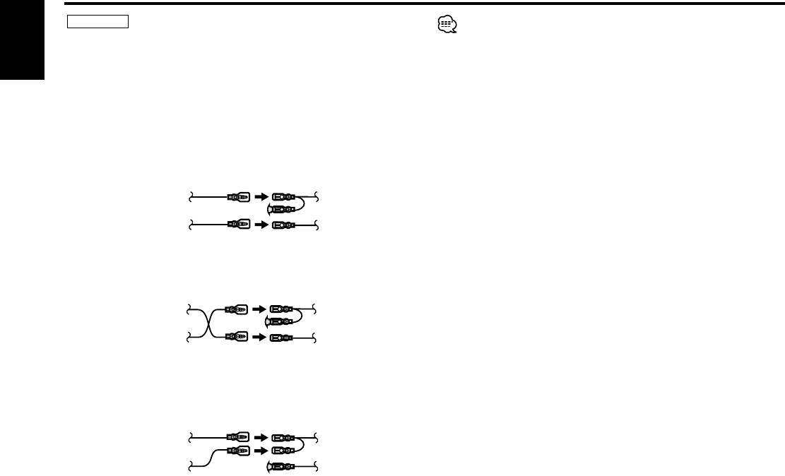
2WARNING
When the connection is made as in 3 above, the unit's power will not
Connecting the ISO Connector
be linked to the ignition key. For that reason, always make sure to turn
The pin arrangement for the ISO connectors depends on the type of
vehicle you drive. Make sure to make the proper connections to
off the unit's power when the ignition is turned off.
To link the unit's power to the ignition, connect the ignition cable
English
prevent damage to the unit.
The default connection for the wiring harness is described in 1 below.
(ACC...red) to a power source that can be turned on and off with the
If the ISO connector pins are set as described in 2 or 3, make the
ignition key.
connection as illustrated.
Please be sure to reconnect the cable as shown 2 below to install
this unit to the Volkswagen vehicles etc.
1 (Default setting) The A-7 pin (red) of the vehicle's ISO connector
is linked with the ignition, and the A-4 pin (yellow) is connected to
the constant power supply.
Unit Vehicle
Ignition cable (Red)
A–7 Pin (Red)
Battery cable (Yellow)
A–4 Pin (Yellow)
2 The A-7 pin (red) of the vehicle's ISO connector is connected to
the constant power supply, and the A-4 pin (yellow) is linked to
the ignition.
Unit Vehicle
Ignition cable (Red)
A–7 Pin (Red)
Battery cable (Yellow)
A–4 Pin (Yellow)
3 The A-4 pin (yellow) of the vehicle's ISO connector is not
connected to anything, while the A-7 pin (red) is connected to the
constant power supply (or both the A-7 (red) and A-4 (yellow) pins
are connected to the constant power supply).
Unit Vehicle
Ignition cable (Red)
A–7 Pin (Red)
Battery cable (Yellow)
A–4 Pin (Yellow)
— 28 —— 28 —
Оглавление
- CASSETTE RECEIVER
- Contents
- Safety precautions
- Safety precautions About Cassette tape
- General features
- General features
- Tuner features
- RDS features
- RDS features
- RDS features Cassette player features
- Cassette player features
- External disc control features
- Menu system
- Menu system
- Menu system
- Accessories
- Connecting Wires to Terminals
- Installation
- Installation
- Troubleshooting Guide
- Troubleshooting Guide
- Specifications
- Cодержание
- Меры предосторожности
- Меры предосторожности О кассетах
- Общие характеристики
- Общие характеристики
- Cвойства тюнера
- Cвойства RDS
- Cвойства RDS
- Cвойства RDS Cвойства кассетного проигрывателя
- Cвойства кассетного проигрывателя
- Функции управления внешним диском
- Система меню
- Система меню
- Система меню
- Принадлежности
- Подсоединение кабелей к гнездам для подключения
- Установка
- Установка
- Поиск и устранение неисправностей
- Поиск и устранение неисправностей
- Технические характеристики
- Treść
- Środki ostrożności
- Środki ostrożności Uwagi dotyczące kaset
- Ogólne możliwości
- Ogólne możliwości
- Możliwości tunera
- Możliwości RDS
- Możliwości RDS
- Możliwości RDS Możliwości odtwarzacza kaset
- Możliwości odtwarzacza kaset
- Możliwości sterowania zewnętrznymi płytami
- Menu systemu
- Menu systemu
- Menu systemu
- Akcesoria
- Podłączanie przewodów do końcówek
- Podłączanie przewodów do końcówek
- Instalacja
- Instalacja
- Przewodnik wykrywania i usuwania usterek
- Przewodnik wykrywania i usuwania usterek
- Dane techniczne


