Indesit K6G20 W: Installation
Installation: Indesit K6G20 W
Installation
The following instructions should be read by a qualified
c) Intensive and prolonged use of the appliance may re-
technician to ensure that the appliance is installed, regu-
sult in the need for supplemental air circulation, e.g.
lated and serviced correctly in compliance with current
opening windows or increasing mechanical venting (if
standards.
present).
Important: Remember to unplug the appliance from
d) Liquified petroleum gas is heavier than the air and,
the mains before making adjustments or doing main-
therefore, settles downwards. Thus, rooms containing
tenance.
LPG cylinders must also be equipped with apertures
to the outside for ventilation of gas in the case of leaks.
Positioning
LPG cylinders must not, therefore, be installed or stored
Important: This unit may be installed and used only in
in rooms or storage areas that are below ground level
permanently ventilated rooms in compliance with current
(cellars, etc.) whether they are partially or completely
National Regulations. The following requirements must
full. It is a good idea to keep only the cylinder being
be observed:
used in the room, positioned so that it is not subject to
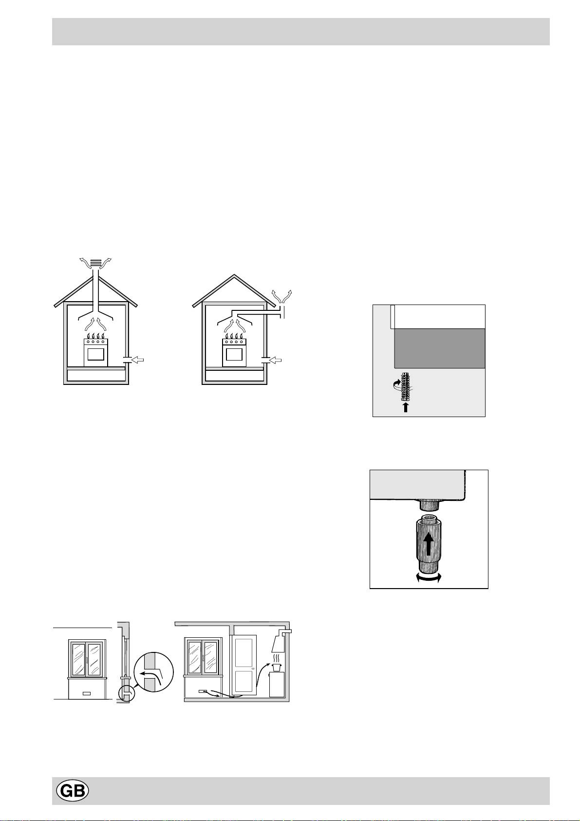
a) The room must be equipped with an exhaust system
heat produced by external sources (ovens, fireplaces,
that vents the combustion fumes to the outside. It may
stoves, etc. ) which are able to increase the tempera-
consist of a hood or an electric fan that automatically
ture of the cylinder above 50°C.
starts each time the appliance is turned on.
Levelling Your Appliance (only on certain models)
4 support feet which are adjusted using screws are located
in the lower part of the cooker. These level off the oven
when necessary. It is essential that the cooker be standing
level.
Flue or Branched Flue System Directly to the Outside
(only for cooking appliances)
b) The room must also have a system to permit proper
air circulation, needed for combustion to occur nor-
Mounting the legs (only on certain models)
mally. The flow of air needed for combustion must not
Press-fit legs are supplied which fit under the base of your
3
be less than 2 m
/h per kW of installed power. The air
cooker.
circulation system may take air directly from the out-
side by means of a pipe with an inner cross section of
2
at least 100 cm
; the opening must not be able to be
accidentally blocked. For those appliances not
equipped with a safety device for accidental flame loss,
the ventilation apertures must be increased by 100%,
2
with the minimum being 200 cm
(Fig. A). The system
can also provide the air needed for combustion by in-
direct means, i.e. from adjacent rooms fitted with air
circulation tubes as described above. However, these
rooms must not be common rooms or bedrooms.
(Fig. B)
.
Detail A Adjacent Room to
Room be Ventilated
Installing the Cooker
The appliance can be installed next to cabinets, provided
they are not taller than the hob. If the cooker is placed in
contact with walls or the sides of adjacent cabinets, they
must be capable of withstanding a rise in temperature of
50°C above room temperature. For proper installation of
the cooker, the following precautions must be taken:
A
a) Kitchen cabinets installed next to the cooker that are
higher than the top of the hob, must be at least 600
Examples of Ventilation Openings Increased Opening Between
mm from the edge of the hob itself.
Comburent Air Door and Floor
b) Hoods must be installed according to the requirements
Fig. A Fig. B
in the installation manual for the hood and, in any case,
at a minimum height of 650 mm.
14
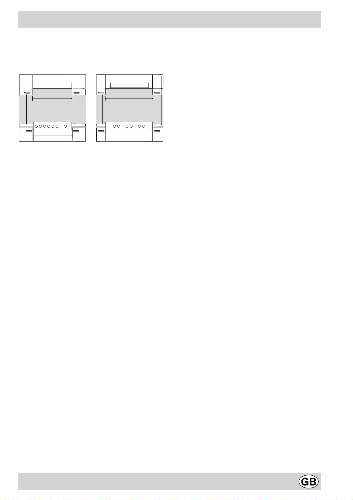
c) If the hood is installed below a wall cabinet, the latter
Connecting a Flexible, Jointless, Stainless Steel
must be at least 700 mm (millimetres) above the sur-
Pipe to a Threaded Attachment
face of the hob. Cabinets installed adjacent to the hood
Remove the hose holder fitted on the appliance. The gas
must be at least 420 mm above the hob, as shown in
supply pipe fitting is a threaded 1/2 gas cylindrical male
Figures C and D.
attachment. Use only pipes and seals that comply with
current National Regulations. The full length of the pipe
when installed must not exceed 2000 mm. After the con-
HOOD
HOOD
nection has been made, make sure that the flexible metal
Min. mm.
600
Min. mm.
900
pipe does not come into contact with moveable parts and
that it is not crushed.
mm.
mm.
420
420
mm. with hood
420
mm. with hood
mm. without hood
420
mm. without hood
Checking the Seal
650
700
650
700
Min.
Min. mm.
Min.
min.
Min. mm.
min.
min.
min.
Important: Once the installation has been completed,
check to make sure that the seals on all the connections
are tight, using a soapy solution (never a flame).
Connecting the Power Supply Cord to the Mains
Fig. C Fig. D
Install a normalised plug corresponding to the load indi-
Making the Gas Connection
cated on the data plate. When connecting the cable di-
T
he appliance should be connected to the mains or to a
rectly to the mains, install an omnipolar circuit-breaker with
gas cylinder in compliance with current directives. Before
a minimum contact opening of 3 mm between the appli-
making the connection, check that the cooker is regulated
ance and the mains. The omnipolar circuit breaker should
for the gas supply you are using. If not, follow the instruc-
be sized according to the load and should comply with
tions indicated in the paragraph “Converting to Different
current regulations (the earth wire should not be inter-
Types of Gas." On some models the gas supply can be
rupted by the circuit breaker). The supply cable should be
connected on the left or on the right, as necessary; to
positioned so that it does not reach a temperature of more
change the connection, reverse the position of the hose
than 50°C with respect to the room temperature, along its
holder with that of the cap and replace the gasket (sup-
length. Before making the connection, check that:
plied with the appliance). When using liquid gas from a
• The limiter valve and the home system can support
cylinder, install a pressure regulator which complies with
the appliance load (see data plate);
the National Regulations.
• The mains are properly earthed in compliance with cur-
Important: Check that the supply pressure complies with
rent safety standards and regulations;
the values indicated in table 1 “Burner and Nozzle Char-
• There is easy access to the socket and omnipolar cir-
acteristics” since this will ensure safe operation, correct
cuit breaker, once the hob has been installed.
consumption and ensure a longer life for your appliance.
N.B.: Never use reducers, adaptors or shunts since they
can cause heating or burning.
Connection with a Hose
Make the connection using a gas hose that complies with
Converting the Cooker to Different Types of Gas
requirements set forth by the current standards. The in-
In order to convert the cooker for use with a type of gas
ner diameters of the pipe are as follows:
different than the one for which it was factory set (indi-
- 8 mm for liquid gas;
cated on the label attached to the lid), the following steps
- 13 mm for methane.
must be taken:
When installing the hose, remember to take the following
a) Replace the hose holder mounted on the appliance
precautions:
with that supplied in the bag of “cooker accessories.”
• No part of the hose must come into contact with parts
Important: The hose holder for liquid gas is marked 8,
whose temperature exceeds 50°C;
the hose holder for methane. In any case, always use a
• The length of the hose should be less than 1500 mm;
new sealing gasket.
• The hose should not be subject to twisting or pulling,
b) Replace the burner nozzles on the hob:
and should not have bends or kinks;
• Remove the grids and slide the burners from their
• The hose should not touch objects with sharp edges,
housings;
corners or moving parts, and it should not be crushed;
• Unscrew the nozzles using a 7 mm socket spanner,
• The full length of the hose should be easy to inspect in
and replace them with nozzles for the new type of gas
order to check its condition.
(see table 1 “Burner and Nozzle Characteristics”).
Check that the hose fits firmly into place at the two ends
• Replace all the components by repeating the steps in
and fix it with clamps complying with current standards. If
reverse order.
any of the above recommendations can not be followed,
flexible metal pipes should be used. If the cooker is in-
stalled in compliance with the requirements for class 2,
subclass 1, it is highly recommended that the gas con-
nection be made with a flexible metal pipe in compliance
with current safety standards.
15
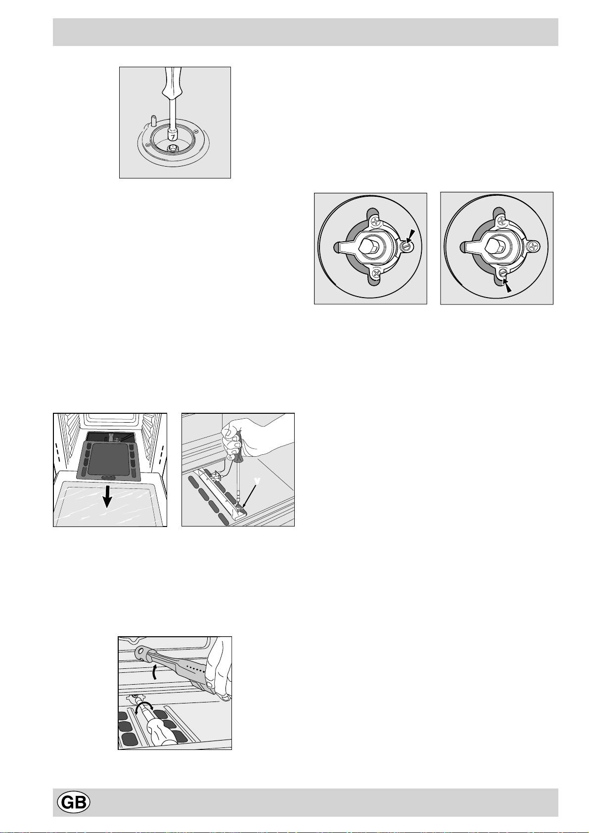
b) Regulating the minimum for the gas oven burner with
thermostat:
• Light the burner as described in the paragraph “The Oven
Knob” in the instruction booklet;
• urn the knob first to the Max setting for about 10 minutes
and then to Min;
• Remove the knob;
• Adjust the screw located outside the thermostat pin
until the flame is small but steady;
N.B.: In the case of liquid gas, the adjustment screw
must be screwed all the way in.
c) Minimum regulation of the hob burners:
•
Turn the tap to minimum;
• Remove the knob and adjust the regulation screw, which
is positioned in or next to the tap pin, until the flame is
small but steady.
N.B.: In the case of liquid gas, the regulation screw
must be screwed in all the way.
• Check that the flame does not go out when you turn the
tap quickly from high to low.
d) Regulating the primary air of the burners: The primary air
of the burners does not need to be regulated.
• Check that the burner does not turn off when you turn
Adapting to different types of gas
the knob from Max to Min and when you open and close
In order to adapt the oven to a different type of gas with
the oven door quickly.
respect to the gas for which it was manufactured (indi-
Regulating the Primary Air for the Oven Burner
cated on the label), follow these simple steps:
The oven burner do not need to be regulated in terms of
a) Replacing the oven burner nozzle
primary air.
· open the oven door fully
· pull out the sliding oven bottom
Important
· unscrew the burner fastening screws
On completion of this operation, replace the old rating sticker
with one indicating the new type of gas used. This sticker is
available from our Service Centres.
Note
Should the pressure of the gas used be different (or vary)
from the recommended pressure, it is necessary to fit a
V
suitable pressure regulator onto the inlet pipe in
compliance with current National Regulations relative to
“regulators for channelled gas”.
· remove screw “V” and then the oven burner;
· Unscrew the oven burner nozzle using the special
socket spanner for the nozzles, or a 7 mm socket span-
ner, and replace it with a nozzle suited to the new type
of gas (see Table 1).
Take particular care handling the spark plug wires
and the thermocouple pipes.
· Replace all the parts, following the steps described
above in the reverse order.
16
Оглавление
- Avvertenze
- Installazione
- Caratteristiche dei bruciatori ed ugelli
- La cucina con forno gas
- Le diverse funzioni presenti nella cucina
- Consigli pratici per la cottura
- Consigli pratici per la cottura al forno
- Manutenzione ordinaria e pulizia della cucina
- Important
- Installation
- Burner and Nozzle Characteristics
- Cooker with Gas Oven
- The Various Features of the Cooker
- Practical Cooking Advice
- Practical Cooking Advice for the Oven
- Routine Maintenance and Cleaning
- Ïðåäóïðåæäåíèÿ
- Èíñòðóêöèè ïî ìîíòàæó
- Õàðàêòåðèñòèêè ãàçîâûõ ãîðåëîê è ôîðñóíîê
- Òåõíè÷åñêèå õàðàêòåðèñòèêè
- Ðàçíûå ôóíêöèè êóõîííîé ïëèòû
- Ïðàêòè÷åñêèå ñîâåòû ïî ïðèãîòîâëåíèþ áëþä
- Ðåãóëÿðíîå òåõíè÷åñêîå îáñëóæèâàíèå è ÷èñòêà êóõîííîé ïëèòû
- Ïðàêòè÷åñêèå ñîâåòû ïî ïðèãîòîâëåíèþ áëþä â äóõîâîì øêàôó
- Merloni Elettrodomestici
