Yamaha NS-SW700: CONTROLS AND THEIR FUNCTIONS
CONTROLS AND THEIR FUNCTIONS: Yamaha NS-SW700
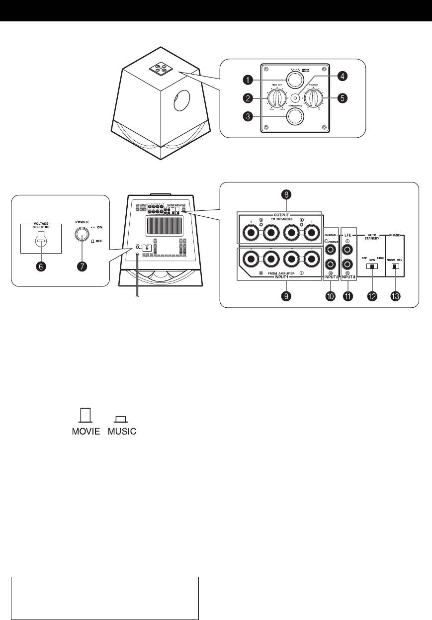
CONTROLS AND THEIR FUNCTIONS
Top panel
Front panel
Rear panel
(General model)
1 B.A.S.S. (Bass Action Selector System) button
4 Power indicator
When this button is pressed in to the MUSIC position,
Lights up in green while the subwoofer is on.
the bass sound in audio software is well reproduced.
Lights up in red while the subwoofer is set in the
By pressing the button again so that it pops out at the
standby mode by the operation of the automatic power-
MOVIE position, the bass sound in video software is
switching function.
well reproduced.
Goes off when the subwoofer is set in the standby
mode.
5 VOLUME control
Adjusts the volume level. Turn the control clockwise to
increase the volume, and counterclockwise to decrease
2 HIGH CUT control
the volume.
Adjusts the high frequency cut off point.
6 VOLTAGE SELECTOR switch
Frequencies higher than the frequency selected by this
(Asia and General models only)
control are all cut off (and no output).
If the preset setting of the switch is incorrect, set the
* One graduation of this control represents 10 Hz.
switch to the proper voltage (110/120/220/230-240V)
3 STANDBY/ON button
of your area.
Press this button to turn on the power when the
Consult your dealer if you are unsure of the correct
POWER switch is set in the ON position. (The power
setting.
indicator lights up in green.)
WARNING
Press again to set the subwoofer in the standby mode.
Be sure to unplug the subwoofer before setting the
(The power indicator goes off.)
VOLTAGE SELECTOR switch correctly.
Standby mode
The subwoofer is still using a small amount of
power in this mode.
4 En

CONTROLS AND THEIR FUNCTIONS
7 POWER switch
Set this switch to the ON position to use the subwoofer.
In this state, you can turn on the subwoofer or turn the
subwoofer into the standby mode by pressing the
STANDBY/ON button. Set this switch to the OFF
position to completely cut off the subwoofer’s power
supply from the AC outlet.
8 OUTPUT (TO SPEAKERS) terminals
Can be used for connecting to the main speakers.
Signals from the INPUT1 terminals are sent to these
terminals.
(Refer to “CONNECTIONS” for details.)
9 INPUT1 (FROM AMPLIFIER) terminals
Used to connect the subwoofer with the speaker
terminals of the amplifier.
(Refer to “CONNECTIONS” for details.
0 INPUT2 terminals
Used to input line level signals from the amplifier.
(Refer to “CONNECTIONS” for details.)
A INPUT3 (LFE) terminals
The HIGH CUT control 2 has no effect on the signals
inputted to these terminals. (See Page 7 for details)
B AUTO STANDBY (HIGH/LOW/OFF) switch
This switch is originally set to the OFF position. By
setting this switch to the HIGH or LOW position, the
subwoofer’s automatic power-switching function
operates, as described on page 11. If you do not need
this function, leave this switch in the OFF position.
* Make sure to change the setting of this switch only
when the subwoofer is set in the standby mode by
pressing the STANDBY/ON button.
C PHASE switch
This switch is to be set to the REV (reverse) position.
However, depending on your speaker system or
listening condition, there may be a case when better
sound quality is obtained by setting this switch to the
NORM (normal) position. Select the best position by
ear.
English
5 En
Оглавление
- CAUTION: Read this before operating your unit
- CONTENTS FEATURES
- SUPPLIED ACCESSORIES
- PLACEMENT
- CONTROLS AND THEIR FUNCTIONS
- CONNECTIONS
- AUTOMATIC POWER-SWITCHING FUNCTION
- ADJUSTING THE SUBWOOFER BEFORE USE
- ADVANCED YAMAHA ACTIVE SERVO TECHNOLOGY II
- TROUBLESHOOTING
- SPECIFICATIONS
- ATTENTION : Tenir compte des précautions ci-dessous avant de faire fonctionner l’appareil.
- TABLE DES MATIERES
- CARACTÉRISTIQUES ACCESSOIRES FOURNIS
- DISPOSITION
- PRÉSENTATION DES COMMANDES ET DE LEURS FONCTIONS
- BRANCHEMENTS
- FONCTION DE COMMUTATION D’ALIMENTATION AUTOMATIQUE
- RÉGLAGE DU CAISSON DE GRAVES AVANT UTILISATION
- ADVANCED YAMAHA ACTIVE SERVO TECHNOLOGY II
- RÉSOLUTION DES PROBLÈMES
- CARACTÉRISTIQUES TECHNIQUES
- ZUR BEACHTUNG: Bitte lesen Sie diese Bedienungs- anleitung vor Inbetriebnahme des Geräts durch.
- INHALT
- BESONDERHEITEN MITGELIEFERTES
- AUFSTELLUNG
- BEDIENUNGSELEMENTE UND IHRE FUNKTIONEN
- ANSCHLÜSSE
- AUTOMATISCHE EINSCHALTFUNKTION
- EINSTELLUNG DES SUBWOOFERS VOR DER INBETRIEBNAHME
- ADVANCED YAMAHA ACTIVE SERVO TECHNOLOGY II
- STÖRUNGSSUCHE
- TECHNISCHE DATEN
- FÖRSIKTIGT: Läs dessa anvisningar innan du börjar använda enheten.
- INNEHÅLL
- EGENSKAPER MEDFÖLJANDE TILLBEHÖR
- PLACERING
- REGLAGE OCH DERAS FUNKTIONER
- ANSLUTNINGAR
- AUTOMATISK PÅSLAGNING/AVSTÄNGNING
- JUSTERING AV SUBWOOFERHÖGTALAREN INNAN BRUK
- ADVANCED YAMAHA ACTIVE SERVO TECHNOLOGY II
- FELSÖKNING
- TEKNISKA DATA
- AVVERTENZA: Prima di cominciare ad usare l’apparecchio leggere quanto segue.
- INDICE
- CARATTERISTICHE ACCESSORI IN DOTAZIONE
- POSIZIONAMENTO
- COMANDI E RELATIVE FUNZIONI
- CONNESSIONI
- FUNZIONE DI ATTIVAZIONE AUTOMATICA
- REGOLAZIONE DEL SUBWOOFER PRIMA DELL’USO
- ADVANCED YAMAHA ACTIVE SERVO TECHNOLOGY II
- RISOLUZIONE DEI PROBLEMI
- SPECIFICHE TECNICHE
- PRECAUCIÓN: Leer este manual de instrucciones antes de poner la unidad en funcionamiento.
- CONTENIDO
- CARACTERÍSTICAS ACCESORIOS
- UBICACIÓN
- CONTROLES Y SUS FUNCIONES
- CONEXIONES
- FUNCIÓN DE CONMUTACIÓN AUTOMÁTICA DE LA ALIMENTACIÓN
- AJUSTE DEL ALTAVOZ DE ULTRAGRAVES ANTES DE UTILIZARLO
- ADVANCED YAMAHA ACTIVE SERVO TECHNOLOGY II
- LOCALIZACIÓN DE AVERÍAS
- ESPECIFICACIONES
- LET OP: lees eerst deze aanwijzingen alvorens het apparaat in gebruik te nemen.
- INHOUD
- KENMERKEN BIJGELEVERDE
- OPSTELLING
- BEDIENINGSELEMENTEN EN HUN FUNCTIES
- AANSLUITINGEN
- AUTOMATISCHE IN-/UITSCHAKELING
- INSTELLING VAN DE SUBWOOFER VOOR GEBRUIK
- ADVANCED YAMAHA ACTIVE SERVO TECHNOLOGY II
- VERHELPEN VAN PROBLEMEN
- SPECIFICATIES
- Предупреждение: внимательно изучите зто перед использованием аппарата.
- СОДЕРЖАНИЕ
- СВОЙСТВА ПРИЛАГАЕМЫЕ
- РАСПОЛОЖЕНИЕ
- ЭЛЕМЕНТЫ УПРАВЛЕНИЯ И ИХ ФУНКЦИИ
- ПОДКЛЮЧЕНИЕ
- ФУНКЦИЯ АВТОМАТИЧЕСКОГО ПЕРЕКЛЮЧЕНИЯ ПИТАНИЯ
- РЕГУЛИРОВКА САБВУФЕРА ПЕРЕД ИСПОЛЬЗОВАНИЕМ
- УСОВЕРШЕНСТВОВАННАЯ ТЕХНОЛОГИЯ ADVANCED YAMAHA ACTIVE SERVO TECHNOLOGY II
- ПОИСК И УСТРАНЕНИЕ НЕИСПРАВНОСТЕЙ
- ТЕХНИЧЕСКИЕ ХАРАКТЕРИСТИКИ


