Kenwood DMX100: Installation
Installation: Kenwood DMX100
Installation
to which they correspond. The unit may be damaged
Before Installation
or fail to work if you share the ¤ wires or ground
Before installation of this unit, please note the
them to any metal part in the car.
following precautions.
• When only two speakers are being connected to
#WARNINGS
the system, connect the connectors either to both
• If you connect the ignition wire (red) and the battery
the front output terminals or to both the rear output
wire (yellow) to the car chassis (ground), you may
terminals (do not mix front and rear). For example,
cause a short circuit, that in turn may start a fire.
if you connect the ¢ connector of the left speaker
Always connect those wires to the power source
to a front output terminal, do not connect the ¤
running through the fuse box.
connector to a rear output terminal.
• Do not cut out the fuse from the ignition wire (red)
• After the unit is installed, check whether the brake
and the battery wire (yellow). The power supply must
lamps, blinkers, wipers, etc. on the car are working
be connected to the wires via the fuse.
properly.
• Mount the unit so that the mounting angle is 30° or
#CAUTION
less.
• Install this unit in the console of your vehicle.
• Do not press hard on the panel surface when installing
Do not touch the metal part of this unit during and
the unit to the vehicle. Otherwise scars, damage, or
shortly after the use of the unit. Metal part such as the
failure may result.
heat sink and enclosure become hot.
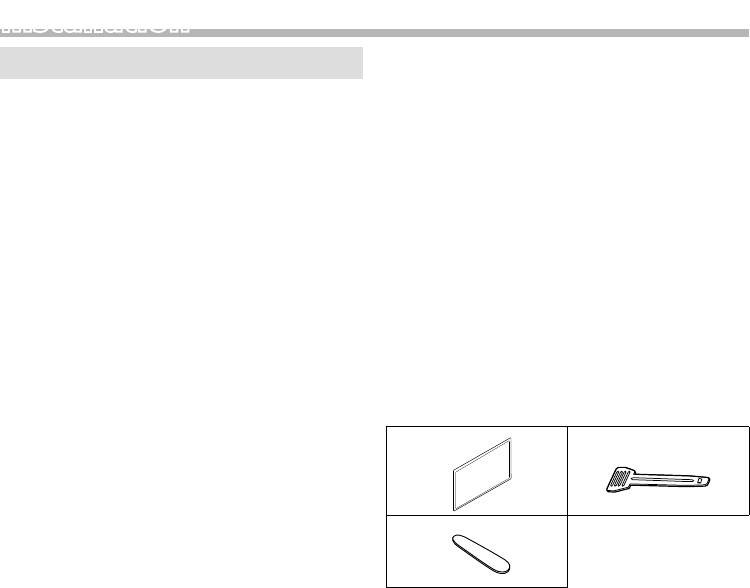
Ñ Supplied accessories for installation
✎ NOTE
• Mounting and wiring this product requires skills and
1
2
experience. For best safety, leave the mounting and
wiring work to professionals.
x2
• Make sure to ground the unit to a negative 12V DC
x1
power supply.
3
• Do not install the unit in a spot exposed to direct
sunlight or excessive heat or humidity. Also avoid
places with too much dust or the possibility of water
x1
splashing.
• Do not use your own screws. Use only the screws
Ñ Installation procedure
provided. If you use the wrong screws, you could
1) To prevent a short circuit, remove the key from
damage the unit.
the ignition and disconnect the ¤ terminal of the
• If the power is not turned ON (“There is an error in
battery.
the speaker wiring. Please check the connections.” is
2) Make the proper input and output wire connections
displayed), the speaker wire may have a short-circuit or
for each unit.
touched the chassis of the vehicle and the protection
3) Connect the wire on the wiring harness.
function may have been activated. Therefore, the
4) Take Connector B on the wiring harness and connect
speaker wire should be checked.
it to the speaker connector in your vehicle.
• If your car’s ignition does not have an ACC position,
5) Take Connector A on the wiring harness and connect
connect the ignition wires to a power source that
it to the external power connector on your vehicle.
can be turned on and off with the ignition key. If you
6) Connect the wiring harness connector to the unit.
connect the ignition wire to a power source with a
7) Install the unit in your car.
constant voltage supply, such as with battery wires,
8) Reconnect the ¤ terminal of the battery.
the battery may be drained.
9) Press the reset button.
• If the console has a lid, make sure to install the unit so
that the front panel will not hit the lid when closing
and opening.
• If the fuse blows, first make sure the wires aren’t
touching to cause a short circuit, then replace the old
fuse with one with the same rating.
• Insulate unconnected wires with vinyl tape or other
similar material. To prevent a short circuit, do not
remove the caps on the ends of the unconnected
wires or the terminals.
• Connect the speaker wires correctly to the terminals
English |
13
Installation
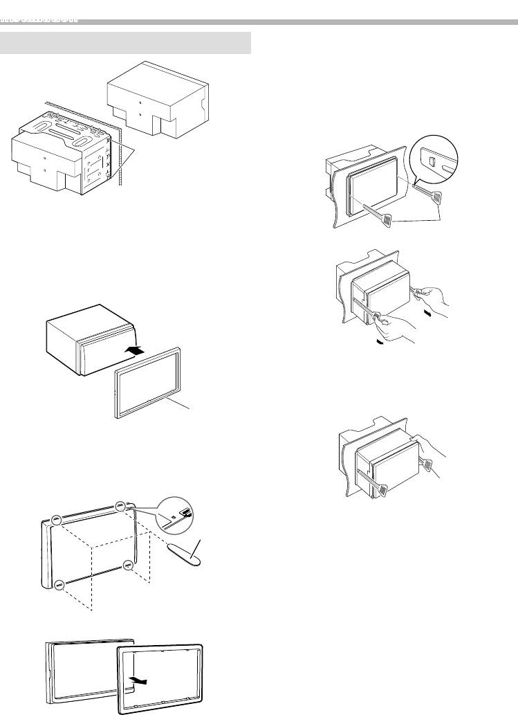
Installing the unit
Ñ Removing the unit
1) Remove the trim plate by referring to step 1 in
“Removing the trim plate”.
2) Insert the two extraction key (accessory 2) deeply
into the slots on each side, as shown. (The protrusion
at the tip of the extraction key must face toward the
unit.)
Bend the tabs of the
mounting sleeve with
a screwdriver or similar
utensil and attach it in
place.
✎ NOTE
2
• Make sure that the unit is installed securely in place. If
the unit is unstable, it may malfunction (eg, the sound
3) Pull out the unit halfway.
may skip).
Ñ Trim plate
1) Attach accessory 1 to the unit.
✎ NOTE
• Be careful to avoid injury from the catch pins on the
extraction key.
4) Pull the unit all the way out with your hands, being
careful not to drop it.
1
Ñ Removing the trim plate
1) Use the extraction key (accessory 3) to lever out the
four tabs (two on the upper part, two on the lower
part).
3
2) Pull the trim plate forward.
14
Installation
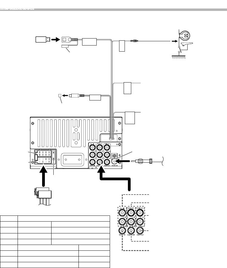
Ñ Connecting wires to terminals
Light Green
[1]
(Parking sensor wire)
USB terminal
(0.8 m)
Connect to the
(Extension cable)
[2]
USB device
vehicle’s parking
5V
=
1A
For best safety, be
brake detection
BRAKE
PARKING
sure to connect the
switch harness.
Cap
parking sensor.
Purple/White
(Reverse sensor wire)
Connect to vehicle’s reverse lamp harness
when using the optional rear view camera.
REVERSE
GEAR
SIGNAL
Subwoofer Preout
SUB
WOOFER
Light Blue/Yellow
Cap
(Steering remote control wire)
To steering remote
To use the steering wheel remote control
STEERING
WHEEL
REMOTE
CONTROL
feature, you need an exclusive remote
adapter (not supplied) matched to your car.
1 3 5 7
FM/AM antenna input
Connector B
2 4 6 8
1 3 5 7
2 4 6 8
FM/AM antenna
Connector A
Fuse (15A)
AV-IN audio input
ISO Connector
(Left; White, Right; Red)
Rear Audio Preout
(Left; White, Right; Red)
Ñ Wiring harness connector function guide
Front Audio Preout
Pin Color and function
(Left; White, Right; Red)
A-4 Yellow Battery
A-5 Blue/White Power Control
Visual Output (Yellow)
A-7 Red Ignition (ACC)
A-8 Black Earth (Ground) Connection
Rear view camera input (Yellow)
B-1/ B-2 Purple (+) / Purple/Black (–) Rear Right
AV-IN visual input (Yellow)
B-3/ B-4 Gray (+) / Gray/Black (–) Front Right
B-5/ B-6 White (+) / White/Black (–) Front Left
B-7/
B-8 Green (+) / Green/Black (–) Rear Left
[1]
• Speaker Impedance: 4-8 Ω
USB maximum power supply current : DC 5 V = 1 A
[2]
Sold separately
! CAUTION
Before you connect the commercially available ISO
connectors to the unit, check the following condition:
• Make sure that the pin assignment of the connector
matches with the KENWOOD unit.
• Take extra notice of the power wire.
• In case battery wire and ignition wire are not
corresponding then change them accordingly.
• In case the car does not have an ignition wire, use a
commercially available interface.
English |
15
Оглавление
- Contents Before use
- Getting Started
- Radio
- External Components
- Controlling Audio
- Installation
- About this Unit
- Содержание Перед эксплуатацией
- Приступая к работе
- Радио
- Внешние устройства
- Управление аудио
- Установка
- Информация об устройстве
- Зміст Перед використанням
- Запуск
- Радіо
- Зовнішні компоненти
- Керування звуком
- Встановлення
- Інформація про пристрій


