Indesit KN6C61X: Installation
Installation: Indesit KN6C61X
GB
13
!
Before operating your new appliance please read
this instruction booklet carefully. It contains important
information concerning the safe installation and
operation of the appliance.
!
Please keep these operating instructions for future
reference. Make sure that the instructions are kept with
the appliance if it is sold, given away or moved.
!
The appliance must be installed by a qualified
professional in accordance with the instructions
provided.
!
Any necessary adjustment or maintenance must be
performed after the cooker has been disconnected
from the electricity supply.
Positioning and levelling
!
It is possible to install the appliance alongside
cupboards whose height does not exceed that of the
hob surface.
!
Make sure that the wall in contact with the back of
the appliance is made from a non-flammable, heat-
resistant material (T 90°C).
To install the appliance correctly:
• Place it in the kitchen, the dining room or the bed-
sit (not in the bathroom).
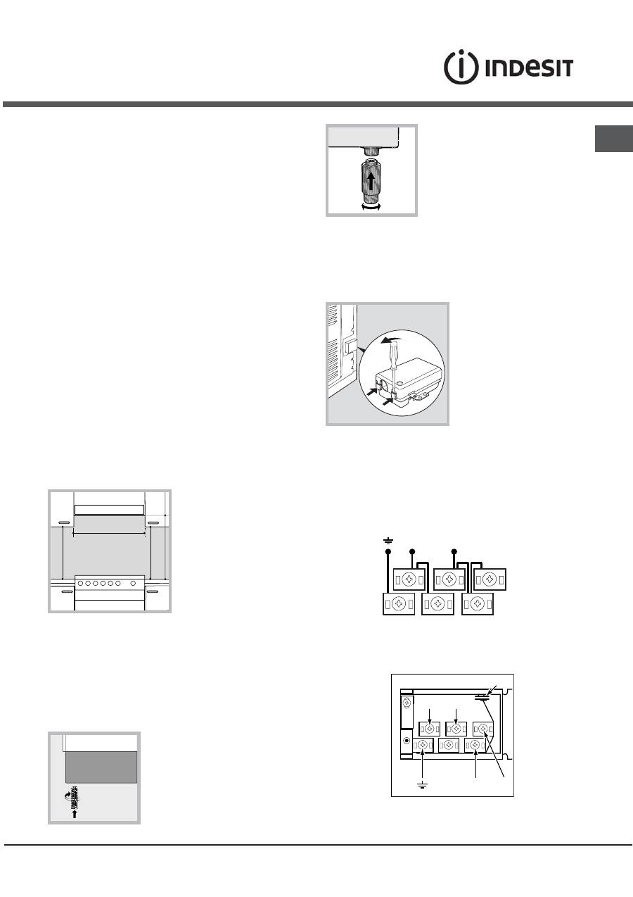
• If the top of the hob
is higher than the
cupboards, the
appliance must be
installed at least 600
mm away from them.
• If the cooker is
installed underneath a
wall cabinet, there must
be a minimum distance
of 420 mm between this
cabinet and the top of the hob.
This distance should be increased to 700 mm if the
wall cabinets are flammable (
see figure
).
• Do not position blinds behind the cooker or less
than 200 mm away from its sides.
• Any hoods must be installed according to the
instructions listed in the relevant operating manual.
Levelling
If it is necessary to level the
appliance, screw the
adjustable feet into the places
provided on each corner of the
base of the cooker (
see figure
).
The legs* fit into the slots on
the underside of the base of
the cooker.
Electrical connection
Fitting the power supply cable
To open the terminal board:
• Insert a screwdriver into the side tabs of the
terminal board cover.
• Pull the cover to
open it.
To install the cable, follow the instructions below:
• Loosen the cable clamp screw and the wire contact
screws.
!
The jumpers are pre-set at the Factory for 230 V
single-phase connection (
see figure
).
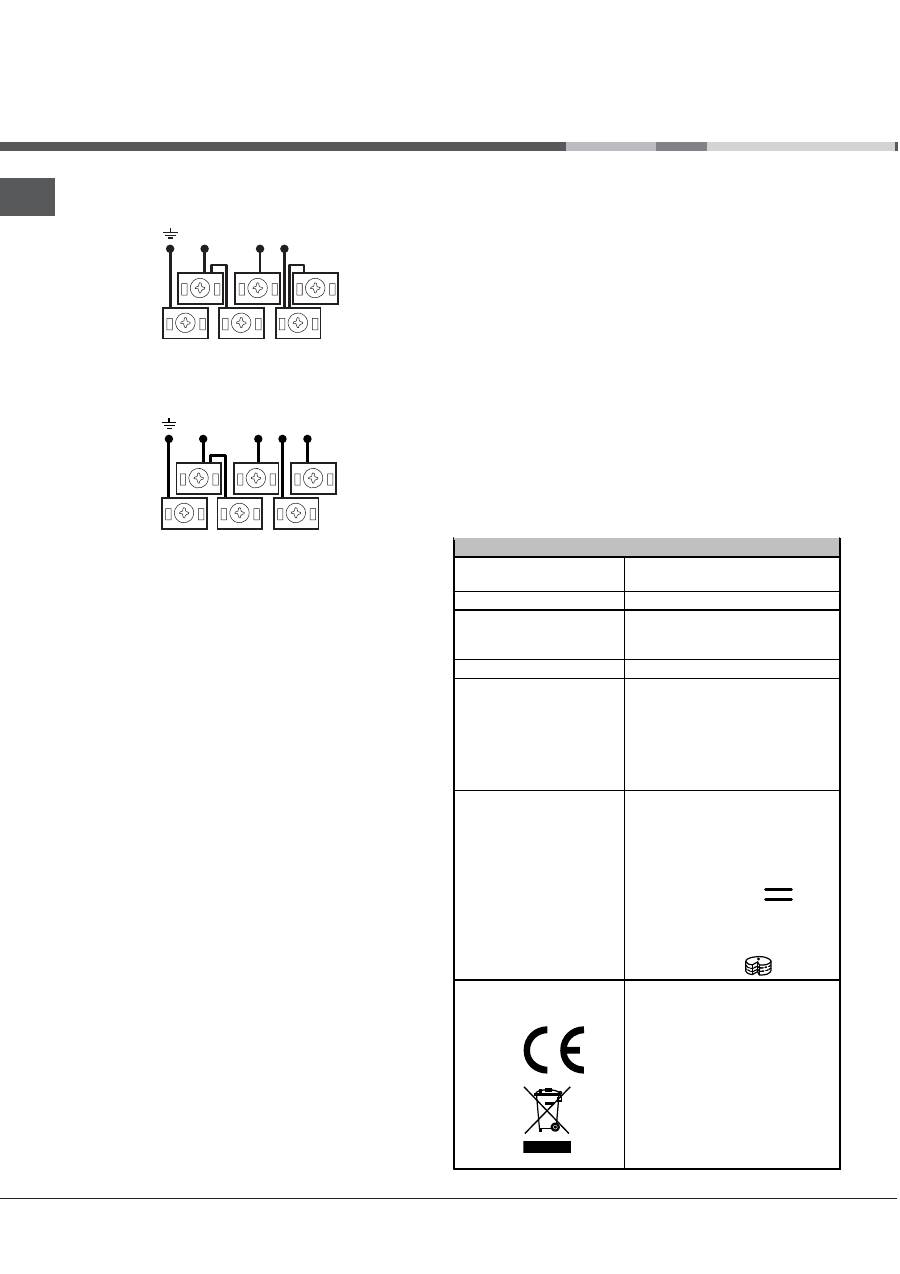
• To carry out the electrical connections as shown in
the figures, use the two jumpers inside the box (
see
figure
- labelled “P”).
Installation
HOOD
420
Min.
min.
650
mm. with hood
min.
700
mm. without hood
mm.
600
Min.
mm.
420
Min.
mm.
*
Only available in certain models.
N
L2
L1
L3
P
N
L
230V ~
H05RR-F 3x4 CEI-UNEL 35363
1
3
2
4
5
14
GB
N
L3
L1
L2
400V 3N~
H05RR-F 5x2.5 CEI-UNEL 35363
1
3
2
4
5
N
L2 L1
400V 2N~
H05RR-F 4x4 CEI-UNEL 35363
1
3
2
4
5
• Secure the power supply cable by fastening the
cable clamp screw then put the cover back on.
Connecting the supply cable to the electricity
mains
Install a standardised plug corresponding to the load
indicated on the appliance data plate (
see Technical
data table
).
The appliance must be directly connected to the
mains using an omnipolar switch with a minimum
contact opening of 3 mm installed between the
appliance and the mains. The switch must be suitable
for the charge indicated and must comply with current
electrical regulations (the earthing wire must not be
interrupted by the switch). The supply cable must be
positioned so that it does not come into contact with
temperatures higher than 50°C at any point.
Before connecting the appliance to the power supply,
make sure that:
• The appliance is earthed and the plug is compliant with
the law.
• The socket can withstand the maximum power of
the appliance, which is indicated by the data plate.
• The voltage is in the range between the values
indicated on the data plate.
• The socket is compatible with the plug of the
appliance. If the socket is incompatible with the
plug, ask an authorised technician to replace it. Do
not use extension cords or multiple sockets.
!
Once the appliance has been installed, the power
supply cable and the electrical socket must be easily
accessible.
!
The cable must not be bent or compressed.
!
The cable must be checked regularly and
replaced by authorised technicians only.
!
The manufacturer declines any liability should
these safety measures not be observed.
TABLE OF CHARACTERISTICS
Oven dimensions
(HxWxD)
32x43.5x40 cm
Volume
56 l
Useful measurements
relating to the oven
compartment
width 42 cm
depth 44 cm
height 8.5 cm
Voltage and frequency
see data plate
Ceramic hob
Front Left
Back Left
Back Right
Front Right
Max. ceramic hob
consumption
1700 W
1200 W
2100 W
1200 W
6200 W
ENERGY LABEL
Directive 2002/40/EC on the
label of electric ovens.
Standard EN 50304
Energy consumption for Natural
convection – heating mode:
Traditional mode
Declared energy consumption for
Forced convection Class –
heating mode:
Baking.
This appliance conforms to the
following European Economic
Community directives:
2006/95/EC dated 12/12/06 (Low
Voltage) and subsequent
amendments - 2004/108/EC
dated 15/12/04 (Electromagnetic
Compatibility) and subsequent
amendments - 93/68/EEC dated
22/07/93 and subsequent
amendments. 2002/96/EC
1275/2008 (Stand-by/Off mode)
Оглавление
- Installazione
- Descrizionedell’apparecchio
- Avvio e utilizzo
- Utilizzo del piano cotturavetroceramica
- Precauzioni e consigli
- Manutenzione e cura
- Assistenza
- Operating Instructions
- Installation
- Descriptionof the appliance
- Start-up and use
- Using the glass ceramic hob
- Precautions and tips
- Care and maintenance
- Mode d’emploi
- Installation
- Description de l’appareil
- Mise en marche et utilisation
- Utilisation du plan de cuissonvitrocéramique
- Précautions et conseils
- Nettoyage et entretien
- Руководство по эксплуатации
- Монтаж
- Описание изделия
- Включение и эксплуатация
- Стеклокерамическаяварочная панель
- Предосторожности и рекомендации
- Техническое обслуживание и уход
- Gebruiksaanwijzing
- Installatie
- Beschrijving van het apparaat
- Starten en gebruik
- Gebruik van de glaskeramischekookplaat
- Voorzorgsmaatregelen enadvies
- Onderhoud en verzorging
- Bedienungsanleitung
- Installation
- Beschreibung des Gerätes
- Inbetriebsetzung undGebrauch
- Nutzung des Glaskeramik-Kochfeldes
- Vorsichtsmaßregeln undHinweise
- Reinigung und Pflege
