Dell C__Dock II Expansion Station – страница 2
Инструкция к Ноутбуку Dell C__Dock II Expansion Station
Оглавление

0G913bk1.book Page 19 Thursday, October 18, 2001 12:33 PM
• Press the undock request button on the docking control base (see the
figure “Docking Control Base Controls and Indicators”). Wait for the
green docking light to turn off.
Replacing the Battery
Your docking device uses a lithium ion battery. The lithium ion cell battery
is a long-life battery, and it is very possible that you will never need to
replace it. However, should you need to replace it, perform the following
steps.
CAUTION: There is a danger of a new battery exploding if it is
incorrectly installed. Replace the battery only with the same or
equivalent type recommended by the manufacturer. Discard used
batteries according to the manufacturer’s instructions.
1
Undock the computer as described in “Undocking the Computer.”
2 Turn off the power switch on the docking device and disconnect the
AC adapter.
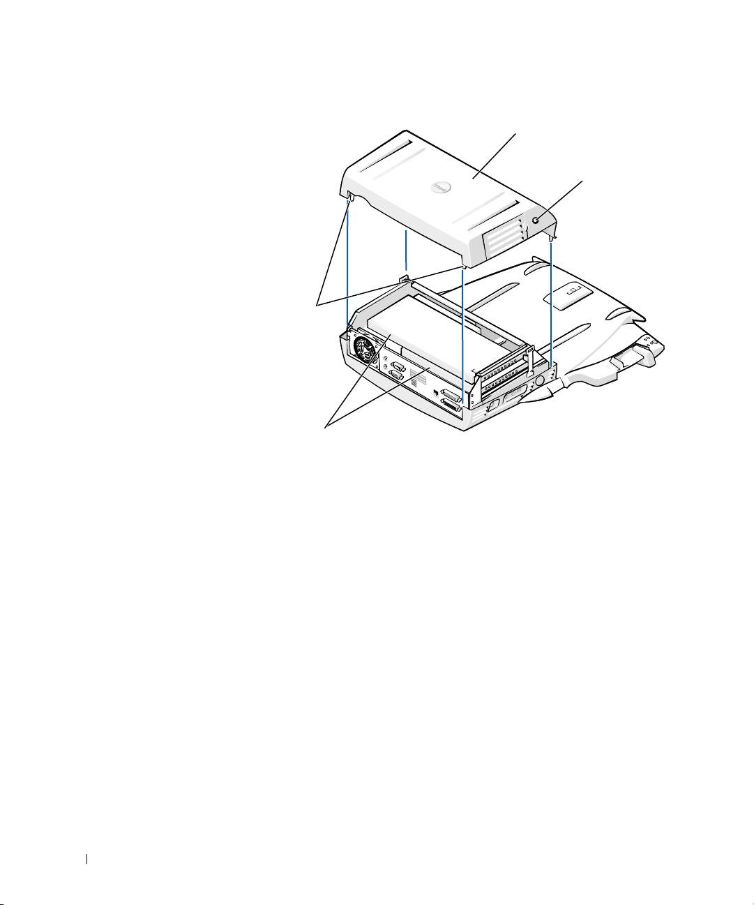
3 Remove the top cover by pressing the two side buttons and rotating
the cover toward the back of the expansion station (see “Removing the
Top Cover”). Once the cover is vertical, disengage the hinge tabs, and
fully remove the cover.
System Information Guide 19
0G913bk1.book Page 20 Thursday, October 18, 2001 12:33 PM
Removing the Top Cover
top cover
side buttons (2)
hinge tabs (2)
www.dell.com | support.dell.com
PCI cards (2)
4
Remove any installed cards from the expansion-card slots.
20 System Information Guide
Replacing the Battery
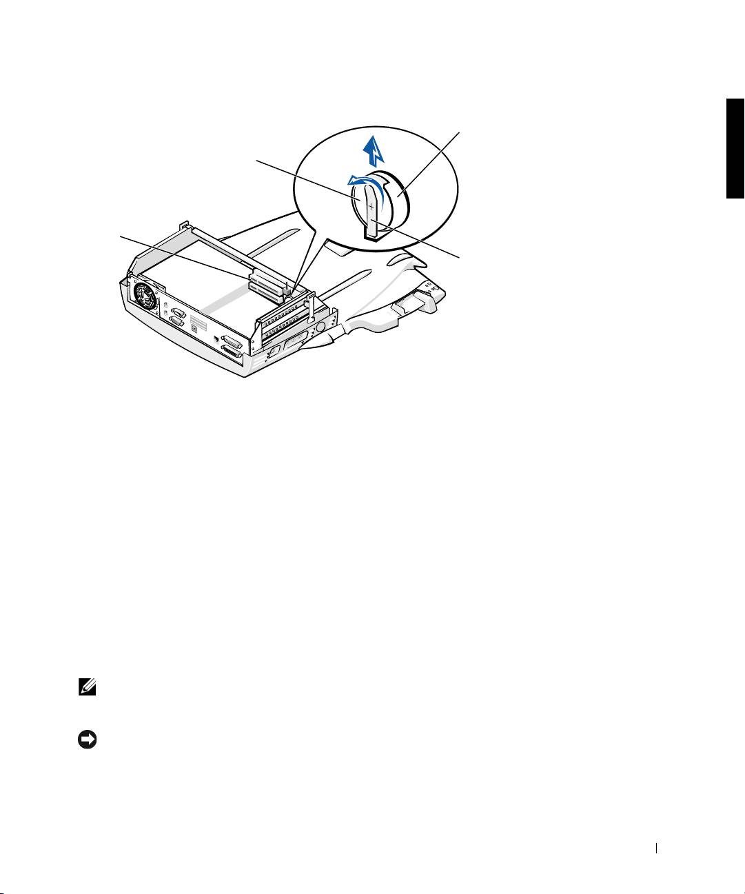
5
Slightly lift up the battery securing tab and remove the battery from
the battery socket.
6 Orient the new battery with the side labeled “+” facing up. Then
insert the battery into the socket and release the securing tab.
Do not dispose of this battery along with household waste. Contact your
local waste disposal agency for the address of the nearest battery deposit
site.
Removing and Installing a PCI
Expansion Card
To install a Peripheral Component Interconnect (PCI) expansion card in
the docking device, perform the following steps.
NOTE: Install 3.3-volt (V) or 5-V PCI expansion cards no longer than 10
inches (25.4 centimeters [cm]) in the top slot and install 3.3-V or 5-V PCI
expansion cards no longer than 6.9 inches (15.5 cm) in the bottom slot.
NOTICE: Do not touch or handle anything inside the docking device except
those objects mentioned in the following procedure. If you touch other objects,
you may damage the docking device, and may void your warranty.
System Information Guide 21
b
0G913bk1.book Page 21 Thursday, October 18, 2001 12:33 PM
attery
socket
battery
expansion-card
slots (2)
battery
securing
tab
0G913bk1.book Page 22 Thursday, October 18, 2001 12:33 PM
1 Save all files, close and exit all application programs, and exit the
operating system.
2 Turn off the computer.
3 Remove the monitor from the monitor stand. Remove the monitor
stand from the docking device.
4 Undock your computer and leave the eject/locking lever in the
unlocked position.
5 Detach all cables—including the AC adapter cable—from the docking
device. Make sure the eject/locking lever is not in the back/locking
position.
www.dell.com | support.dell.com
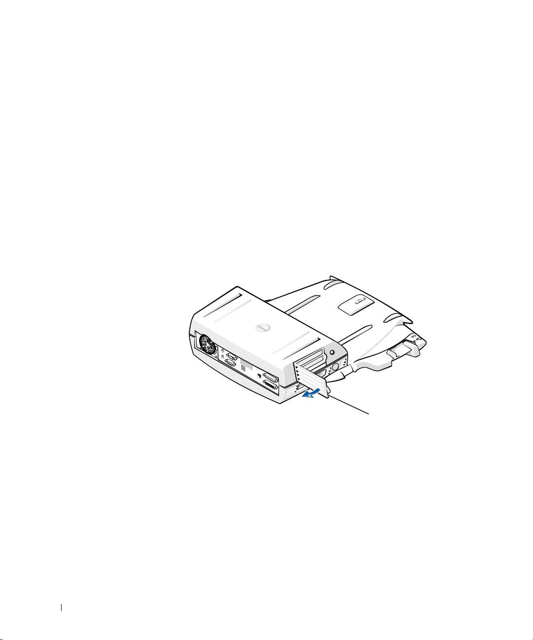
6 Press the latch on the PCI expansion-slot door and remove it. See the
following figure.
PCI Expansion-Slot Door and Expansion-Card Connector
PCI expansion-slot door
7
Remove the top cover by pressing the two side buttons and rotating
the cover toward the back of the docking device. Once the cover is
rotated back, disengage the hinge tabs from the back of the docking
device, and fully remove the top cover.
See the figure “Removing the Top Cover.”
22 System Information Guide

0G913bk1.book Page 23 Thursday, October 18, 2001 12:33 PM
8 Remove the screw holding the empty mounting bracket and set aside
for future use.
Remove the empty mounting bracket. If a PCI card is installed,
remove it by grasping the card by its outside corners, and easing it out
of its connector.
9 Install a PCI expansion card.
a Insert the card-edge connector of the card firmly into the
expansion-card connector.
b Gently rock the card side to side into the connector until it is fully
seated.
10 Reseat the screw in the PCI card bracket to secure the PCI card.
11 Replace the top cover by first engaging the hinge tabs and gently
lowering the front of the top cover into place. The top cover will be
properly aligned when you hear the side buttons click into place.
12 Reconnect the cables—including the AC adapter cable—you
disconnected in step 5.
13 Dock your computer.
14 Replace the monitor stand on the docking device and the monitor on
the monitor stand.
15 Turn on the computer.
16 Install the drivers for the PCI card.
If a 16/4 Token-Ring PCI Adapter network card came with the docking
device, Dell included a CD containing drivers and installation
instructions.
NOTE: If you are installing network drivers for a 16/4 Token-Ring PCI
Adapter network card, connect the computer to the network before you install
the drivers. Alert your network administrator before you connect the docking
device to a network.
If you are using a PCI card that was not purchased from Dell, use the
drivers and instructions provided by the manufacturer of the card.
NOTE: The 16/4 Token-Ring PCI Adapter network card that Dell installed has
been tested for use with the C/Dock II Expansion Station. Although you can
install other PCI expansion cards, Dell does not guarantee their functionality.
System Information Guide 23
0G913bk1.book Page 24 Thursday, October 18, 2001 12:33 PM
Using the C/Dock II Media Bay
You may use any media device from your computer, such as a floppy drive or
CD drive, in the C/Dock II Expansion Station media bay.
NOTICE: To avoid damaging the docking device or the media device, do not
install any device in the docking device media bay that you do not normally use
in your computer.
NOTICE: To avoid damaging the docking device, do not install the travel
module or battery from the Dell Latitude computer in the docking device media
bay.
To install the computer's media device in the docking device media bay,
www.dell.com | support.dell.com
perform the following steps.
NOTE: The eject/locking lever must be in the unlocked position before you
install a media bay device.
1
Save all files, close and exit all application programs, and exit the
operating system.
2 Turn off the computer.
3 Remove any media device in the docking device media bay.
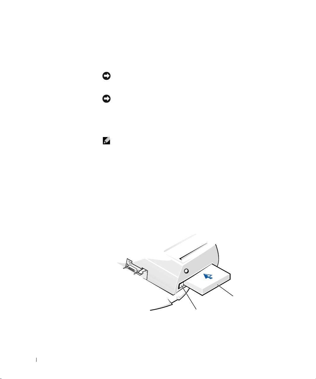
Press the media-bay eject button (see “Installing a Media Device in
the Media Bay”). After the device slides partially out of the media bay,
gently remove it the rest of the way.
Installing a Media Device in the Media Bay
media device
media-bay eject button
24 System Information Guide

0G913bk1.book Page 25 Thursday, October 18, 2001 12:33 PM
4 Insert the desired media device into the docking device media bay (see
the figure “Installing a Media Device in the Media Bay”).
5 Press the device in firmly.
If you properly seat the device, you should hear a click.
If you do not properly seat the device, it will be loose within the media
bay. Reseat the device.
6 Turn on the computer.
Installing a Media Device for Windows NT 4.0 With Softex
Docking Services
Windows NT with Softex Docking services allows hot-swapping of devices
from the media bay. For more information, see "Docking With Windows
NT and Softex Docking Services" and the Softex Docking Services User's
Guide at http://support.dell.com.
Securing the C/Dock Expansion Station
Security Features
The docking device has the following security features:
• An eject/locking lever that allows you to secure and eject your
computer. The back position secures the computer to the C/Dock II
Expansion Station. The middle position allows you to use the docking
device without securing it. The front position ejects the computer
from the docking device. Push the eject/locking lever to the back
position to use the padlock security lock and the security lock slot.
• A spring-loaded latch on the front of the base that fits into a security
slot on the bottom of the computer secures the computer to the
docking control base. Not all Dell portable computers have the
security slot.
• A secured top cover that blocks access to Peripheral Card Interconnect
(PCI) Card removal.
• A secured media-bay eject button that blocks removal of media bay
devices.
• An immobilized catch latch to deter unauthorized computer removal.
System Information Guide 25

0G913bk1.book Page 26 Thursday, October 18, 2001 12:33 PM
Securing the C/Dock II Expansion Station
Use one of the following methods to secure the docking device:
• Use a padlock alone or a padlock and looped security cable with the
padlock slot (see the figure “Docking Control Base Controls and
Indicators”) on the docking device.
A padlock alone blocks the eject lever and makes it difficult to detach
the computer from the docking device.
A security cable looped around a stationary object and used in
conjunction with the padlock can help prevent the unauthorized
movement of the computer and the C/Dock II Expansion Station.
www.dell.com | support.dell.com
• Attach a commercially available antitheft device to the security lock
slot (see the figure “Docking Control Base Controls and Indicators”)
on the docking device.
Antitheft devices usually include a segment of metal-stranded cable
with an attached locking device and associated key. Dell recommends
that you use a Kensington lock. For instructions on installing this kind
of antitheft device, see the documentation that accompanied the
device.
Dell Diagnostics
The Dell Diagnostics that came with your Dell Latitude computer includes
tests that help you troubleshoot the controllers in your docking device.
The subtests in the Network Interface test group of the Dell Diagnostics
verify the basic operation of the network controller in the docking device.
They test the controller's internal functions, including read and write access
to its registers and internal transmit and receive (loopback) capability.
The subtests in the Serial/Infrared Ports test group check the docking
device's interface with external devices (such as a serial mouse or a printer).
The subtests in this test group are not intended as a diagnostic test for the
external device itself.
The subtests in the USB test group check the docking device's interface
with external devices (such as a mouse). The subtests in this test group are
not intended as a diagnostic test for the external device itself.
For complete instructions on using the Dell Diagnostics, see your
computer's User's Guide.
26 System Information Guide

0G913bk1.book Page 27 Thursday, October 18, 2001 12:33 PM
Technical Specifications
Technical Specifications
Physical
Height:
With monitor stand 10.9 cm (4.3 inches)
Standalone 10.9 cm (4.3 inches)
Depth:
With monitor stand 50.0 cm (19.7 inches)
Standalone 47.0 cm(18.5 inches)
Width:
With monitor stand 43.5 cm (17.1 inches)
Standalone 42.0 cm (16.5 inches)
Weight:
With monitor stand 5.5 kg (12.0 lb)
Standalone 4.1 kg (9.0 lb)
Power
AC Adapter Input:
Voltage 100–240 VAC, 50–60 Hz
Amperage 1.5 A
C/Dock II Expansion Station
Input:
Voltage requires 20 VDC from AC Adapter
Amperage 3.5 A
I/O
Serial (DTE) 16550-compatible, 16-byte buffer connector
Parallel unidirectional, bidirectional, or ECP connector
PS/2 two mini-DIN connectors
USB two USB-compliant connectors
Infrared infrared port compatible with IrDA Standards
1.1 (Fast IR) and 1.0
System Information Guide 27

0G913bk1.book Page 28 Thursday, October 18, 2001 12:33 PM
Technical Specifications
Audio line out microphone-in jack; line-in/audio-in jack (for
record/playback devices); audio line-out jack
(for headphones)
SCSI Ultra SCSI, 50-pin, subminiature D connector
Video one connector
Network one RJ45 connector
Docking (to connect to
one connector
computer)
Ethernet Network Controller
www.dell.com | support.dell.com
®
Chip set 3Com
3C920; 10/100 BASE-TX (PC99-
compliant)
Data bus width 32-bit PCI host bus interface
IRQ IRQ10
SCSI Controller
Chip set Adaptec AIDC 7880C
Data bus width 8-bit SCSI bus; 32-bit PCI host bus interface
Data transfer rate 20 MB/sec
IRQ IRQ10
28 System Information Guide
0G913bk1.book Page 29 Thursday, October 18, 2001 12:33 PM
Safety and EMC Instructions: Portable
Computers
The following information defines the meaning of additional symbols used
only in the Safety and Electromagnetic Compatibility (EMC) Instructions.
Risk of explosion Aircraft
Risk of fire Use of this feature may be prohibited
on aircraft
Risk of electric shock
Safety Instructions
General
• When setting up the docking station for work, place it
on a level surface.
• Do not attempt to service the docking station yourself
unless you are an authorized service technician. Always
follow installation instructions closely.
• If you use an extension power cable with your AC
adapter, ensure that the total ampere rating of the
products plugged in to the extension power cable does
not exceed the ampere rating of the extension cable.
• Do not push objects into air vents or openings of your
computer. Doing so can cause fire or electric shock by
shorting out interior components.
System Information Guide 29
0G913bk1.book Page 30 Thursday, October 18, 2001 12:33 PM
• Place the AC adapter in a ventilated area, such as a desk
top or on the floor, when you use it to run the computer
or to charge the battery. Do not cover the AC adapter
with papers or other items that will reduce cooling; also,
do not use the AC adapter inside a carrying case.
• Do not use your computer in a wet environment, for
example, near a bath tub, sink, or swimming pool or in a
wet basement.
• To help avoid the potential hazard of electric shock, do
not connect or disconnect any cables or perform
www.dell.com | support.dell.com
maintenance or reconfiguration of this product during
an electrical storm. Do not use your computer during
an electrical storm unless all cables have been
disconnected and the computer is operating on battery
power.
• Use only the AC adapter and batteries that are
approved for use with this docking device as indicated
in this document. Use of another type of battery pack or
AC adapter may risk fire or explosion.
• Before you clean your docking station, turn it off and
disconnect the AC adapter from the electrical outlet.
Clean your docking station with a soft cloth dampened
with water. Do not use liquid or aerosol cleaners, which
may contain flammable substances.
30 System Information Guide
0G913bk1.book Page 31 Thursday, October 18, 2001 12:33 PM
Power (Safety Instructions)
• Use only the Dell-provided AC adapter approved for
use with this docking station. Use of another AC
adapter may cause a fire or explosion.
• Before you connect the docking station to an electrical
outlet, check the AC adapter voltage rating to ensure
that the required voltage and frequency match the
available power source.
• To remove power from the computer, turn it off and
disconnect the AC adapter from the electrical outlet.
• To help prevent electric shock, plug the AC adapter and
peripheral power cables into properly grounded power
sources. These power cables may be equipped with
three-prong plugs to provide an earth grounding
connection. Do not use adapter plugs or remove the
grounding prong from the power cable plug. If you use a
power extension cable, use the appropriate type, two-
prong or three-prong, to mate with the AC adapter
power cable.
• Be sure that nothing rests on your AC adapter’s power
cable and that the cable is not located where it can be
tripped over or stepped on.
• If you are using a multiple-outlet power strip, use
caution when plugging the AC adapter’s power cable
into the power strip. Some power strips may allow you
to insert the plug incorrectly. Incorrect insertion of the
power plug could result in permanent damage to your
computer, as well as risk of electric shock and/or fire.
Ensure that the ground prong of the power plug is
inserted into the mating ground contact of the power
strip.
System Information Guide 31

0G913bk1.book Page 32 Thursday, October 18, 2001 12:33 PM
Regulatory Notices
Electromagnetic Interference (EMI) is any signal or emission, radiated in
free space or conducted along power or signal leads, that endangers the
functioning of a radio navigation or other safety service or seriously
degrades, obstructs, or repeatedly interrupts a licensed radio
communications service. Radio communications services include but are
not limited to AM/FM commercial broadcast, television, cellular services,
radar, air-traffic control, pager, and Personal Communication Services
(PCS). These licensed services, along with unintentional radiators such as
digital devices, including computers, contribute to the electromagnetic
environment.
www.dell.com | support.dell.com
Electromagnetic Compatibility (EMC) is the ability of items of electronic
equipment to function properly together in the electronic environment.
While this computer has been designed and determined to be compliant
with regulatory agency limits for EMI, there is no guarantee that
interference will not occur in a particular installation. If this equipment
does cause interference with radio communications services, which can be
determined by turning the equipment off and on, you are encouraged to try
to correct the interference by one or more of the following measures:
• Reorient the receiving antenna.
• Relocate the computer with respect to the receiver.
• Move the computer away from the receiver.
• Plug the computer into a different outlet so that the computer and the
receiver are on different branch circuits.
If necessary, consult a Dell Technical Support representative or an
experienced radio/television technician for additional suggestions.
Dell computers are designed, tested, and classified for their intended
electromagnetic environment. These electromagnetic environment
classifications generally refer to the following harmonized definitions:
• Class A is typically for business or industrial environments.
• Class B is typically for residential environments.
32 System Information Guide

0G913bk1.book Page 33 Thursday, October 18, 2001 12:33 PM
Information Technology Equipment (ITE), including devices, expansion
cards, printers, input/output (I/O) devices, monitors, and so on, that are
integrated into or connected to the computer should match the
electromagnetic environment classification of the computer.
A Notice About Shielded Signal Cables: Use only shielded cables for
connecting devices to any Dell device to reduce the possibility of
interference with radio communications services. Using shielded cables
ensures that you maintain the appropriate EMC classification for the
intended environment. For parallel printers, a cable is available from Dell.
If you prefer, you can order a cable from Dell on the World Wide Web at
http://accessories.us.dell.com/.
Most Dell computers are classified for Class B environments. However, the
inclusion of certain options can change the rating of some configurations to
Class A. To determine the electromagnetic classification for your computer
or device, refer to the following sections specific for each regulatory agency.
Each section provides country-specific EMC/EMI or product safety
information.
CE Notice (European Union)
Marking by the symbol indicates compliance of this Dell computer to
the EMC Directive and the Low Voltage Directive of the European Union.
Such marking is indicative that this Dell system meets the following
technical standards:
• EN 55022 — “Limits and Methods of Measurement of Radio
Interference Characteristics of Information Technology Equipment.”
• EN 55024 — “Information technology equipment - Immunity
characteristics - Limits and methods of measurement.”
• EN 61000-3-2 — “Electromagnetic compatibility (EMC) - Part 3:
Limits - Section 2: Limits for harmonic current emissions (Equipment
input current up to and including 16 A per phase).”
• EN 61000-3-3 — “Electromagnetic compatibility (EMC) - Part 3:
Limits - Section 3: Limitation of voltage fluctuations and flicker in
low-voltage supply systems for equipment with rated current up to and
including 16 A.”
• EN 60950 — “Safety of Information Technology Equipment.”
NOTE: EN 55022 emissions requirements provide for two classifications:
• Class A is for typical commercial areas.
System Information Guide 33

0G913bk1.book Page 34 Thursday, October 18, 2001 12:33 PM
• Class B is for typical domestic areas.
This Dell device is classified for use in a typical Class B domestic
environment.
A "Declaration of Conformity" in accordance with the preceding directives
and standards has been made and is on file at Dell Computer Corporation
Products Europe BV, Limerick, Ireland.
Battery Disposal
Your docking device uses a lithium ion battery. The lithium ion battery is a
long-life battery, and it is very possible that you will never need to replace it.
www.dell.com | support.dell.com
However, should you need to replace it, see “Replacing the Battery” found
earlier in this document.
Do not dispose of the battery along with household waste. Contact your
local waste disposal agency for the address of the nearest battery deposit
site.
EN 55022 Compliance (Czech Republic Only)
This device belongs to Class B devices as described in EN 55022, unless
it is specifically stated that it is a Class A device on the specification
label. The following applies to devices in Class A of EN 55022 (radius of
protection up to 30 meters). The user of the device is obliged to take all
steps necessary to remove sources of interference to telecommunication
or other devices.
Pokud není na typovém štitku počítače uvedeno, že spadá do třídy
A podle EN 55022, spadá automaticky do třídy B podle EN 55022.
Pro zařízení zařazená do třídy A (ochranné pásmo 30m) podle EN
55022 platí následující. Dojde−li k rušení telekomunikačních nebo
jinych zařízení, je uživatel povinen provést taková opatření, aby
rušení odstranil.
34 System Information Guide

0G913bk1.book Page 35 Thursday, October 18, 2001 12:33 PM
Polish Center for Testing and Certification Notice
The equipment should draw power from a socket with an attached
protection circuit (a three-prong socket). All equipment that works together
(computer, monitor, printer, and so on) should have the same power supply
source.
The phasing conductor of the room’s electrical installation should have a
reserve short-circuit protection device in the form of a fuse with a nominal
value no larger than 16 amperes (A).
To completely switch off the equipment, the power supply cable must be
removed from the power supply socket, which should be located near the
equipment and easily accessible.
A protection mark "B" confirms that the equipment is in compliance with
the protection usage requirements of standards PN-93/T-42107 and PN-EN
55022: 1996.
Wymagania Polskiego Centrum Badań i Certyfikacji
Urządzenie powinno być zasilane z gniazda z przyłączonym obwodem
ochronnym (gniazdo z kołkiem). Współpracujące ze sobą urządzenia
(komputer, monitor, drukarka) powinny być zasilane z tego samego
źródła.
Instalacja elektryczna pomieszczenia powinna zawierać w przewodzie
fazowym rezerwową ochronę przed zwarciami, w postaci bezpiecznika
o wartości znamionowej nie większej ni 16A (amperów).
W celu całkowitego wyłączenia urządzenia z sieci zasilania, naley
wyjąć wtyczkę kabla zasilającego z gniazdka, które powinno
znajdować się w pobliu urządzenia i być łatwo dostępne.
Znak bezpieczeństwa "B" potwierdza zgodność urządzenia z
wymaganiami bezpieczeństwa uytkowania zawartymi w
PN−93/T−42107 i PN−EN 55022:1996.
Jeźeli na tabliczce znamionowej umieszczono informację, źe
urządzenie jest klasy A, to oznacza to, źe urządzenie w środowisku
mieszkalnym moźe powodować zaklócenia radioelektryczne. W takich
przypadkach moźna źądać od jego uźytkownika zastosowania
odpowiednich środków zaradczych.
System Information Guide 35

Pozostałe instrukcje bezpieczeństwa
•
www.dell.com | support.dell.com
CE Mark Notice
This device complies with the requirements of the European Directive
1999/5/EC.
36 System Information Guide
Ni
e na
l
e
y u
ywa
ć
w
t
ycze
k
a
d
ap
t
erowyc
h
l
u
b
usuwa
ć
k
o
łk
0G913bk1.book Page 36 Thursday, October 18, 2001 12:33 PM
a
obwodu ochronnego z wtyczki. Jeeli konieczne jest uycie
przedłuacza to naley uyć przedłuacza 3−yłowego z
prawidłowo połączonym przewodem ochronnym.
• System komputerowy naley zabezpieczyć przed nagłymi,
chwilowymi wzrostami lub spadkami napięcia, uywając
eliminatora przepięć, urządzenia dopasowującego lub
bezzakłóceniowego źródła zasilania.
• Naley upewnić się, aby nic nie leało na kablach systemu
komputerowego, oraz aby kable nie były umieszczone w miejscu,
gdzie mona byłoby na nie nadeptywać lub potykać się o nie.
• Nie naley rozlewać napojów ani innych płynów na system
komputerowy.
• Nie naley wpychać adnych przedmiotów do otworów systemu
komputerowego, gdy moe to spowodować poar lub poraenie
prądem, poprzez zwarcie elementów wewnętrznych.
• System komputerowy powinien znajdować się z dala od
grzejników i źródeł ciepła. Ponadto, nie naley blokować otworów
wentylacyjnych. Naley unikać kładzenia luźnych papierów pod
komputer oraz umieszczania komputera w ciasnym miejscu bez
moliwości cyrkulacji powietrza wokół niego.

0G913bk1.book Page 37 Thursday, October 18, 2001 12:33 PM
Základnová stanice Dell™ Latitude™ C/Dock II
Příručka k zařízení
www.dell.com | support.dell.com

0G913bk1.book Page 38 Thursday, October 18, 2001 12:33 PM
Poznámky, upozornění a výstrahy
POZNÁMKA: POZNÁMKA obsahuje dležité informace, které vám pomohou počítač lépe
využívat.
UPOZORNĚNÍ: UPOZORNNÍ ukazuje na možnost poškození hardwaru nebo ztráty dat
a sdluje vám, jak se problému vyhnout.
POZOR: Odstavec uvozený slovem POZOR označuje možnost poškození
majetku, zranění či smrtelného úrazu.
____________________
Informace v tomto dokumentu se mohou mnit bez pedchozího upozornní.
2001 Dell Computer Corporation. Všechna práva vyhrazena.
Jakákoli reprodukce bez písemného svolení společnosti Dell Computer Corporation je písn zakázána.
Ochranné známky použité v textu:
Dell
, logo
DELL
,
Latitude
a
DellWare
jsou ochranné známky společnosti Dell Computer
Corporation;
3Com
je ochranná známka společnosti 3Com Corporation;
Microsoft
,
Windows
a
Windows NT
jsou
registrované ochranné známky společnosti Microsoft Corporation.
Jiné ochranné známky a obchodní názvy pípadn použité v tomto dokumentu mohou odkazovat na subjekty držící
práva k tmto známkám a názvy jejich výrobk. Společnost Dell Computer Corporation odmítá vlastnické zájmy
k ochranným známkám a obchodním názvm mimo své vlastní.
Tento produkt obsahuje technologie chránné autorským právem a americkými patenty k metodám a jinými právy
k intelektuálnímu vlastnictví náležejícími společnosti Macrovision Corporation a jiným vlastníkm. Používání této
technologie musí být schváleno společností Macrovision Corporation a není-li touto společností stanoveno jinak,
je povoleno pouze pro účely domácího nebo jiného omezeného zobrazování. Dekódování ani rozbor kódu nejsou
povoleny.
Říjen 2001 P/N 0G913 Rev. A01
