Dell ETL: инструкция
Раздел: Бытовая, кухонная техника, электроника и оборудование
Тип: Компьютер
Инструкция к Компьютеру Dell ETL
Оглавление
- Dell Virtualization Solutions Engineering
- Table of Contents

Dell PowerVault MD3000i
Configuration Guide for
VMware ESX Server Software
January 2008
Dell Virtualization Solutions Engineering
www.dell.com/vmware
Dell Inc Page 1

Table of Contents
1. Introduction ................................................................................................................. 3
2. Architectural Setup ..................................................................................................... 3
3. iSCSI Connectivity Support ........................................................................................ 4
4. PowerVault MD3000i Storage Setup and Configuration ........................................... 4
5. iSCSI Software Initiator Configuration on ESX Server ............................................. 5
6. Configure iSCSI storage on ESX Server .................................................................... 8
7. References ................................................................................................................... 9
Dell Inc Page 2
1. Introduction
The Dell™ PowerVault™ MD3000i storage solution consists of a standard or high availability
configuration. The standard model has a single controller with two 1GbE ports. It can be deployed
to support up to 16 hosts non-redundantly. The high availability model has dual controllers with
two 1GbE ports per controller for a total of four 1GbE ports. The dual controller option can
connect up to 16 fully redundant hosts. This document provides instructions to setup the
MD3000i iSCSI storage solution for usage with VMware® ESX Server™ software.
The Dell PowerVault MD3000i iSCSI storage array contains four Ethernet ports through which the
VD can be accessed affording both redundancy and availability of data. Provisioning of storage
on servers in a VM environment is a multiple step process starting with definition of the server
names for host access. The iSCSI connection is then established from the storage subsystem,
and after detection and configuration is established as a two way link with the associated ESX
server(s), completing the iSCSI communication subsystem. The final step allocates the detected
storage to the individual virtual machines (VM’s), where all or part of the configured storage can
be assigned to individual VM’s.
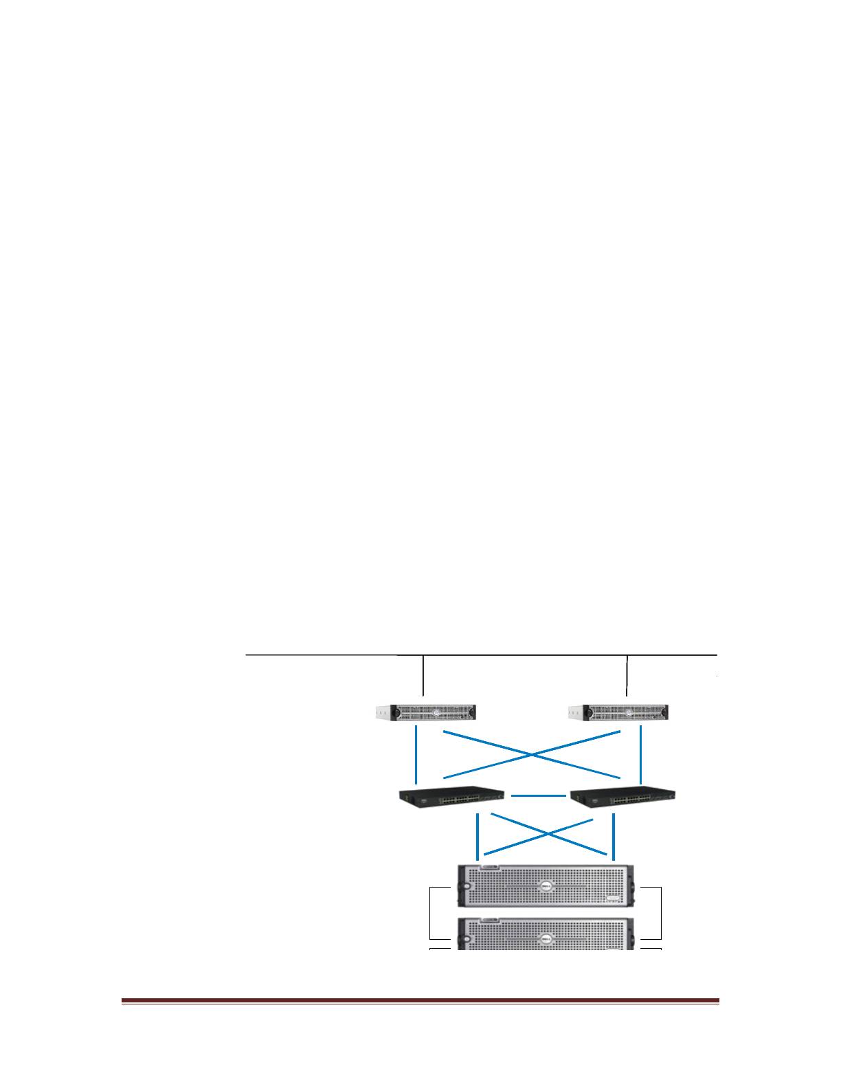
2. Architectural Setup
The following figure illustrates a typical high availability setup for using the MD3000i in an ESX
Server farm. As a best practice, Dell recommends using a separate Gigabit Ethernet network
switch to handle iSCSI storage traffic. Two servers are connected to two switches. Each switch
has a path to the MD3000i via the two dual port controllers. In this base HA configuration, the
servers, switches, and MD3000i ports share the same subnet. The NIC ports serving iSCSI
traffic on the ESX servers are teamed.
Figure 1: MD3000i High Availability Configuration
Dell Inc Page 3
LAN
LAN
LAN
LAN
ESX Server 2
ESX Server 2
ESX Server 2
ESX Server 2
ESX Server 1
ESX Server 1
ESX Server 1
ESX Server 1
Ethernet Switches
Ethernet Switches
Ethernet Switches
Ethernet Switches
MD3000i
MD3000i
MD3000i
MD3000i
MD1000
MD1000
MD1000
MD1000
MD1000
MD1000
MD1000
MD1000
3. iSCSI Connectivity Support
Dell Inc Page 4
Operating System
Host Bus Adapter
VMware ESX Server 3.5
iSCSI software initiator with ESX Server
4. PowerVault MD3000i Storage Setup and Configuration
Create virtual disks on MD3000i using steps described in:
http://support.dell.com/support/edocs/systems/md3000i/en/IG/PDF/IGbk0HR.pdf.
After opening the Modular Disk Storage Manager and selecting the MD3000i storage array to be
configured, select the Configure tab.
Note: in the examples to follow the Storage array “sg23_training” is an MD3000i with
virtual disks already configured using the Create Virtual Disks selection. The new server
being added to an existing host group is named “Valhalla”.
From the Configure tab
1. Select Configure Host Access (Manual).
2. Enter the host name for the server which has the ESX Server software is installed.
3. Select Linux as the host type.
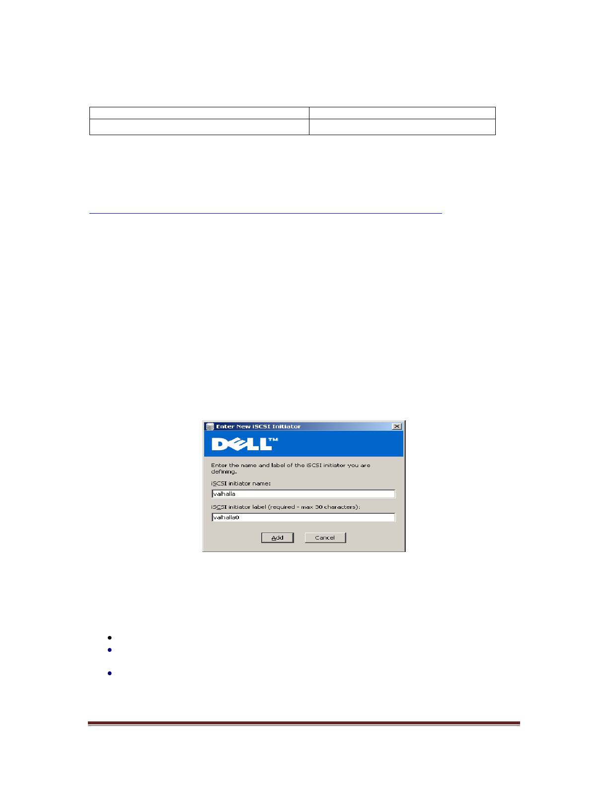
From the next screen, specify the iSCSI Initiator by selecting the New button (lower right on
screen). On the Enter New iSCSI Initiator screen enter a name for the iSCSI initiator name. The
label is auto-populated from the server name.
Figure 2: iSCSI Initiator Window
Host Group configuration starts from the following screen titled “Configure Host Access (Manual)
– Specify Host Group”. For ESX servers supporting VMotion, HA, and DRS, a host group must be
defined so the MD3000i storage subsystem has a configured iSCSI path to each of the hosts.
Select “Yes: This host will share access to the same virtual disks with other hosts”
If a new host group is desired select the radio button for that option and enter in a name
for your host group using standard host naming conventions (e.g. no spaces etc).
Should you already have one or more host groups assigned, select the radio button
enabling selection from a drop down list of existing host groups. This option is to be
used when configuring the second, third, etc. host in a group. Once the host group is
selected previously configured hosts for that host group will be displayed. Note that
these are shown as Linux hosts even though they are configured as ESX servers.
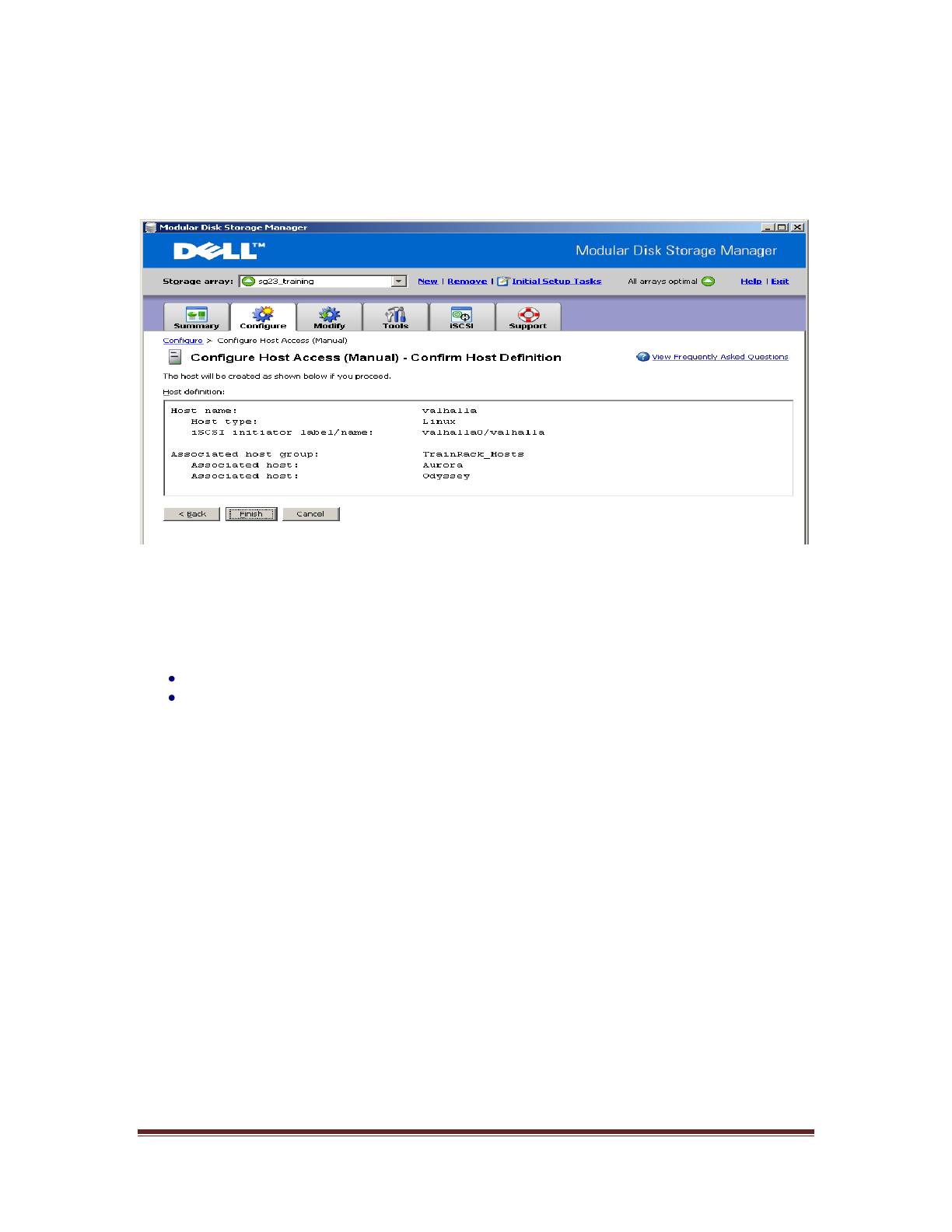
Selecting Next provides a Confirmation screen in which the new server being configured is shown
and the other previously configured associated hosts are named. For the first server configured
in a new host group there will be no associated hosts listed under the Associated host group.
Figure 3: Modular Disk Storage Manager Configure Tab
Select Finish confirming the new host definition. This initiates the wizard configuration of the new
host.
On completion,
Select Yes to proceed to the next host you wish to configure, or
Select No to end the configuration wizard.
Helpful Hint: Record the MD3000i IP address for later configuration
5. iSCSI Software Initiator Configuration on ESX Server
This section lists the steps required to configure the software initiator on the VMware ESX Server.
Connect to the ESX server/VirtualCenter using VI Client, and follow the below steps:
1. Select Configuration->Security Profile on the ESX server.
Dell Inc Page 5
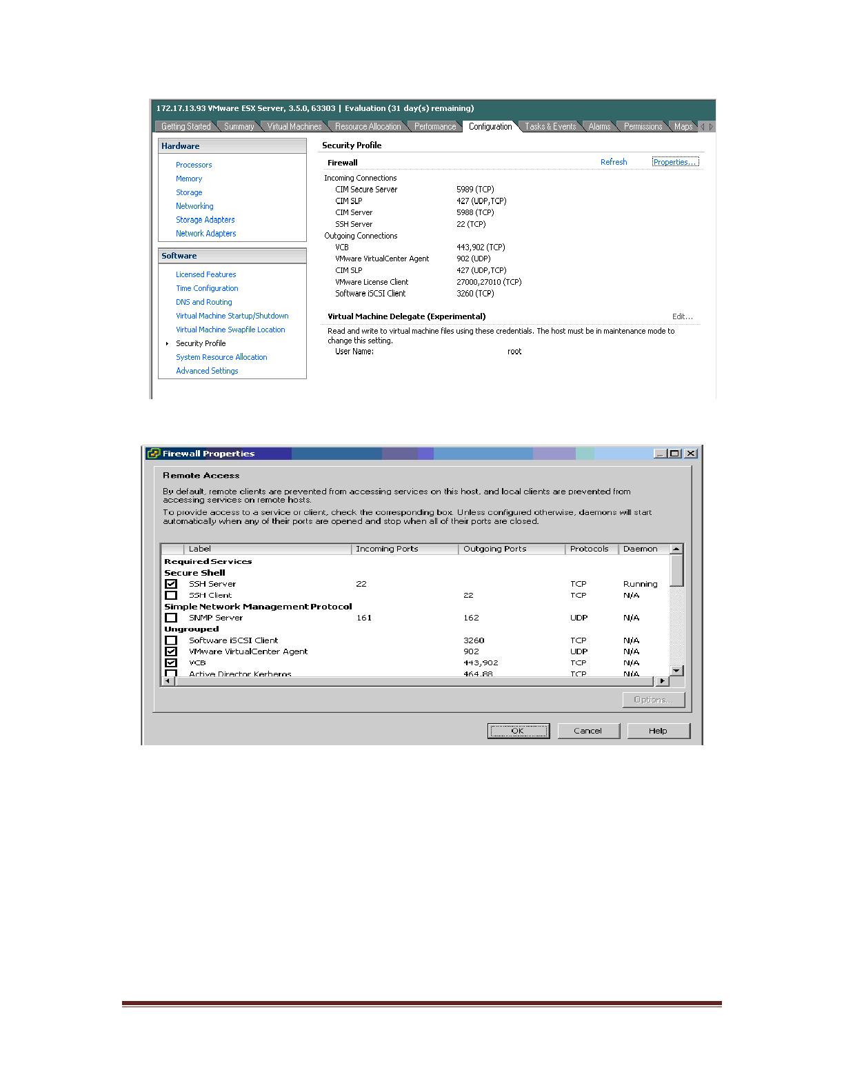
Figure 4: Security Profile Configuration Tab
2. Click on Properties. The Firewall Properties box appears.
Figure 5: Firewall Properties Window
3. Check Software iSCSI Client.
4. Select Configuration->Storage Adapters on the ESX server.
5. Select iSCSI software adapter and click on Properties.
Dell Inc Page 6
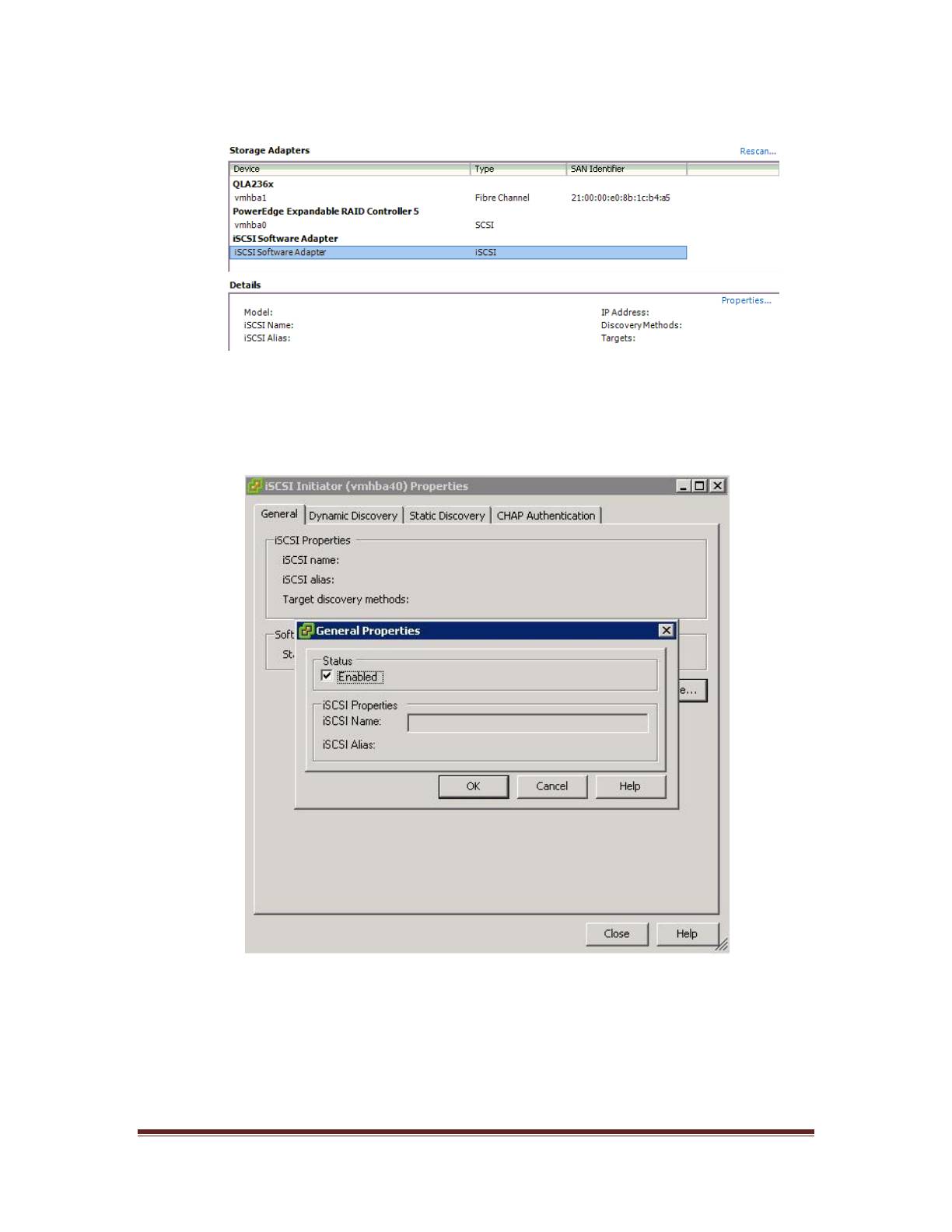
Figure 6: iSCSI software adapter under Storage Adapters on VI client
6. The iSCSI initiator Properties window appears.
7. Under the general tab select Configure tab. Select the Enabled checkbox and click OK.
Select Close.
Figure 7: iSCSI software initiator properties window
Dell Inc Page 7
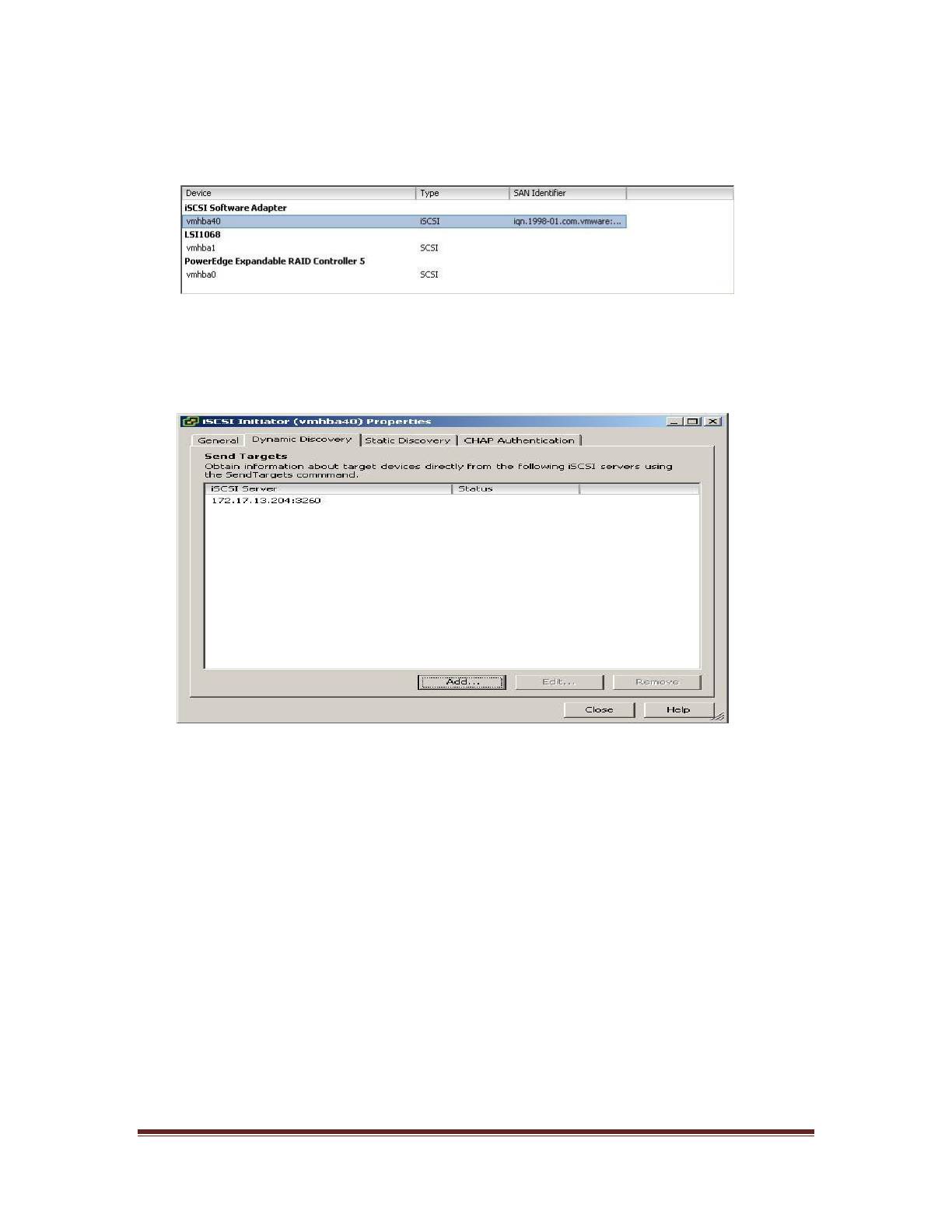
8. Select iSCSI software adapter under storage. You should now see your iSCSI Target
name listed.
Figure 8: iSCSI software adapter after initial configuration
9. Select Properties under storage adapters. Select Dynamic Discovery. Select Add.
Provide the IP address of the MD3000i and click OK. There may be a slight delay before
the process completes.
Figure 9: iSCSI software initiator properties window
10. Click Close.
6. Configure iSCSI storage on ESX Server
Connect to the ESX server/Virtual Center using VI Client and follow the steps below.
1. Go to the configuration tab and select Storage Adapters. Select the iSCSI Software
Adapter and click Rescan. The newly created iSCSI target and LUN should be visible
from the ESX server.
Dell Inc Page 8
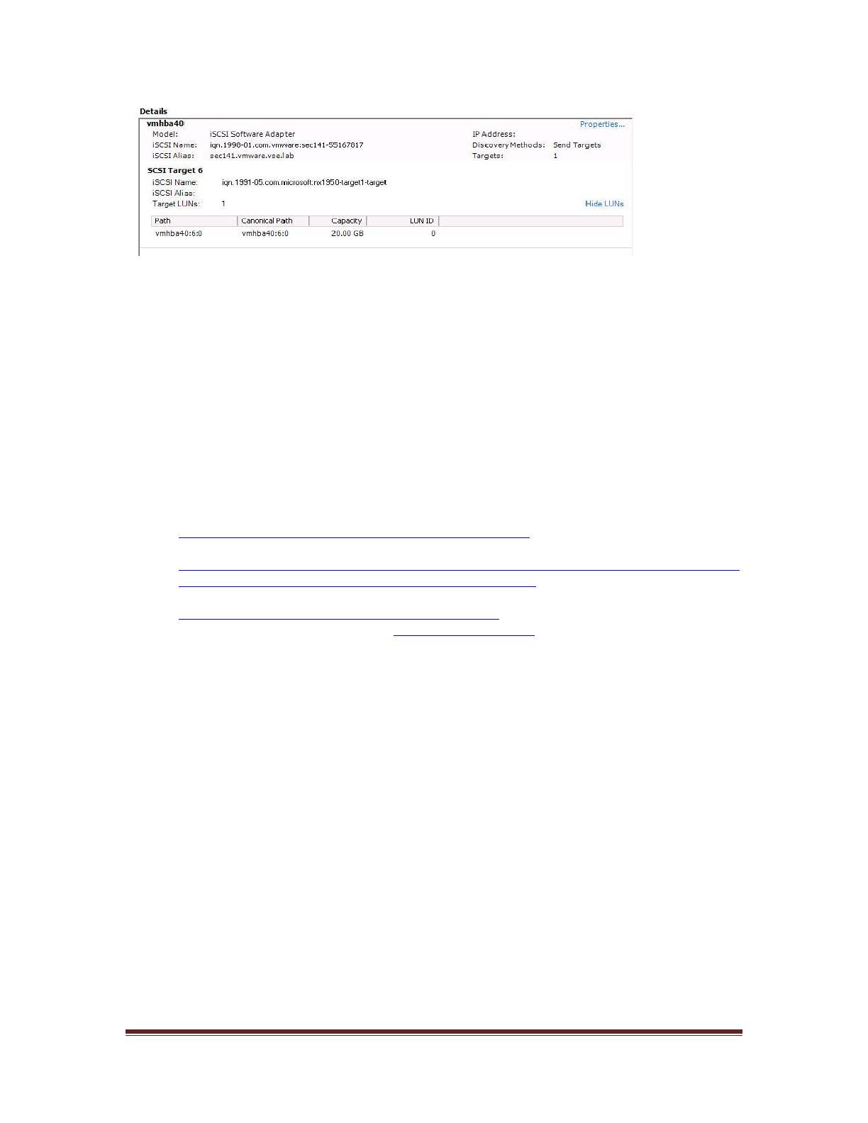
Figure 10: iSCSI target and LUNs as visible through VI client
2. Go to the configuration tab and select Storage. Click on Add Storage, select Disk/Lun
and click Next. Select the newly added storage and click Next.
3. Select the newly created iSCSI LUN and click Next.
4. Review the disk layout and click Next.
5. Provide a name for the VMFS datastore and click Next.
6. Select the appropriate block size and capacity for the VMFS datastore and click Next.
7. Review the disk layout and click Finish to create the VMFS datastore. The new datastore
is now ready to be used for storing virtual machine images.
7. References
1. Dell PowerVault MD3000i support documents:
http://support.dell.com/support/edocs/systems/md3000i/
2. Drivers download page for MD3000i:
http://support.dell.com/support/downloads/driverslist.aspx?c=us&cs=555&l=en&s=biz&Se
rviceTag=&SystemID=PWV_MD3000I&os=NAA&osl=EN
3. VMware Virtual Infrastructure 3 Documentation:
http://www.vmware.com/support/pubs/vi_pubs.html
4. Dell|VMware alliance home page: www.dell.com/vmware
Dell Inc Page 9

THIS DOCUMENT IS FOR INFORMATIONAL PURPOSES ONLY, AND MAY CONTAIN
TYPOGRAPHICAL ERRORS AND TECHNICAL INACCURACIES. THE CONTENT IS
PROVIDED AS IS, WITHOUT EXPRESS OR IMPLIED WARRANTIES OF ANY KIND.
Microsoft and Windows are registered trademarks of Microsoft Corporation. VMware is a registered
trademark and VMotion, Virtual SMP, and ESX Server are trademarks of VMware, Inc. Intel and Xeon are
registered trademarks of Intel Corp. Other trademarks and trade names may be used in this document to
refer to either the entities claiming the marks and names or their products. Dell disclaims proprietary interest
in the marks and names of others.
Copyright 2007 Dell Inc. All rights reserved. Reproduction in any manner whatsoever without the express
written permission of Dell Inc. is strictly forbidden. For more information, contact Dell. Information in this
document is subject to change without notice.
Dell Inc Page 10
