Dell POWEREDGE 1955: инструкция
Раздел: Профоборудование
Тип: Аппарат
Инструкция к Аппарату Dell POWEREDGE 1955
Оглавление
- Примечания, замечания и предупреждения
- Характеристики системы Характеристики серверных модулей
- 112 Начало работы с системой
- Поддерживаемые операционные системы Дополнительная полезная информация
- Получение технической поддержки
- Установка и настройка Распаковка системы
- Установка системы в стойку
- Установка серверных модулей
- Подключение клавиатуры, мыши и монитора Подключение системы управления
- Подключение электропитания к системе и монитору (дополнительно) Включение системы и монитора (дополнительно)
- Включение серверных модулей Завершение установки операционной системы
- Технические характеристики Серверный модуль Процессор Оперативная память Накопители Жесткие диски Разъемы Видео Габаритные размеры
- Габаритные размеры (продолжение) Аккумуляторная батарея Система Стойка системы Модуль блока питания Вентиляторный модуль
- Вентиляторный модуль Модуль КВМ Модуль DRAC/MC Коммутационный модуль PowerConnect 5316M с интерфейсом Ethernet
- Коммутационный модуль PowerConnect 5316M с интерфейсом Ethernet Модуль транзита данных по сети Gb Ethernet Модуль транзита данных по сети Fibre Channel Коммутационный модуль Fibre Channel
- Модуль транзита данных по сети Infiniband
- Требования к окружающей среде

Getting Started
With Your System
Začínáme se systémem
Guide de mise en route
Erste Schritte mit dem System
Τα πρώτα βήµατα Με το σύστηµά σας
Rozpoczęcie pracy z systemem
Начало работы с системой
Procedimientos iniciales con el sistema
Model BMX
www.dell.com | support.dell.com


Getting Started
With Your System
www.dell.com | support.dell.com
Notes, Notices, and Cautions
NOTE: A NOTE indicates important information that helps you make better use of your computer.
NOTICE: A NOTICE indicates either potential damage to hardware or loss of data and tells you how to avoid
the problem.
CAUTION: A CAUTION indicates a potential for property damage, personal injury, or death
____________________
Information in this document is subject to change without notice.
© 2006 Dell Inc. All rights reserved.
Reproduction in any manner whatsoever without the written permission of Dell Inc. is strictly forbidden.
Trademarks used in this text: Dell, the DELL logo, and Dell OpenManage are trademarks of Dell Inc.; Microsoft and Windows are registered
trademarks and Windows Server is a trademark of Microsoft Corporation; Intel and Xeon are registered trademarks of Intel Corporation; SUSE
is a registered trademark of Novell, Inc.; Red Hat is a registered trademark of Red Hat, Inc.
Other trademarks and trade names may be used in this document to refer to either the entities claiming the marks and names or their products.
Dell Inc. disclaims any proprietary interest in trademarks and trade names other than its own.
Model BMX
January 2006 P/N FD316 Rev. A00

System Features
This section describes the major hardware and software features of your system. It also provides
information about other documents you may need when setting up your system and how to obtain
technical assistance.
• Support for up to ten server modules. The chassis can support from one to ten server modules.
(If fewer than ten server modules are installed in the chassis, server module blanks are required
for proper cooling.)
• Dell™ Remote Access Controller/Modular Chassis (DRAC/MC), which provides access to systems
management software features.
– To access systems management features, connect the null modem cable provided with the system
between the serial management port and an external PC. You may also obtain system management
information through a Web browser connected to the RJ-45 management port. Systems
management software monitors the system and server module status.
– Embedded systems management circuitry that monitors operation of the system fans and critical
system voltages and temperatures. The systems management circuitry works in conjunction with
your systems management software.
• Support for I/O connectivity including pass-through modules and network switch modules. Up to
four I/O modules may be installed. (If fewer than four modules are installed, blank I/O modules are
required for proper cooling.) Optional daughter cards installed in the server modules enable the I/O
connectivity.
• Two hot-pluggable system fan modules. Each fan module has two replaceable fans.
• Two 2100-watt, hot-pluggable power supplies and two power supply blanks, or four 2100-watt,
hot-pluggable power supplies. Two power supplies provide power to the system; two additional power
supplies provide redundancy.
NOTICE: 1200-watt power supplies are not supported.
Server Module Features
®
®
• One or two Intel
Xeon
Processor 5000 Sequence.
• Support for symmetric multiprocessing (SMP), which greatly improves overall system performance by
dividing processor operations between independent processors. To take advantage of this feature, you
must use an operating system that supports multiprocessing.
• A minimum of 512 MB of 533-MHz or 677-MHz (when available) DDR II fully-buffered DIMM
(FBD) memory modules, upgradable to a maximum of 32 GB by installing combinations of 256-MB,
512-MB, 1-GB, 2-GB, or 4-GB two-way interleaving memory modules in the eight memory module
sockets on the system board.
The system also supports memory sparing or memory mirroring if all eight memory module sockets are
populated with identical memory modules.
Getting Started With Your System 3

• Support for up to two 2.5-inch, SAS or SATA hot-pluggable hard drives.
NOTE: SAS and SATA hard drives cannot be mixed within a server module.
• Integrated internal drive mirroring allows two disks to be mirrored through the integrated RAID
controller.
• An external port to support USB devices using the custom cable. USB devices include a mouse, a
keyboard, flash drive, a 1.44-MB, 3.5-inch diskette drive, or an optical drive.
NOTE: Only Dell-supplied USB diskette drives and optical drives are supported; use only a USB 2.0-compliant
cable with a length not to exceed 3 meters (118.1 inches).
• An integrated VGA-compatible video subsystem with an ATI ES1000 video controller. This video
subsystem contains 16 MB of SDRAM video memory (nonupgradable). Maximum resolution
is 1280 x 1024 x 65,000 colors (noninterlaced).
• Systems management circuitry that monitors operation of the system fans as well as critical system
voltages and temperatures. The systems management circuitry works in conjunction with the systems
management software.
For more information about specific features, see "Technical Specifications."
The following software is included with your system:
• A System Setup program for quickly viewing and changing system configuration information. For more
information on this program, see "Using the System Setup Program" in your
Hardware Owner’s
Manual
.
• Enhanced security features, including a system password and a setup password, available through
the System Setup program.
• System diagnostics for evaluating system components and devices. For information about using the
system diagnostics, see "Running the System Diagnostics" in your
Hardware Owner’s Manual
.
• Video drivers for displaying many popular application programs in high-resolution modes.
• Systems management software and documentation. Systems management software is used to manage
and monitor each individual server module as well as the system as a whole, including all of the server
modules, network switch modules, power supplies, and fans. Systems management software manages
the system locally and remotely on a network. Dell recommends that you use the systems management
software provided with this system.
• Optional solutions software for Web hosting, caching, or load balancing. See your solutions software
documentation for more information
Supported Operating Systems
Your system supports the following operating systems:
®
®
• Microsoft
Windows
2000 Server and Advanced Server with Service Pack 4 or later
™
• Microsoft Windows Server
2003 Standard Edition, Enterprise Edition, and Web Edition with Service
Pack 1 or later
4 Getting Started With Your System

• Microsoft Windows Server 2003, Standard and Enterprise x64 Edition
®
•Red Hat
Enterprise Linux AS, ES, and WS (version 3) for Intel
x
86
• Red Hat Enterprise Linux AS, ES, and WS (version 4) for Intel
x
86
• Red Hat Enterprise Linux for Intel Extended Memory 64 Technology (Intel EM64T) AS, ES, and WS
(version 4)
®
• SuSE
Linux Enterprise Server 9 for Intel EM64T
Other Information You May Need
CAUTION: The Product Information Guide provides important safety and regulatory information. Warranty
information may be included within this document or as a separate document.
• The
Rack Installation Guide
or
Rack Installation Instructions
included with your rack solution
describes how to install your system into a rack.
• The
Hardware Owner’s Manual
provides information about system features and describes how to
troubleshoot the system and install or replace system components.
• The
Dell OpenManage Baseboard Management Controller User’s Guide
provides detailed information
on using the BMC.
• The
Dell Remote Access Controller/Modular Chassis User’s Guide
provides detailed information on
using the remote management features of the system.
• The
Configuration Guide
provides information on configuring your system and the server modules
in your system.
• CDs included with your system provide documentation and tools for configuring and managing your
system.
• Systems management software documentation describes the features, requirements, installation,
and basic operation of the software.
• Operating system documentation describes how to install (if necessary), configure, and use the
operating system software.
• Documentation for any components you purchased separately provides information to configure
and install these options.
• Updates are sometimes included with the system to describe changes to the system, software, and/or
documentation.
NOTE: Always check for updates on support.dell.com and read the updates first because they often
supersede information in other documents.
• Release notes or readme files may be included to provide last-minute updates to the system or
documentation or advanced technical reference material intended for experienced users or
technicians.
Getting Started With Your System 5
Obtaining Technical Assistance
If you do not understand a procedure in this guide or if the system does not perform as expected,
see your Hardware Owner’s Manual.
Dell Enterprise Training and Certification is available; see www.dell.com/training for more information.
This service may not be offered in all locations.
Installation and Configuration
CAUTION: Before performing the following procedure, read and follow the safety instructions and important
regulatory information in your Product Information Guide.
This section describes the steps required to set up your system for the first time.
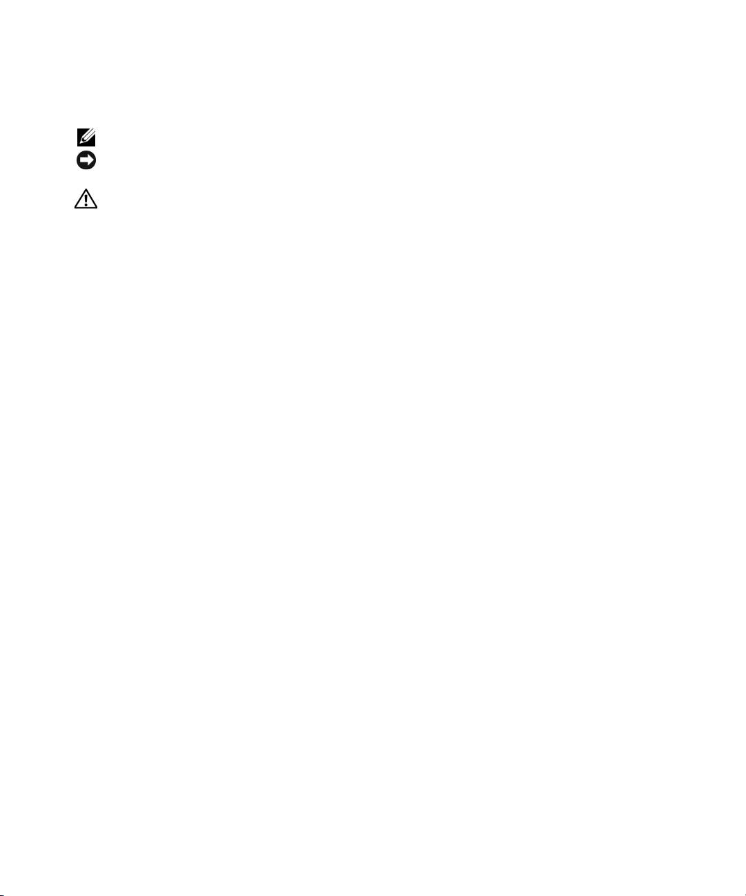
Unpack the System
Unpack your system and identify each item.
Keep all shipping materials in case you need them later.
6 Getting Started With Your System
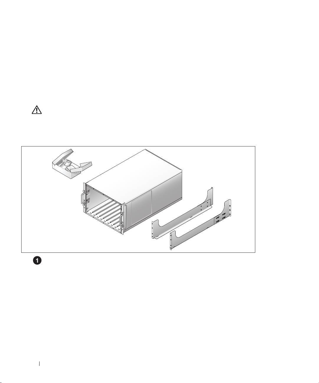
Install the System in a Rack
Install the system in the rack once you have read the "Safety Instructions" located in the rack
installation documentation for your system.
See your rack installation documentation for instructions on installing your system in a rack.
Getting Started With Your System 7
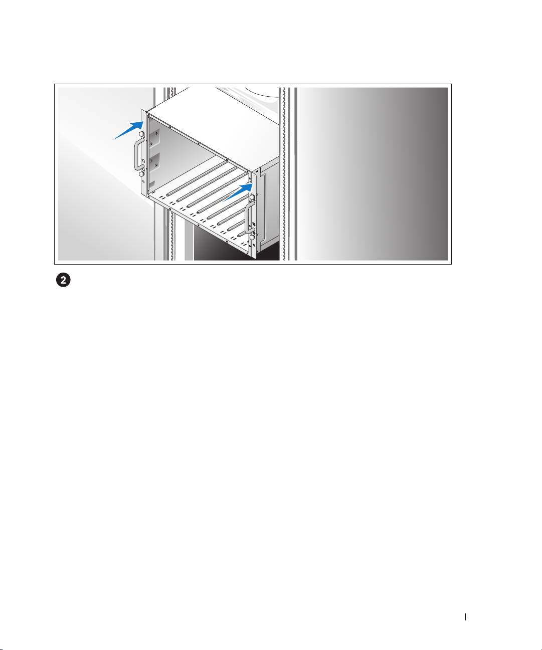
Install the Server Modules
Before installing the modules, orient each module so that the upper handle has the logo on it and
"TOP-SIDE" on the module edge faces upward. Press the release latch on the inside of the upper
handle. Pull out the upper and lower handles.
Beginning from left to right, slide the modules into the chassis. When the open handles contact the
chassis front panel, begin to rotate the handles together (the lower handle will close first) until the
lower handle is flush against the module’s front panel. Continue to rotate the upper handle downward
until it is flush against the lower handle. (When the handles are fully closed, the release latch will
secure both handles to the front panel.)
8 Getting Started With Your System
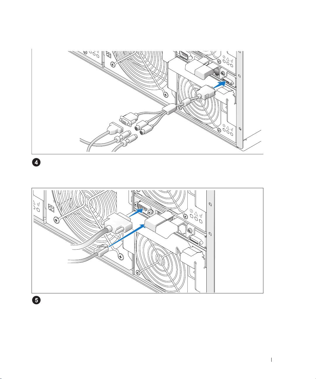
Connect the Keyboard, Mouse, and Monitor
Attach the custom cable to the KVM module, then connect the keyboard, mouse, and monitor
(optional) to the custom cable.
Connect the Management System
Connect the serial cable and network cable from the management system to the DRAC/MC module.
Getting Started With Your System 9
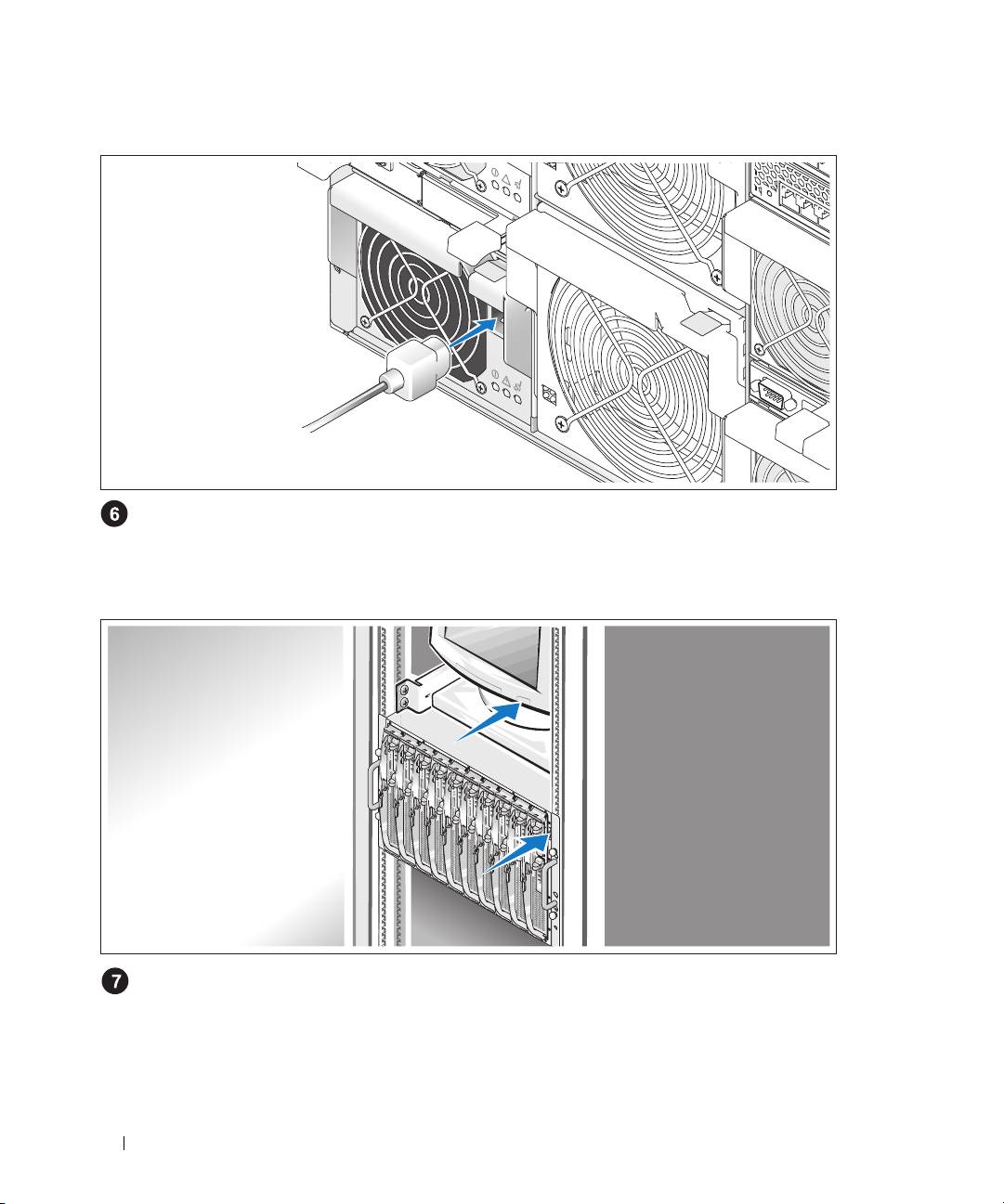
Connect the System and Monitor (Optional) to Power
Connect the system’s power cable(s) to the system. Next, plug the other end of the cable into a
grounded electrical outlet or a separate power source such as an uninterruptible power supply (UPS) or
a power distribution unit (PDU). Connect the monitor’s power cable to a grounded electrical outlet.
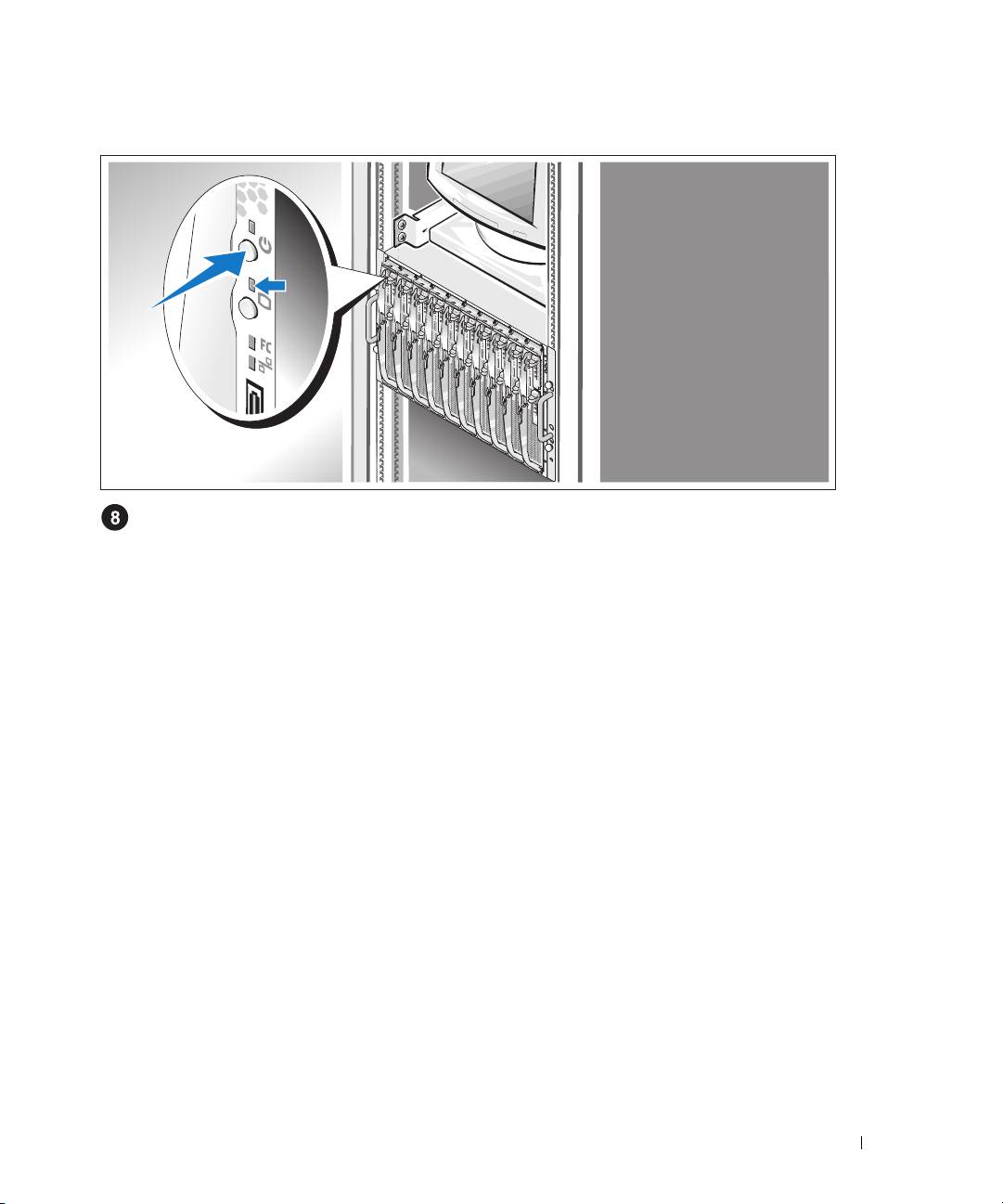
Turn on the System and Monitor (Optional)
Press the power button on the chassis and the monitor. The power indicators should light.
Adjust the monitor’s controls until the displayed image is satisfactory.
10 Getting Started With Your System
Turn on the Server Modules
Press the power button on each server module, or power on the modules using the systems
management software.
The KVM indicators on the server modules identify which server module video is displayed.
Adjust the monitor’s controls until the displayed image is satisfactory.
Complete the 0perating System Setup
If you purchased a preinstalled operating system, see the operating system documentation that ships
with your system. To install an operating system for the first time, see the Quick Installation Guide.
Be sure the operating system is installed before installing hardware or software not purchased with
the system.
Getting Started With Your System 11

Technical Specifications
Server Module
Processor
Processor type Up to two Intel Xeon Processor 5000 Sequence
Memory
Architecture FBD DDR II DIMMs, with two-way interleaving,
rated for 533- or 677-MHz (when available)
operation
Memory module sockets Eight 240-pin
Memory module capacities 256 MB, 512 MB, 1 GB, 2 GB, or 4 GB
Minimum RAM 512 MB
Maximum RAM
32 GB
Drives
Hard Drives
SAS configuration One or two 2.5-inch hot-pluggable hard drives
SATA configuration One or two 2.5-inch hot-pluggable hard drives
NOTE: SAS and SATA hard drives cannot be mixed
within a server module.
Connectors
Externally accessible
Front
Custom Supports two USB devices and video via custom
cable
Video
Video type ATI ES1000 video controller
Video memory 16 MB
12 Getting Started With Your System

Physical
Height 28.575 cm (11.25 in)
Width 4.241 cm (1.67 in)
Depth 50.8 cm (20 in)
Weight (maximum configuration) 7.257 kg (16 lb)
Battery
Server module battery
CR 2032 3.0-V lithium ion coin cell
System
System Enclosure
Height 31.038 cm (12.22 in)
Width 42.519 cm (16.74 in)
Depth 76.2 cm (30 in)
Weight (maximum configuration) 129.274 kg (285 lb)
Power Supply Module
AC power supply (per power supply)
Wattage 2100 W
Voltage 170–264 VAC, 50/60 Hz, 15.8 A at 170 VAC,
9.9 A at 264 VAC
Heat dissipation
3480
BTU/hr. maximum
Maximum inrush current Under typical line conditions and over the entire
system ambient operating range, the inrush current
may reach 55 A per power supply for 10 ms or less.
Physical
Height 9.70 cm (3.82 in)
Width 12.90 cm (5.08 in)
Depth 23.01cm (9.06 in)
Weight 3.288 kg (7.25 lb)
Getting Started With Your System 13

Fan Module
Physical
Height 14.732 cm (5.8 in)
Width 15.748 cm (6.2 in)
Depth 27.305 cm (10.75 in)
Weight 2.948 kg (6.5 lb)
KVM Module
Externally accessible connectors
Custom
Custom cable used for two PS/2 and one video
ACI port RJ-45
(Avocent Analog KVM switch only)
Ethernet RJ-45
(Avocent Digital Access KVM switch only)
Physical
Height
2.54 cm (1 in)
Width
5.334 cm (2.1 in)
Depth
28.194 cm (11.1 in)
Weight
0.272 kg (.6 lb)
DRAC/MC Module
Externally accessible connectors
Remote management Dedicated 10/100 RJ-45 (for integrated Ethernet
remote access controller)
Serial 9-pin, DTE, 16550-compatible
Battery
Module battery CR 2032 3.0-V lithium ion coin cell
Physical
Height
2.54 cm (1 in)
Width
7.493 cm (2.95 in)
Depth
26.03 cm (10.35 in)
Weight
0.363 kg (.8 lb)
14 Getting Started With Your System

PowerConnect 5316M Ethernet Switch Module
Externally accessible connectors
Gb 10/100/1000 Mbps Ethernet Six autonegotiating RJ-45 uplinks
Physical
Height 3.302 cm (1.3 in)
Width 13.081 cm (5.15 in)
Depth 27.432 cm (10.8 in)
Weight 0.816 kg (1.8 lb)
Gb Ethernet Pass-Through Module
Externally accessible connectors
Ethernet Ten RJ-45 uplinks (for integrated 1-Gbps NICs)
NOTE: Pass-through uplinks support 1000 Mbps
connection only.
Physical
Height
3.302 cm (1.3 in)
Width
13.081 cm (5.15 in)
Depth
27.432 cm (10.8 in)
Weight
0.816 kg (1.8 lb)
Fibre Channel Pass-Through Module
Externally accessible connectors
Fibre Channel transceiver
Ten 76-pin, 3.5 Gbps, GPI0 transceiver
receptacles
Physical
Height
3.302 cm (1.3 in)
Width
13.081 cm (5.15 in)
Depth
27.432 cm (10.8 in)
Weight
0.816 kg (1.8 lb)
Getting Started With Your System 15

Fibre Channel Switch Module
Externally accessible connectors
Fibre Channel
Four universal (E, F, and FL) autosensing ports
1/2/4 Gb/s Ethernet RJ-45
Physical
Height
3.302 cm (1.3 in)
Width
13.081 cm (5.15 in)
Depth
27.432 cm (10.8 in)
Weight
1.06 kg (2.35 lb)
Infiniband Pass-Through Module
Externally accessible connectors
Infiniband
Ten 4X ports
Physical
Height
3.302 cm (1.3 in)
Width
13.081 cm (5.15 in)
Depth
27.432 cm (10.8 in)
Weight
1.8 kg (4 lb)
16 Getting Started With Your System

Environmental
NOTE: For additional information about environmental measurements for specific system configurations,
see www.dell.com/environmental_datasheets. The system is not for use in an office environment.
Tempe rature
Operating 10° to 35°C (50° to 95°F)
NOTE: Decrease the maximum temperature by 1°C
(1.8°F) per 300 m (985 ft) above 900 m (2955 ft).
Storage –40° to 65°C (–40° to 149°F)
Relative humidity
Operating 8% to 85% (noncondensing) with a maximum
humidity gradation of 10% per hour
Storage 5% to 95% (noncondensing)
Maximum vibration
Operating 0.25 G at 3–200 Hz for 15 min
Storage 0.5 G at 3–200 Hz for 15 min
Maximum shock
Operating One shock pulse in the positive z axis (one pulse on
each side of the system) of 41 G for up to 2 ms
Storage Six consecutively executed shock pulses in the
positive and negative x, y, and z axes (one pulse on
each side of the system) of 71 G for up to 2 ms
Altitude
Operating –16 to 3048 m (–50 to 10,000 ft)
Storage –16 to 10,600 m (–50 to 35,000 ft)
Getting Started With Your System 17

18 Getting Started With Your System
