Dell PowerEdge C5220: инструкция
Раздел: Компьютерные комплектующие
Тип:
Инструкция к Dell PowerEdge C5220
Оглавление
- Примечания, предупреждения и предостережения
- Установка и конфигурирование Распаковка системы
- Установка систем с неинструментальными направляющими 1
- 2 3
- Установка системы Удалите все из шасси системы 1 2
- 3 4 5 6
- Установка системы в стойку
- Установка компонентов системы 1 2
- 3
- 4 Подключение клавиатуры, мыши и монитора
- Подключение силовых кабелей Включение системы
- Завершение установки операционной системы Поддерживаемые операционные системы Прочая полезная информация
- Технические характеристики Процессор(на одну системную плату) Шина расширения(на одну системную плату) Память(на одну системную плату) Накопители (на одну системную плату) Разъемы (на одну системную плату)
- Видео Power (Питание) Физические характеристики
- Условия эксплуатации и хранения
- Условия эксплуатации и хранения (продолжение) Акустика

Dell PowerEdge C5220
Getting Started
With Your System
Začínáme se systémem
Guide de mise en route
Erste Schritte mit dem System
Τα πρώτα βήµατα µε το σύστηµά σας
Rozpoczęcie pracy z systemem
Начало работы с системой
Procedimientos iniciales con el sistema
Sisteminizi Kullanmaya Başlarken
תכרעמה םע הדובעה תליחת


Dell PowerEdge C5220
Getting Started
With Your System
Regulatory Model B04S
Notes, Cautions, and Warnings
NOTE: A NOTE indicates important information that helps you make better use
of your system.
CAUTION: A CAUTION indicates potential damage to hardware or loss of data
if instructions are not followed.
WARNING: A WARNING indicates a potential for property damage, personal
injury, or death.
____________________
Information in this publication is subject to change without notice.
© 2011 Dell Inc. All rights reserved.
Reproduction of these materials in any manner whatsoever without the written permission of Dell Inc.
is strictly forbidden.
Trademarks used in this text: Dell™, the DELL logo, and PowerEdge™ are trademarks of Dell Inc.
®
®
®
Intel
and Intel
Xeon
are registered trademarks of Intel Corporation in the U.S. and other countries.
®
®
Microsoft
and Windows
are either trademarks or registered trademarks of Microsoft Corporation
®
®
in the United States and/or other countries. Red Hat
and Red Hat Enterprise Linux
are registered
trademarks of Red Hat, Inc. in the United States and/or other countries. SUSE™ is a trademark of
®
®
®
Novell Inc. in the United States and other countries. Citrix
, Xen
, and XenServer
are either
registered trademarks or trademarks of Citrix Systems, Inc. in the United States and/or other countries.
®
VMware
is a registered trademarks or trademarks of VMWare, Inc. in the United States or other
countries.
Other trademarks and trade names may be used in this publication to refer to either the entities claiming
the marks and names or their products. Dell Inc. disclaims any proprietary interest in trademarks and
trade names other than its own.
Regulatory Model B04S
2011-04 P/N 505MT Rev. A00
CAUTION: Restricted Access Location
This server is intended for installation only in restricted access locations as
defined in Cl. 1.2.7.3 of IEC 60950-1: 2001 where both these conditions
apply:
• Access can only be gained by service persons or by users who have been
instructed about the reasons for the restrictions applied to the location and
about any precautions that shall be taken.
• Access is through the use of a tool or lock and key, or other means of
security, and is controlled by the authority responsible for the location.
Installation and Configuration
WARNING: Before performing the following procedure, review and follow the
safety instructions that came with the system.
Unpacking the System
Unpack your system and identify each item.
Installing the Tool-Less Rail Solution
WARNING: Whenever you need to lift the system, get others to assist you. To
avoid injury, do not attempt to lift the system by yourself.
WARNING: The system is not fixed to the rack or mounted on the rails. To avoid
personal injury or damage to the system, you must adequately support the system
during installation and removal.
WARNING: To avoid a potential electrical shock hazard, a third wire safety
grounding conductor is necessary for the rack installation. The rack equipment
must provide sufficient airflow to the system to maintain proper cooling.
CAUTION: When installing rails in a square-hole rack it is important to ensure
that the square peg slides through the square holes.
CAUTION: Square studs must be flush with the rack posts to install properly.
Installation and Configuration 3
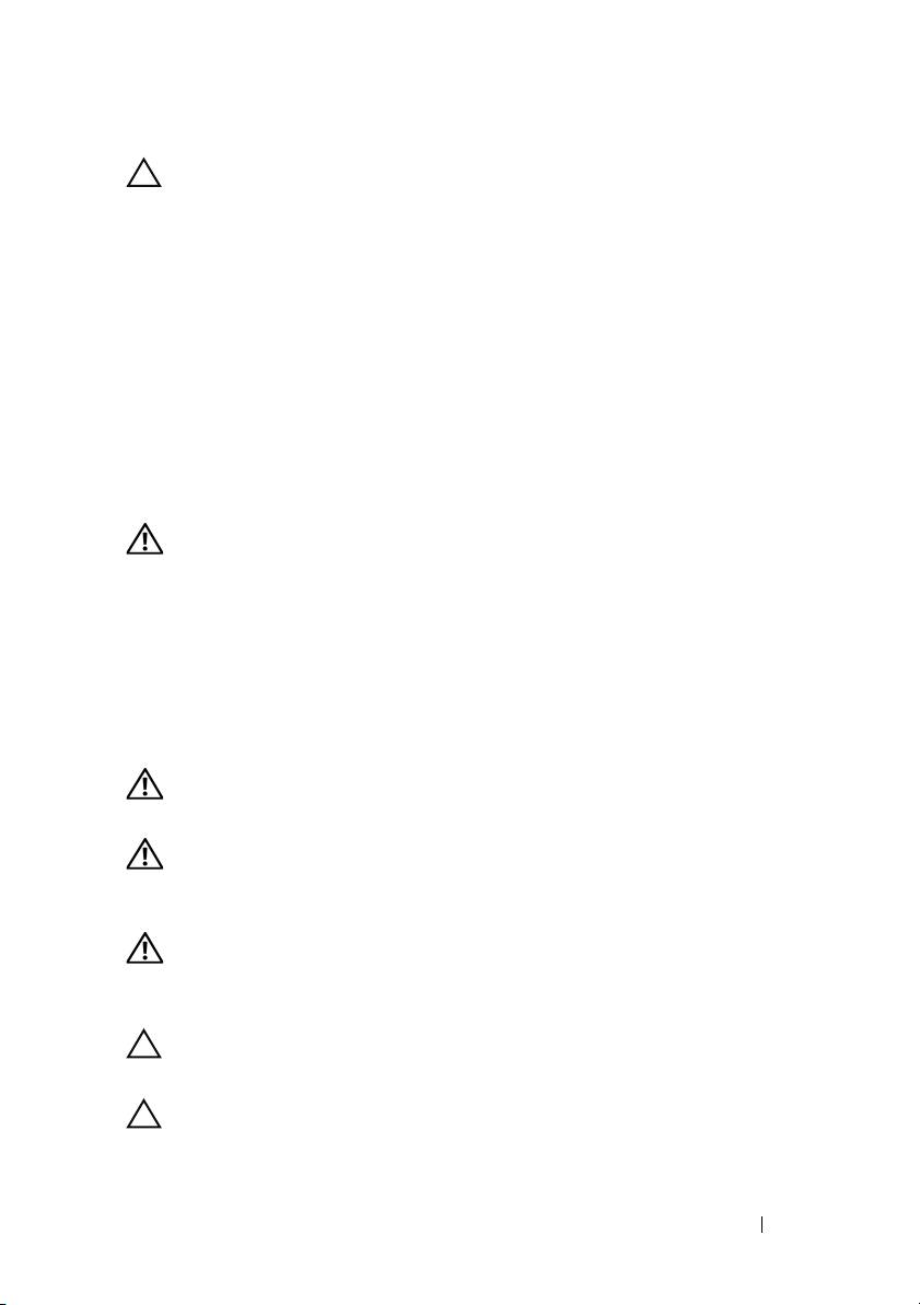
1
Pull on the latch release buttons on the end piece midpoints to open the
rail latches.
2
Align the end pieces of the rails on the vertical rack flanges to seat the pegs
in the bottom hole of the first U and the top hole of the second U. Engage
the back end of the rail until the latch locks in place.
NOTE: The rails can be used in both square-hole and round-hole racks.
Back
Front
3
Repeat steps 1 to 2 to position and seat the front end piece on the vertical
flange.
NOTE: To remove the rails, pull on the latch release button on the end piece
midpoint and unseat each rail.
4 Installation and Configuration
Installing the System
Empty the System Chassis
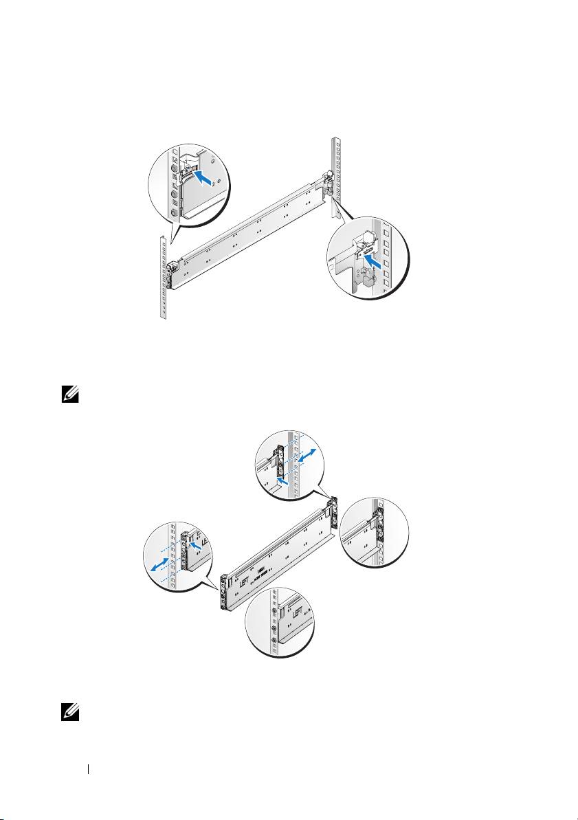
1
Unplug the power cable from the power supply unit.
.
2
Pull out the power supply unit handle.
Installation and Configuration 5
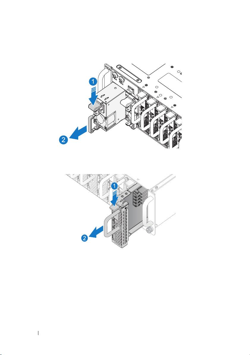
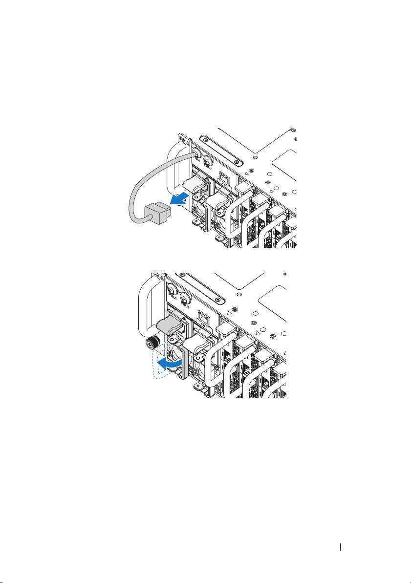
3
Press down on the release latch
.
4
Pull the power supply unit out of the system
.
5
Press the release latch down
.
6
Pull the sled out of the system
.
6 Installation and Configuration
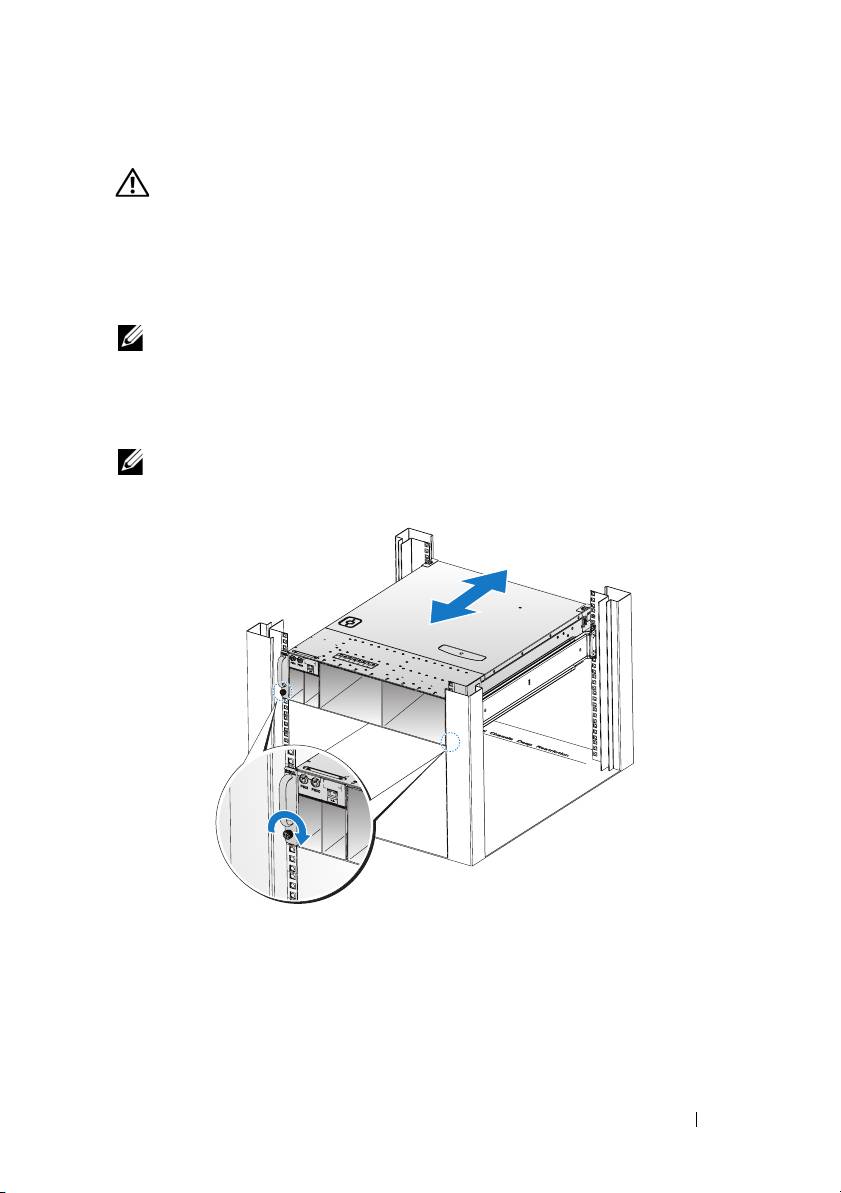
Installing the System Into the Rack
WARNING: Whenever you need to lift the system, get others to assist you.
To avoid injury, do not attempt to lift the system by yourself.
1
Slide the system into the rack.
2
If present, remove the chassis stabilizer shipping bracket (optional) from
the rack.
NOTE: To transport systems already installed in the rack, ensure that the two
chassis stabilizer shipping brackets (optional) are in place.
3
Tighten the captive thumbscrews to secure the ears of the system to the
front of the rack.
NOTE: Make sure the latch release mechanism is engaged correctly.
Installation and Configuration 7
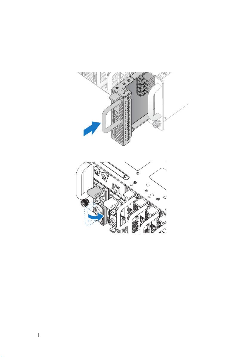
Populate the System
1
Push the power supply unit into the system until flush with the case and
the release latch locks.
2
Close the power supply unit handle.
8 Installation and Configuration
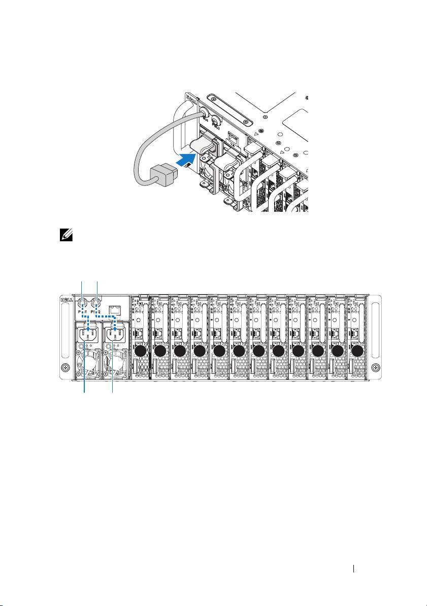
3
Plug the chassis power cable into the power supply unit.
NOTE: The correct configuration of the integral chassis AC power cables to the
PSU sockets is as shown in the following illustration.
PSU1 PSU2
1 2 3 4 5 6 7 8 9 10 11 12
PSU1 PSU2
Installation and Configuration 9
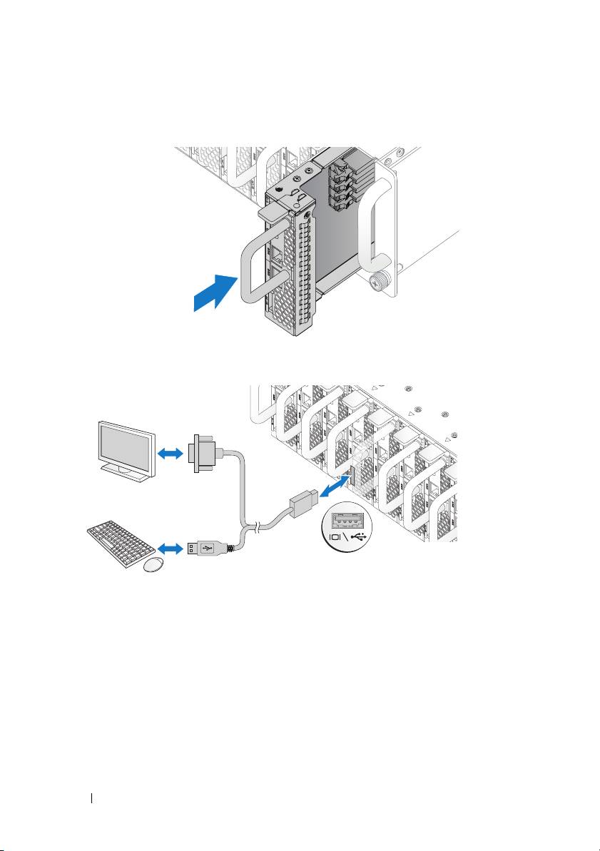
4
Push the sled into the system until flush with the case and the release latch
locks.
Connecting the Keyboard, Mouse, and Monitor
The connector on the front of your system has an icon indicating which cable
to plug in. Connect a keyboard, mouse, or monitor (optional).
10 Installation and Configuration
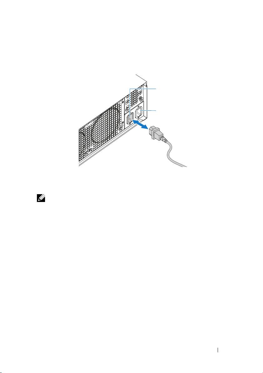
Connecting the Power Cables
1
On the back of the system, connect the mains power cable to the system’s
power socket.
AC Port 2
AC Port 1
2
Plug the other end of the power cables into a grounded electrical outlet or
a separate power source such as an uninterrupted power supply or a power
distribution unit.
NOTE:
AC Port 1 provides power to PSU1, AC Port 2 provides power to PSU2.
For more information, see step 3 of Populate the System.
Turning On the System
When connected to a power source the system automatically powers on.
See Using the Baseboard Management Controller Guide at
support.dell.com/manuals.
Installation and Configuration 11
Complete the Operating System Setup
To install an operating system for the first time, see the installation and
configuration documentation for your operating system. Be sure the
operating system is installed before installing hardware or software not
purchased with the system.
Supported Operating Systems
• Microsoft Windows Server 2008 R2 Enterprise
• Microsoft HPC Server 2008 R2
• Microsoft Windows Server 2008 R2 Hyper-V
• Red Hat Enterprise Linux 6.0 (64-bit)
• Red Hat Enterprise 5 Update 5 (64-bit)
• SUSE Linux Enterprise Server 11 Service Pack 1 (64-bit)
• VMware ESX 4.1 Update 1
• VMware ESXi 4.1 Update 1 (Embedded option for SDHC)
• Citrix XenServer 5.6 Feature Pack 1
NOTE:
For the latest information on supported operating systems, see
support.dell.com.
Other Information You May Need
WARNING: See the safety and regulatory information that shipped with your
system. Warranty information may be included within this document or as a
separate document.
See the Hardware Owner’s Manual at support.dell.com/manuals for
information about system features, troubleshooting, and component
replacement.
See Using the Baseboard Management Controller Guide at
support.dell.com/manuals.
NOTE: Always check for updates on support.dell.com/manuals and read the
updates first because they often supersede information in other documents.
12 Installation and Configuration

Technical Specifications
Processor (Per System Board)
Processor type Intel Xeon Processor E3-1200 product
family
Expansion Bus (Per System Board)
Bus type PCI-E x8 Gen 2
Expansion slots Mezzanine connector
Memory (Per System Board)
Architecture Dual Channel Unbuffered DDR3
1066/1333
Memory module sockets 4
Memory module capacities
Minimum RAM 2 GB
Maximum RAM 32 GB
Drives (Per System Board)
2.5" hard drives SAS 6 Gb (4 channels)
SATA 3 Gb (4 channels)
3.5" hard drives SAS 6 Gb (2 channels)
SATA 3 Gb (2 channels)
Connectors (Per System Board)
Front
NIC 10/100/1G (RJ45)
2
USB 2.0 (through Y-cable)
2
Video (DB15) (through Y-cable)
1
Video
Video type AST2050
Video memory 8 MB DDR2 SDRAM
Technical Specifications 13

Power
AC power supply (per power supply)
Wa tt ag e
1400 W
Voltage
200-240 VAC, 50/60 Hz
Heat dissipation
55.67 BTU/hr max
Maximum inrush current
55 A max
Physical
Height 13 cm (5.1 in)
Width 44.7 cm (17.6 in)
Depth 75 cm (29.5 in)
Weight (loaded: maximum weight) 8-sled configuration:
42.4 kg (93.48 lbs.)
12-sled configuration:
48.13 kg (106.11 lbs.)
Weight (empty) 8-sled configuration:
27.4 kg (60.41 lbs.)
12-sled configuration:
32.02 kg (70.59 lbs.)
Environmental
NOTE: For additional information about environmental measurements for specific
system configurations, see dell.com/environmental_datasheets.
Temperature
Operating
10°C to 35°C (50°F to 95°F) with a
maximum temperature gradation of 10°C
(per hour)
NOTE: For altitudes above 2,950 feet, the
maximum operating temperatures derated
to 1°F/550 ft.
Storage
–40°C to 65°C (-40°F to 149°F) with a
maximum temperature gradation of 20°C
per hour
14 Technical Specifications

Environmental (continued)
Relative Humidity
Operating
20% to 80% (noncondensing) with a
maximum humidity gradation of 10%
per hour
Storage
5% to 95% (noncondensing)
Maximum vibration
Operating
0.26 Grms at 5–350 Hz
Storage
1.87 Grms at 10–500 Hz for 15 minutes
Maximum shock
Operating
One shock pulse in the positive z axis
(one pulse on each side of the system) of
31 G for 2.6 ms in the operational
orientation
Storage
Six consecutively executed shock pulses
in the positive and negative x, y, and z
axes (one pulse on each side of the
system) of 71 G for up to 2 ms.
Six consecutively executed shock pulses
in the positive and negative x, y, and z
axes (one pulse on each side of the
system) of 22 G faired square wave pulse
with velocity change at 200 inches/second
Altitude
Operating
-16 to 3,048 m (-50 to 10,000 ft.)
Storage
-16 to 10,600 m (-50 to 35,000 ft.)
Airborne Contaminant Level
Class
G1 as defined by ISA-S71.04-1985
Technical Specifications 15

Acoustics
Sound Power (Units: LwAd-UL,bels)
Idle in 23 ± 2
°
C ambient
<= 7.0
SPEC power at 50% in 23 ± 2
°
C
<= 7.2
ambient
NOTE: LwAd-UL is the upper limit sound power level (LwAd) calculated by ISO 9296
(1988) and measured in accordance with ISO7779 (1999).
16 Technical Specifications

Dell PowerEdge C5220
Začínáme
se systémem
Regulatorní model B04S

Poznámky a upozornění
POZNÁMKA: POZNÁMKA označuje důležité informace, které pomáhají
lepšímu využití systému.
UPOZORNĚNÍ: UPOZORNĚNÍ označuje nebezpečí poškození
hardwaru nebo ztráty dat v případě nedodržení pokynů.
VAROVÁNÍ: VAROVÁNÍ upozorňuje na potenciální nebezpečí
poškození majetku, úrazu nebo smrti.
____________________
Informace v této publikaci se mohou bez předchozího upozornění změnit.
© 2011 Dell Inc. Všechna práva vyhrazena.
Jakákoli reprodukce těchto materiálů bez písemného povolení společnosti Dell Inc. je přísně zakázána.
Ochranné známky použité v tomto textu: Dell™, logo DELL a PowerEdge™ jsou ochranné známky
®
®
®
společnosti Dell Inc. Intel
a Intel
Xeon
jsou registrované ochranné známky společnosti Intel
®
®
Corporation v USA a dalších zemích. Microsoft
a Windows
jsou ochranné známky nebo
®
registrované ochranné známky společnosti Microsoft Corporation v USA a dalších zemích. Red Hat
®
a Red Hat Enterprise Linux
jsou registrované ochranné známky společnosti Red Hat, Inc. v USA a
®
dalších zemích. SUSE™ je ochranná známka společnosti Novell Inc. v USA a dalších zemích. Citrix
,
®
®
Xen
a XenServer
jsou registrované ochranné známky nebo ochranné známky společnosti Citrix
®
Systems, Inc. v USA a dalších zemích. VMware
je registrovaná ochranná známka společnosti
VMware, Inc. v USA a dalších zemích.
V této publikaci mohou být použity další ochranné známky a obchodní názvy s odkazem na společnosti
vlastnící tyto známky a názvy nebo na jejich produkty. Společnost Dell Inc. nemá vlastnické zájmy
vůči ochranným známkám a obchodním názvům jiným než svým vlastním.
Regulatorní model B04S
Duben 2011 Č. dílu 505MT Rev. A00
