Dell Precision 490: инструкция
Раздел: Бытовая, кухонная техника, электроника и оборудование
Тип: Компьютер
Инструкция к Компьютеру Dell Precision 490
Оглавление
- Примечания, предупреждения и важная информация Сокращения и акронимы
- Содержание
- Поиск информации Возможные направления поиска Где искать
- Возможные направления поиска Где искать
- Возможные направления поиска Где искать
- Возможные направления поиска Где искать
- Установка компьютера (вертикальное положение корпуса) 1 2
- 3
- Видеоплата для подключения одного и двух мониторов, с одним разъемом VGA-адаптер с дуальным Y-кабелем DVI-адаптер с дуальным Y-кабелем
- Видеоплата для подключения двух мониторов, с одним DVI- и одним VGA-разъемом Видеоплата для подключения двух мониторов, с двумя DVI-разъемами
- 4 5
- 6 Установка компьютера (горизонтальное положение корпуса) 1
- 2 3
- Видеоплата для подключения одного и двух мониторов, с одним разъемом VGA-адаптер с дуальным Y-кабелем DVI-адаптер с дуальным Y-кабелем
- Видеоплата для подключения двух мониторов, с одним DVI- и одним VGA-разъемом Один DVI- и один VGA-разъем Два VGA-разъема с одним VGA-адаптером Видеоплата для подключения двух мониторов, с двумя DVI-разъемами
- 4 5 6
- О компьютере Вид спереди (вертикальное положение корпуса)
- 13 индикаторы диагностики (4)
- Вид сзади (вертикальное положение корпуса)
- Разъемы задней панели
- 11 разъем последовательного порта
- Вид спереди (горизонтальное положение корпуса) 7 Вращаемый значок Dell™
- 13 Индикаторы диагностики (4)
- Вид сзади (горизонтальное положение корпуса)
- Вид изнутри
- Вид изнутри — повернутый отсек для жесткого диска
- Элементы системной платы
- Цвета кабелей
- Дополнительная информация, содержащаяся в руководстве пользователя Снятие крышки корпуса компьютера 1 2
- 3 4 5 6 7
- Уход за компьютером Решение проблем Советы по устранению неполадок Несовместимость программного и аппаратного обеспечения
- Восстановление системы в Microsoft Создание точки восстановления Восстановление более раннего работоспособного состояния компьютера
- Отмена последнего восстановления системы Включение функции System Restore Использование последней работоспособной конфигурации
- Другие возможности решения конфликтов аппаратного и программного обеспечения Программа Dell Diagnostics Когда использовать программу Dell Diagnostics
- Запуск программы Dell Diagnostics с жесткого диска Запуск программы Dell Diagnostics с компакт-диска Drivers and Utilities
- Перед началом тестирования Звуковые коды Код Причина
- Код Причина Сообщения об ошибках
- Индикаторы диагностики Коды индикаторов диагностики перед выполнением теста POST Индикаторы диагностики
- Индикаторы диагностики
- Индикаторы диагностики Сигналы диагностических светодиодов во время процедуры POST Светодиоды Описание проблемы Варианты решения
- Светодиоды Описание проблемы Варианты решения
- Светодиоды Описание проблемы Варианты решения
- Часто задаваемые вопросы Как сделать... Решение Источник информации
- Как сделать... Решение Источник информации
- Индекс
- 286 Индекс
- Индекс 287

Dell Precision™ Workstation 490
Quick Reference Guide
Model DCTA
www.dell.com | support.dell.com

Notes, Notices, and Cautions
NOTE: A NOTE indicates important information that helps you make better use of your computer.
NOTICE: A NOTICE indicates either potential damage to hardware or loss of data and tells you how to avoid
the problem.
CAUTION: A CAUTION indicates a potential for property damage, personal injury, or death.
Abbreviations and Acronyms
For a complete list of abbreviations and acronyms, see the Glossary in your
User’s Guide
.
®
®
If you purchased a Dell™ n Series computer, any references in this document to Microsoft
Windows
operating systems are not applicable.
____________________
Information in this document is subject to change without notice.
© 2006 Dell Inc. All rights reserved.
Reproduction in any manner whatsoever without the written permission of Dell Inc. is strictly forbidden.
Trademarks used in this text: Dell, the DELL logo and Dell Precision are trademarks of Dell Inc.; Intel, Xeon, and Pentium are registered
trademarks of Intel Corporation; Microsoft and Windows are registered trademarks of Microsoft Corporation.
Other trademarks and trade names may be used in this document to refer to either the entities claiming the marks and names or their products.
Dell Inc. disclaims any proprietary interest in trademarks and trade names other than its own.
Model DCTA
January 2006 P/N MD504 Rev. A00

Contents
Finding Information . . . . . . . . . . . . . . . . . . . . . . . . . . . . . . . . 5
Setting Up Your Computer (Tower Orientation)
. . . . . . . . . . . . . . . . . . 9
Setting Up Your Computer (Desktop Orientation)
. . . . . . . . . . . . . . . . 14
About Your Computer
. . . . . . . . . . . . . . . . . . . . . . . . . . . . . . . 19
Front View (Tower Orientation)
. . . . . . . . . . . . . . . . . . . . . . . 19
Back View (Tower Orientation)
. . . . . . . . . . . . . . . . . . . . . . . 21
Back Panel Connectors
. . . . . . . . . . . . . . . . . . . . . . . . . . . 22
Front View (Desktop Orientation)
. . . . . . . . . . . . . . . . . . . . . . 24
Back View (Desktop Orientation)
. . . . . . . . . . . . . . . . . . . . . . 25
Inside View
. . . . . . . . . . . . . . . . . . . . . . . . . . . . . . . . . 26
Inside View – Hard Drive Bay Rotated Out
. . . . . . . . . . . . . . . . . 27
System Board Components
. . . . . . . . . . . . . . . . . . . . . . . . . 28
Cable Colors
. . . . . . . . . . . . . . . . . . . . . . . . . . . . . . . . . 29
Locating Your User’s Guide
. . . . . . . . . . . . . . . . . . . . . . . . . . . 29
Removing the Computer Cover
. . . . . . . . . . . . . . . . . . . . . . . . . . 30
Caring for Your Computer
. . . . . . . . . . . . . . . . . . . . . . . . . . . . 32
Solving Problems
. . . . . . . . . . . . . . . . . . . . . . . . . . . . . . . . 32
Troubleshooting Tips
. . . . . . . . . . . . . . . . . . . . . . . . . . . . 32
Resolving Software and Hardware Incompatibilities
. . . . . . . . . . . 32
®
®
Using Microsoft
Windows
XP System Restore . . . . . . . . . . . . . 33
Using the Last Known Good Configuration
. . . . . . . . . . . . . . . . . 34
Dell Diagnostics
. . . . . . . . . . . . . . . . . . . . . . . . . . . . . . . 35
Before You Start Testing
. . . . . . . . . . . . . . . . . . . . . . . . . . 36
Beep Codes
. . . . . . . . . . . . . . . . . . . . . . . . . . . . . . . . . . . . 36
Error Messages
. . . . . . . . . . . . . . . . . . . . . . . . . . . . . . . 38
Diagnostic Lights
. . . . . . . . . . . . . . . . . . . . . . . . . . . . . . . . . 38
Diagnostic Light Codes Before POST
. . . . . . . . . . . . . . . . . . . . 38
Diagnostic Light Codes During POST
. . . . . . . . . . . . . . . . . . . . 40
Frequently Asked Questions
. . . . . . . . . . . . . . . . . . . . . . . . . . . 43
Index . . . . . . . . . . . . . . . . . . . . . . . . . . . . . . . . . . . . . . . . . 45
Contents 3

4 Contents
Finding Information
NOTE: Some features or media may be optional and may not ship with your computer. Some features or media may
not be available in certain countries.
NOTE: Additional information may ship with your computer.
What Are You Looking For? Find It Here
• A diagnostic program for my computer
Drivers and Utilities CD (also known as Resource CD)
• Drivers for my computer
Documentation and
• My computer documentation
drivers are already
• My device documentation
installed on your
computer. You can use
• Desktop System Software (DSS)
the CD to reinstall drivers,
run the Dell Diagnostics,
or access your
documentation. Readme
files may be included on
your CD to provide last-
minute updates about
technical changes to your computer or advanced technical-
reference material for technicians or experienced users.
NOTE: Drivers and documentation updates can be found
at support.dell.com.
• How to set up my computer
Quick Reference Guide
• How to care for my computer
• Basic troubleshooting information
• How to run the Dell Diagnostics
• Error codes and diagnostic lights
• How to remove and install parts
• How to open my computer cover
NOTE: This document is available as a PDF at
support.dell.com.
Quick Reference Guide 5
What Are You Looking For? Find It Here
• Warranty information
Dell™ Product Information Guide
• Terms and Conditions (U.S. only)
• Safety instructions
• Regulatory information
• Ergonomics information
• End User License Agreement
• How to remove and replace parts
User’s Guide
• Specifications
®
®
Microsoft
Windows
XP Help and Support Center
• How to configure system settings
1
Click the Start button and click
Help and Support
• How to troubleshoot and solve problems
2
Click User’s and system guides and click
User’s Guide
The User’s Guide is also available on the Drivers and
Utilities CD.
®
®
• Service Tag and Express Service Code
Service Tag and Microsoft
Windows
License
• Microsoft Windows License Label
These labels are located on your computer.
• Use the Service Tag to
identify your computer
when you use
support.dell.com
or
contact technical
support.
• Enter the Express
Service Code to direct your call when contacting
technical support.
6 Quick Reference Guide

What Are You Looking For? Find It Here
• Solutions — Troubleshooting hints and tips, articles
Dell Support Website — support.dell.com
from technicians, and online courses, frequently
NOTE: Select your region or business segment to view the
asked questions
appropriate support site.
• Community — Online discussion with other
NOTE: Corporate, government, and education customers
Dell customers
can also use the customized Dell Premier support website at
• Upgrades — Upgrade information for components,
premier.support.dell.com. The website may not be available
such as memory, the hard drive, and the
in all regions.
operating system
• Customer Care — Contact information, service call
and order status, warranty, and repair information
• Service and support — Service call status and
support history, service contract, online discussions
with technical support
• Reference — Computer documentation, details on
my computer configuration, product specifications,
and white papers
• Downloads — Certified drivers, patches, and
software updates
• Desktop System Software (DSS)— If you reinstall
the operating system for your computer, you should
reinstall the DSS utility prior to installing any of the
drivers. DSS provides critical updates for your
operating system and support for Dell™ 3.5-inch
USB floppy drives, optical drives, and USB devices.
DSS is necessary for correct operation of your Dell
computer. The software automatically detects your
computer and operating system and installs the
updates appropriate for your configuration.
• How to use Windows XP
Windows Help and Support Center
• How to work with programs and files
1
Click the
Start
button and click
Help and Support
.
• Documentation for devices (such as modem)
2
Type a word or phrase that describes your problem
and click the arrow icon.
3
Click the topic that describes your problem.
4
Follow the instructions on the screen.
Quick Reference Guide 7

What Are You Looking For? Find It Here
• How to reinstall my operating system
Operating System CD
The operating system is
already installed on your
computer. To reinstall
your operating system, use
the Operating System CD.
See your User’s Guide for
instructions. After you
reinstall your operating
system, use the Drivers and
Utilities CD (Resource CD)
to reinstall drivers for the
devices that came with your computer. Your operating
system product key label is located on your computer.
NOTE: The color of your CD varies based on the operating
system you ordered.
NOTE: The Operating System CD may be optional and may
not ship with your computer.
• How to use Linux
Dell Supported Linux Sites
• E-mail discussions with users of Dell Precision™
• Linux.dell.com
products and the Linux operating system
• Lists.us.dell.com/mailman/listinfo/linux-precision
• Additional information regarding Linux
and my Dell Precision computer
8 Quick Reference Guide
Setting Up Your Computer (Tower Orientation)
CAUTION: Before you begin any of the procedures in this section, follow the safety instructions
in the Product Information Guide.
You must complete all steps to properly set up your computer.
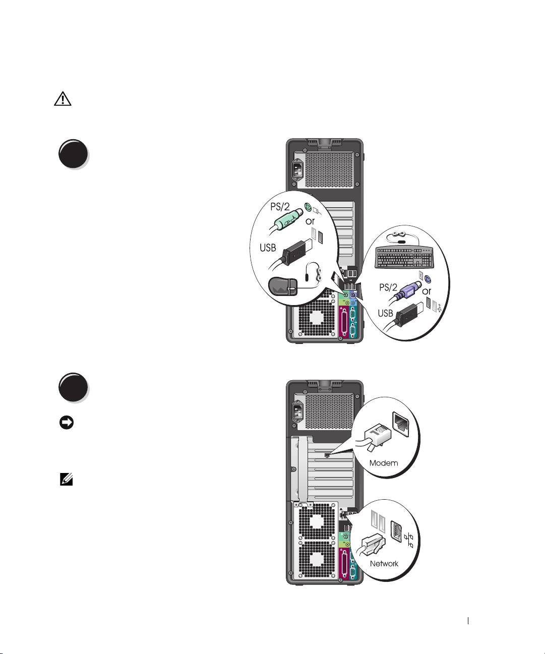
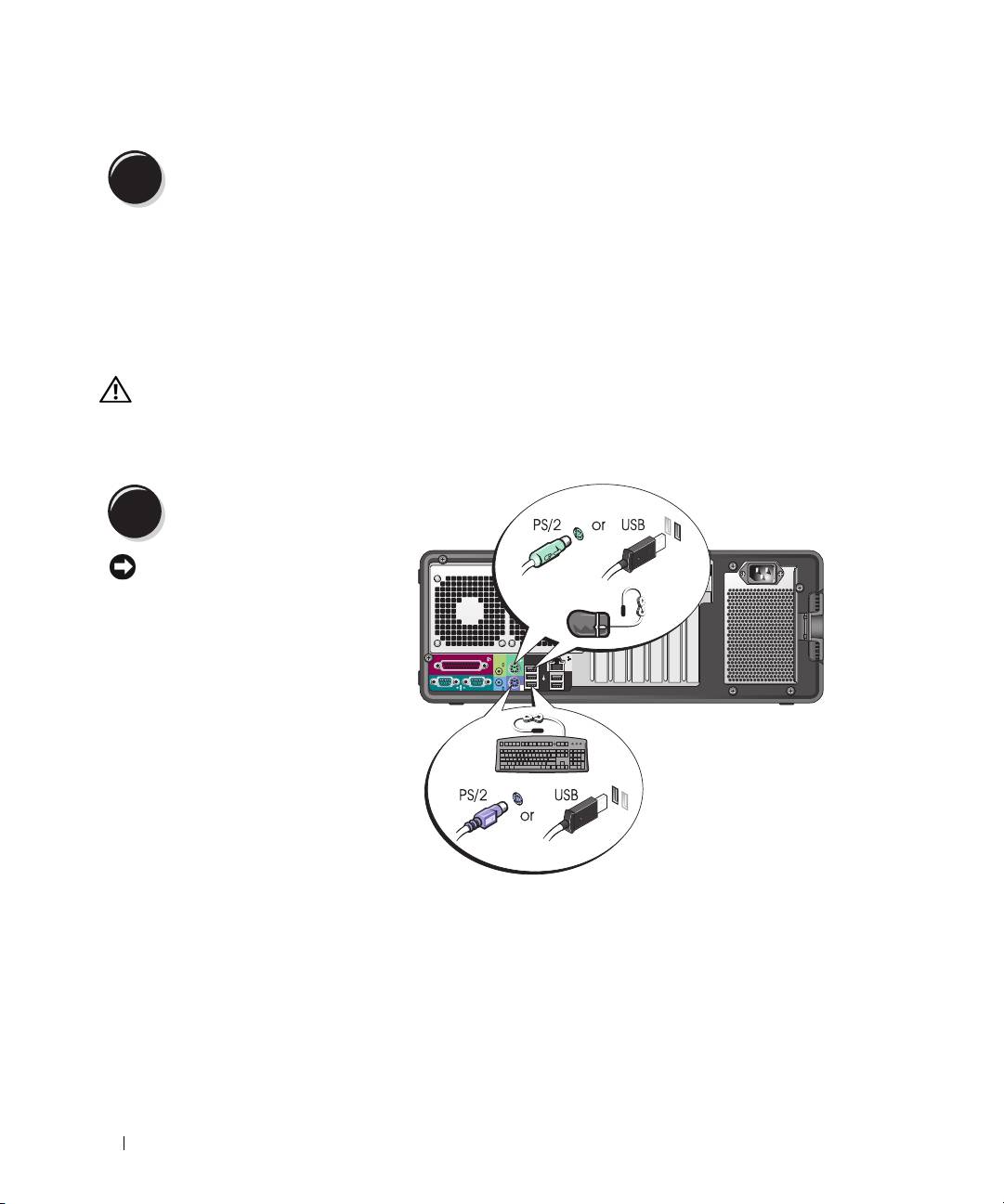
Connect the keyboard and the mouse.
1
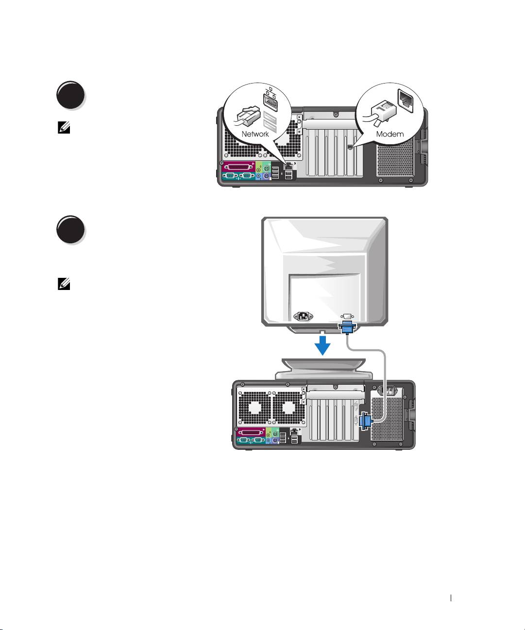
Connect the modem or the network cable.
2
NOTICE: Do not connect a modem cable to the
network adapter. Voltage from telephone
communications can damage the network adapter.
NOTE: If your computer has a network card installed,
connect the network cable to the card.
Quick Reference Guide 9
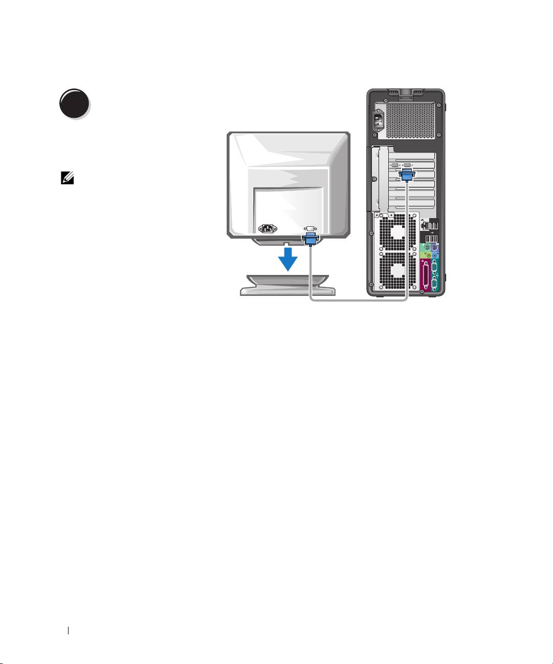
Connect the monitor.
3
Depending on your graphics
card, you can connect your
monitor in various ways.
NOTE: You may need to use
the provided adapter or
cable to connect your
monitor to the computer.
10 Quick Reference Guide
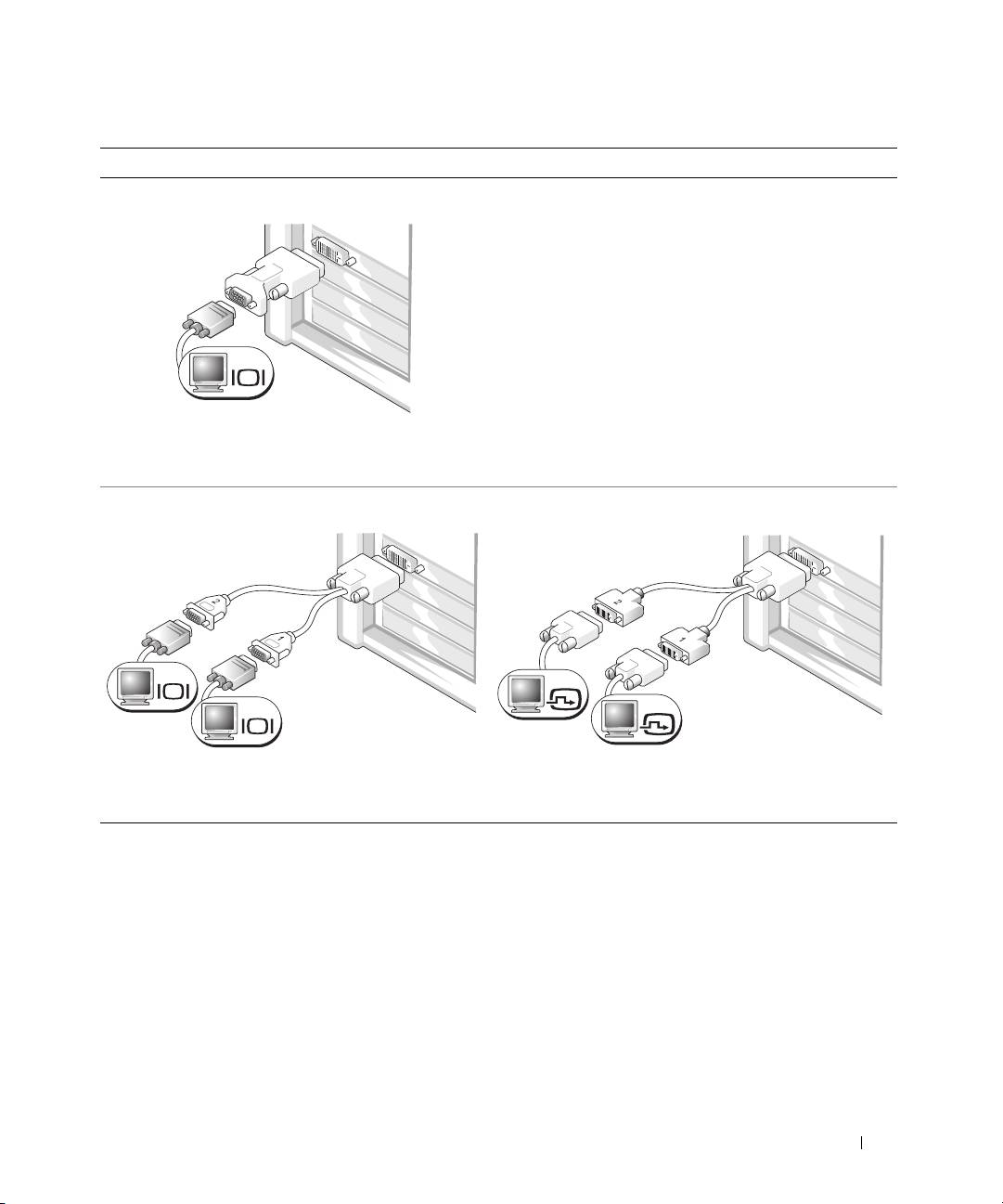
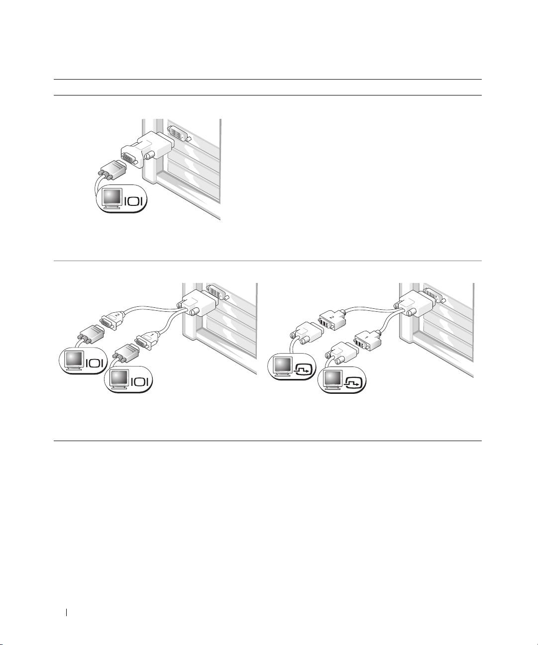
For single- and dual-monitor capable cards with a single connector
One VGA adapter:
VGA
Use the VGA adapter when you have a single-monitor
graphics card and you want to connect your computer
to a VGA monitor.
Dual VGA Y cable adapter:
Dual DVI Y cable adapter:
VGA
DVI
DVI
VGA
Use the appropriate Y cable when your graphics card
Use the appropriate Y cable when your graphics card has a
has a single connector and you want to connect your
single connector and you want to connect your computer
computer to one or two VGA monitors.
to one or two DVI monitors.
The dual-monitor cable is color-coded; the blue connector is for the primary monitor, and the black
connector is for the second monitor. To enable dual-monitor support, both monitors must be attached
to the computer when you start the computer.
Quick Reference Guide 11
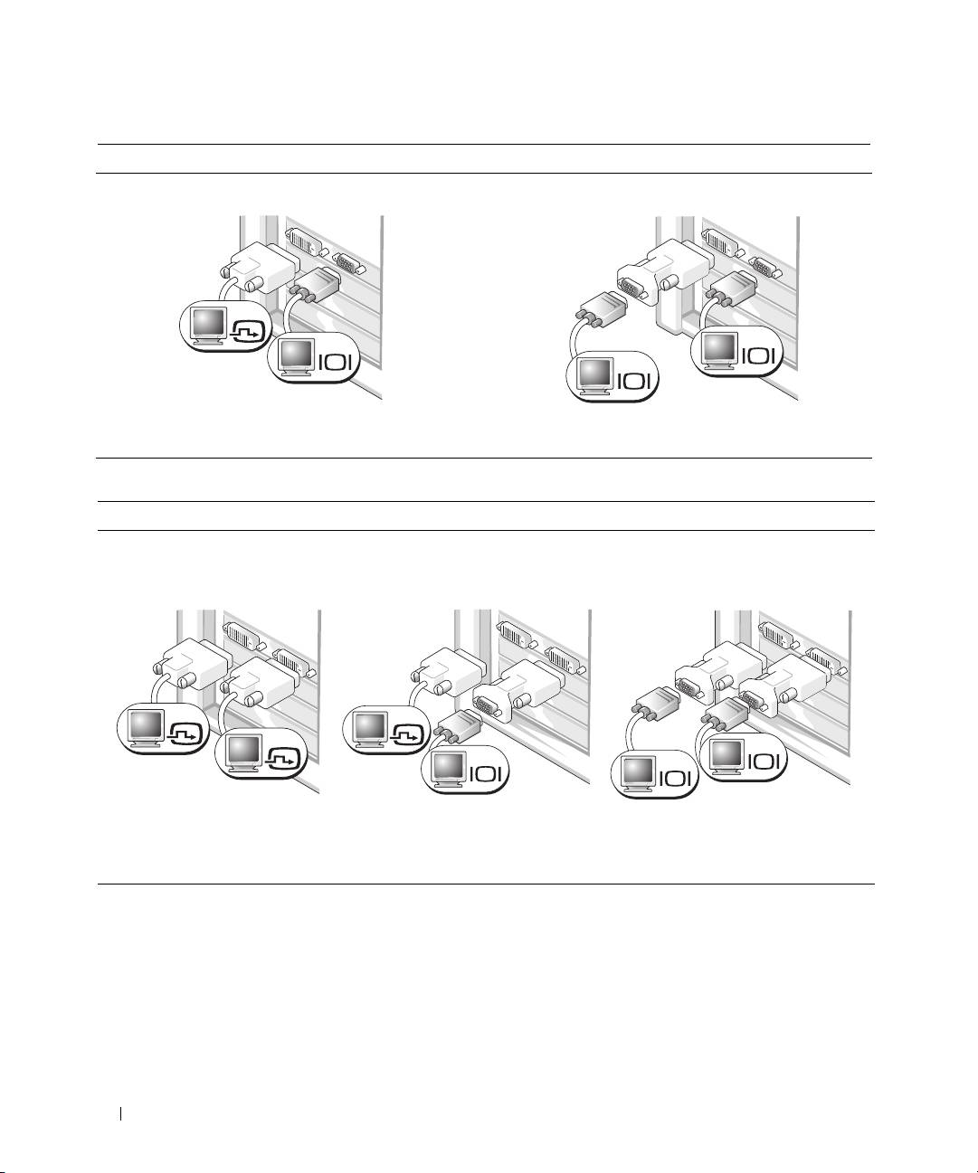
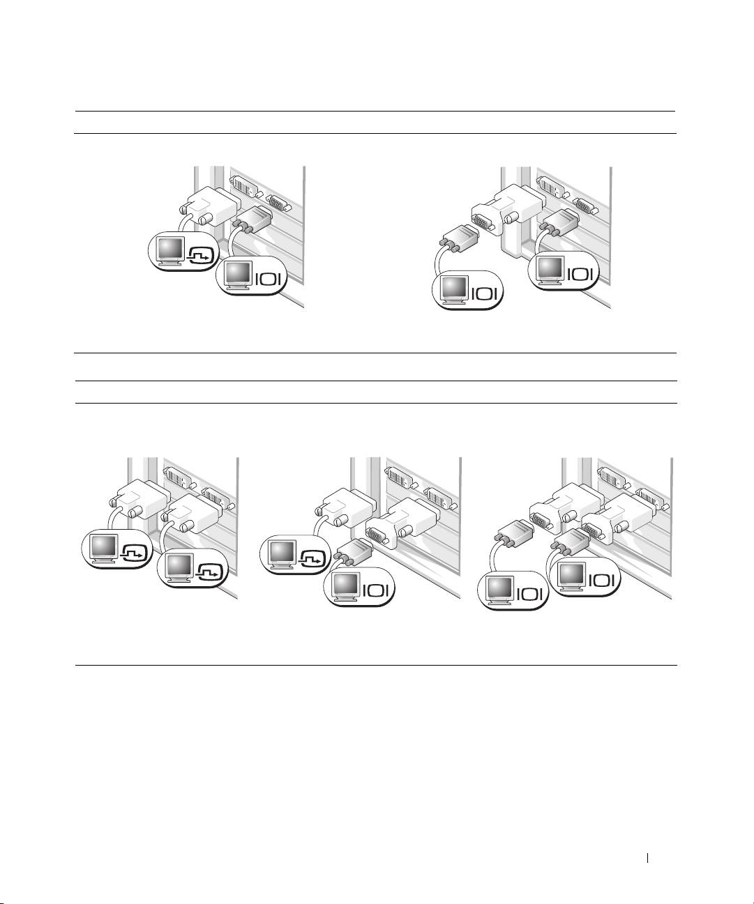
For dual-monitor capable cards with one DVI connector and one VGA connector
One DVI connector and one VGA connector:
Two VGA connectors with one VGA adapter:
DVI
VGA
VGA
VGA
Use the appropriate connector(s) when you want
Use the VGA adapter when you want to connect
to connect your computer to one or two monitors.
your computer to two VGA monitors.
For dual-monitor capable cards with two DVI connectors
Two DVI connectors:
Two DVI connectors
Two DVI connectors
with one VGA adapter:
with two VGA adapters:
DVI
DVI
DVI
VGA
VGA
VGA
Use the DVI connectors
Use the VGA adapter to connect
Use two VGA adapters to connect
to connect your computer
a VGA monitor to one of the
two VGA monitors to the DVI
to one or two DVI monitors.
DVI connectors on your computer
connectors on your computer.
12 Quick Reference Guide
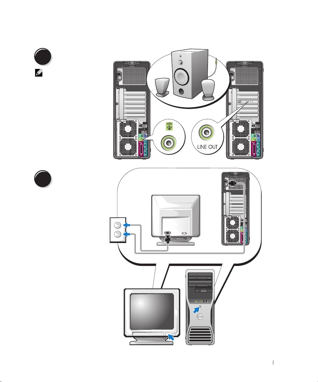
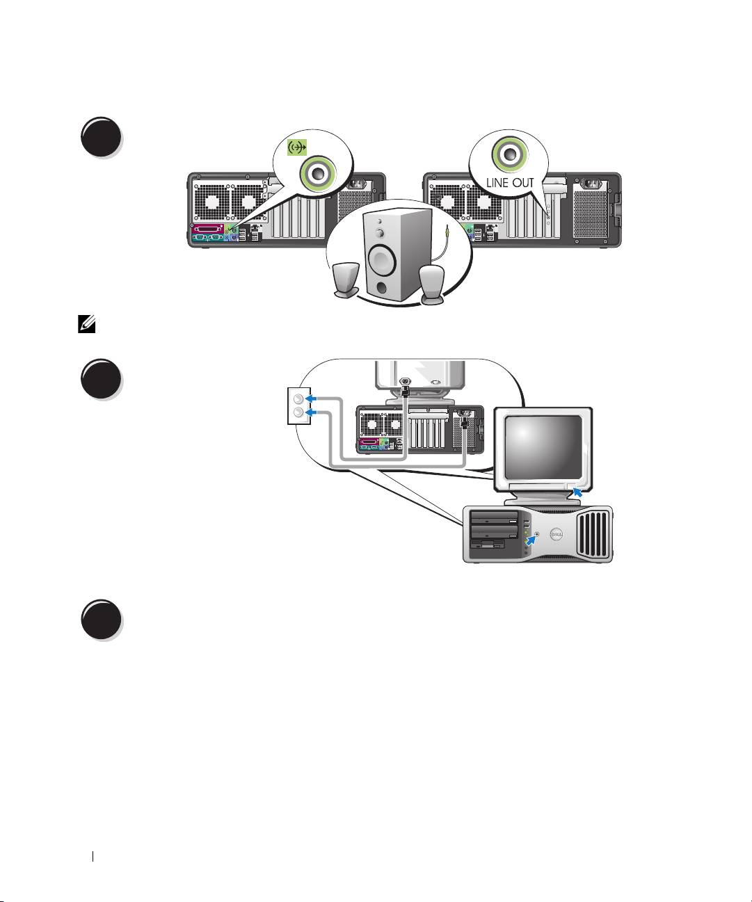
Connect the speakers.
4
NOTE: If your
computer has a sound
card installed, connect
the speakers to
the card.
Connect the power
cables and turn on the
5
computer and monitor.
Quick Reference Guide 13
Install additional software or devices.
6
Before you install any devices or software that did not come with your computer, read the documentation
that came with the software or device or contact the vendor to verify that the software or device is
compatible with your computer and operating system.
You have now completed the setup for your tower computer.
Setting Up Your Computer (Desktop Orientation)
CAUTION: Before you begin any of the procedures in this section, follow the safety instructions in
the Product Information Guide.
You must complete all steps to properly set up your computer.
Connect the keyboard
1
and the mouse.
NOTICE: Do not connect a
modem cable to the network
adapter. Voltage from
telephone communications
can damage the network
adapter.
14 Quick Reference Guide
Connect the modem
2
or the network cable.
NOTE: If your computer
has a network card
installed, connect the
network cable to the card.
Connect the monitor.
3
Depending on your graphics card, you
can connect your monitor in various ways.
NOTE: You may need to use the
provided adapter or cable to connect
your monitor to the computer.
Quick Reference Guide 15
For single- and dual-monitor capable cards with a single connector
VGA adapter:
VGA
Use the VGA adapter when you have a single monitor
graphics card and you want to connect your computer
to a VGA monitor.
Dual VGA Y cable adapter:
Dual DVI Y cable adapter:
VGA
DVI
VGA
DVI
Use the appropriate Y cable when your graphics card
Use the appropriate Y cable when your graphics card has a
has a single connector and you want to connect your
single connector and you want to connect your computer
computer to one or two VGA monitors.
to one or two DVI monitors.
The dual-monitor cable is color-coded; the blue connector is for the primary monitor, and the black
connector is for the second monitor. To enable dual-monitor support, both monitors must be attached
to the computer when you start your computer.
16 Quick Reference Guide
For dual-monitor capable cards with one DVI connector and one VGA connector
One DVI connector and one VGA connector:
Two VGA connectors with one VGA adapter:
DVI
VGA
VGA
VGA
Use the appropriate connector(s) when you want
Use the VGA adapter when you want to connect your
to connect your computer to one or two monitors.
computer to two VGA monitors.
For dual-monitor capable cards with two DVI connectors
Two DVI connectors:
Two DVI connectors
Two DVI connectors
with one VGA adapter:
with two VGA adapters:
DVI
DVI
DVI
VGA
VGA
VGA
Use the DVI connector(s)
Use the VGA adapter to connect
Use two VGA adapters to connect
to connect your computer
a VGA monitor to one of the DVI
two VGA monitors to the DVI
to one or two DVI monitors.
connectors on your computer.
connectors on your computer.
Quick Reference Guide 17
Connect the speakers.
4
NOTE: If your computer has a sound card installed, connect the speakers to the card.
Connect the power cables
and turn on the computer
5
and monitor.
Install additional software or devices.
6
Before you install any devices or software that did not come with your computer, read the documentation
that came with the software or device or contact the vendor to verify that the software or device is
compatible with your computer and operating system.
You have now completed the setup for your desktop computer.
18 Quick Reference Guide
About Your Computer
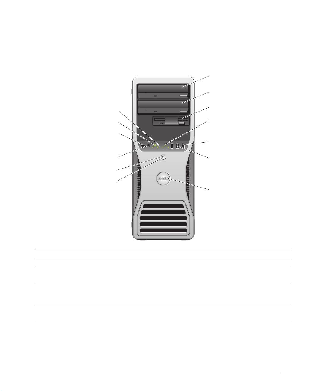
Front View (Tower Orientation)
1 upper 5.25-inch drive bay Holds a CD/DVD drive.
2 lower 5.25-inch drive bay You can use this bay for an optional CD/DVD drive.
3 FlexBay You can use this bay for an optional third hard drive (SATA or SAS), a floppy
drive or Media Card Reader.
4 hard-drive activity light The hard drive light is on when the computer reads data from or writes data to
the hard drive. The light might also be on when a device such as your CD player
is operating.
5 IEEE 1394 connector
Use the optional IEEE 1394 connector for high-speed data devices such as
(optional)
digital video cameras and external storage devices.
Quick Reference Guide 19
1
2
3
13
4
12
11
5
10
6
9
8
7

6 USB 2.0 connectors (2) Use the front USB connectors for devices that you connect occasionally, such as
flash memory keys or cameras, or for bootable USB devices (see
"System Setup"
in your User’s Guide for more information on booting to a USB device).
It is recommended that you use the back USB connectors for devices that
typically remain connected, such as printers and keyboards.
7 Dell™ rotatable badge To rotate the Dell badge for tower-to-desktop conversion; remove the
front
panel
, turn it over, and rotate the plastic handle behind the badge.
8 power button Press to turn on the computer.
NOTICE: To avoid losing data, do not use the power button to turn off the computer.
Instead, perform an operating system shutdown.
NOTE: The power button can also be used to wake the system or to place it into
a power-saving state. See "Power Management" in your User’s Guide for
more information.
9 power light The power light illuminates and blinks or remains solid to indicate different
states:
• No light — The computer is turned off.
• Steady green — The computer is in a normal operating state.
• Blinking green — The computer is in a power-saving state.
• Blinking or solid amber — See "Power Problems" in your
User’s Guide
.
To exit from a power-saving state, press the power button or use the keyboard or
the mouse if it is configured as a wake device in the Windows Device Manager.
For more information about sleep states and exiting from a power-saving state,
see your User’s Guide.
See "Diagnostic Lights" on page 38 for a description of light codes that can help
you troubleshoot problems with your computer.
10 headphone connector Use the headphone connector to attach headphones.
11 microphone connector Use the microphone connector to attach a personal computer microphone for
voice or musical input into a sound or telephony program.
12 network link light The network link light is on when a good connection exists between a 10-Mbps,
100-Mbps, or 1000-Mbps (or 1-Gbps) network and the computer.
13 diagnostic lights (4) Use these lights to help you troubleshoot a computer problem based on the
diagnostic code. For more information, see "Diagnostic Lights" on page 38.
20 Quick Reference Guide
