Dell Precision 390: инструкция
Раздел: Бытовая, кухонная техника, электроника и оборудование
Тип: Компьютер
Инструкция к Компьютеру Dell Precision 390
Оглавление
- Примечания, предупреждения и важная информация Сокращения и аббревиатуры
- Содержание
- Источники информации Возможные направления поиска Где искать
- Возможные направления поиска Где искать
- Возможные направления поиска Где искать
- Возможные направления поиска Где искать
- Установка компьютера (вертикальное положение корпуса) 1
- 2 3
- Видеоплата, поддерживающая один или два монитора, с одним разъемом Двойной адаптер VGA с Y-образным кабелем Двойной адаптер DVI с Y-образным кабелем
- Видеоплаты, поддерживающие два монитора, с одним разъемом DVI и одним разъемом VGA Видеоплата, поддерживающая два монитора, с двумя разъемами DVI
- 4 5
- 6 Установка компьютера (горизонтальное положение корпуса) 1
- 2 3
- Видеоплата, поддерживающая один или два монитора, с одним разъемом Двойной адаптер VGA с Y-образным кабелем Двойной адаптер DVI с Y-образным кабелем
- Видеоплаты, поддерживающие два монитора, с одним разъемом DVI и одним разъемом VGA Видеоплата, поддерживающая два монитора, с двумя разъемами DVI
- 4 5 6
- О компьютере Вид спереди (вертикальное положение корпуса) 5 Индикатор активности жесткого диска
- 14 Индикатор сетевого соединения
- Вид сзади (вертикальное положение корпуса)
- Вид спереди (горизонтальное положение корпуса)
- 13 Индикатор сетевого соединения
- Вид сзади (горизонтальное положение корпуса)
- Разъемы на задней панели
- 11 Разъем клавиатуры Стандартная клавиатура подключается к фиолетовому разъему клавиатуры.
- Вид изнутри
- Цвета кабелей Компоненты системной платы
- Дополнительная информация, содержащаяся в руководстве пользователя
- Чтобы открыть “Руководство пользователя” с жесткого диска выполните указанные ниже действия. Чтобы открыть “Руководство пользователя” на веб-сайте Dell Support, выполните указанные ниже действия. Снятие крышки корпуса компьютера 1 2 3
- 4 5 6 7 8
- Уход за компьютером Решение проблем Советы по поиску и устранению неисправностей Разрешение проблем совместимости программного и аппаратного обеспечения
- Использование функции восстановления системы в Microsoft Windows XP Создание точки восстановления Восстановление прежнего рабочего состояния компьютера
- Отмена последнего восстановления системы Включение функции восстановления системы Использование последней удачной конфигурации
- Другие возможности решения конфликтов аппаратного и программного обеспечения Диагностическая программа Dell Diagnostics Когда использовать диагностическую программу Dell Diagnostics
- Запуск диагностической программы Dell Diagnostics с жесткого диска Запуск диагностической программы Dell Diagnostics с компакт-диска Drivers and Utilities
- Перед началом тестирования Кодовые сигналы Код Причина
- Код Причина Сообщения об ошибках
- индикаторы диагностики Схема включения индикаторов
- Схема включения индикаторов
- Схема включения индикаторов
- Схема включения индикаторов
- Схема включения индикаторов
- Схема включения индикаторов Часто задаваемые вопросы Вопрос Решение Источник дополнительной
- Вопрос Решение Источник дополнительной

Dell Precision™ Workstation 390
Quick Reference Guide
Model DCTA
www.dell.com | support.dell.com

title.fm Page 2 Friday, June 2, 2006 4:24 PM
Notes, Notices, and Cautions
NOTE: A NOTE indicates important information that helps you make better use of your computer.
NOTICE: A NOTICE indicates either potential damage to hardware or loss of data and tells you how to avoid
the problem.
CAUTION: A CAUTION indicates a potential for property damage, personal injury, or death.
Abbreviations and Acronyms
For a complete list of abbreviations and acronyms, see Glossary in your
User’s Guide
.
®
®
If you purchased a Dell™ n Series computer, any references in this document to Microsoft
Windows
operating systems are not applicable.
____________________
Information in this document is subject to change without notice.
© 2006 Dell Inc. All rights reserved.
Reproduction in any manner whatsoever without the written permission of Dell Inc. is strictly forbidden.
Trademarks used in this text: Dell and the DELL logo are trademarks of Dell Inc.; Red Hat is a registered trademark of Red Hat Corporation.
Other trademarks and trade names may be used in this document to refer to either the entities claiming the marks and names or their products.
Dell Inc. disclaims any proprietary interest in trademarks and trade names other than its own.
Model DCTA
May 2006 P/N GH459 Rev. A00

Contents
Finding Information . . . . . . . . . . . . . . . . . . . . . . . . . . . . . . . . 5
Setting Up Your Computer (Tower Orientation)
. . . . . . . . . . . . . . . . . . 9
Setting Up Your Computer (Desktop Orientation)
. . . . . . . . . . . . . . . . 14
About Your Computer
. . . . . . . . . . . . . . . . . . . . . . . . . . . . . . . 19
Front View (Tower Orientation)
. . . . . . . . . . . . . . . . . . . . . . . 19
Back View (Tower Orientation)
. . . . . . . . . . . . . . . . . . . . . . . 21
Front View (Desktop Orientation)
. . . . . . . . . . . . . . . . . . . . . . 22
Back View (Desktop Orientation)
. . . . . . . . . . . . . . . . . . . . . . 24
Back-Panel Connectors
. . . . . . . . . . . . . . . . . . . . . . . . . . 25
Inside View
. . . . . . . . . . . . . . . . . . . . . . . . . . . . . . . . . 27
System Board Components
. . . . . . . . . . . . . . . . . . . . . . . . . . . . 28
Locating Your User’s Guide
. . . . . . . . . . . . . . . . . . . . . . . . . . . 29
Removing the Computer Cover
. . . . . . . . . . . . . . . . . . . . . . . . . . 30
Caring for Your Computer
. . . . . . . . . . . . . . . . . . . . . . . . . . . . 31
Solving Problems
. . . . . . . . . . . . . . . . . . . . . . . . . . . . . . . . 32
Troubleshooting Tips
. . . . . . . . . . . . . . . . . . . . . . . . . . . . 32
Resolving Software and Hardware Incompatibilities
. . . . . . . . . . . 32
Using Microsoft Windows XP System Restore
. . . . . . . . . . . . . . . 32
Using the Last Known Good Configuration
. . . . . . . . . . . . . . . . . 34
Dell Diagnostics
. . . . . . . . . . . . . . . . . . . . . . . . . . . . . . . 34
Before You Start Testing
. . . . . . . . . . . . . . . . . . . . . . . . . . 36
Beep Codes
. . . . . . . . . . . . . . . . . . . . . . . . . . . . . . . . . . . . 36
Error Messages
. . . . . . . . . . . . . . . . . . . . . . . . . . . . . . . 37
Diagnostic Lights
. . . . . . . . . . . . . . . . . . . . . . . . . . . . . . . . . 37
Frequently Asked Questions
. . . . . . . . . . . . . . . . . . . . . . . . . . . 42
Index . . . . . . . . . . . . . . . . . . . . . . . . . . . . . . . . . . . . . . . . . 45
Contents 3

4 Contents
Finding Information
NOTE: Some features may not be available for your computer or in certain countries.
NOTE: Additional information may ship with your computer.
What Are You Looking For? Find It Here
• A diagnostic program for my computer
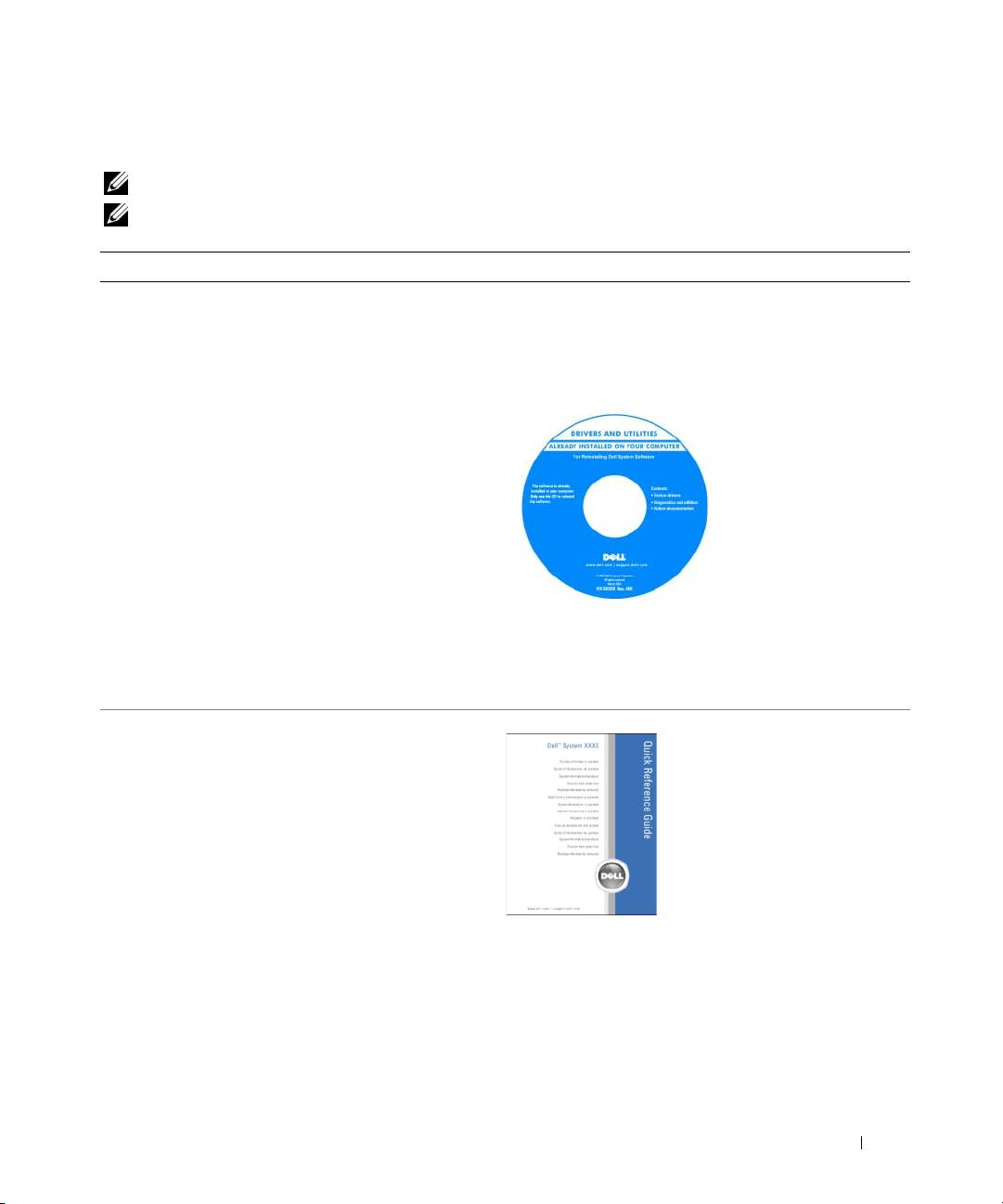
Drivers and Utilities CD (also known as ResourceCD)
• Drivers for my computer
Documentation and drivers are already installed on your
• My computer documentation
computer. You can use the CD to reinstall drivers, run
• My device documentation
the "Dell Diagnostics" on page 34, or access your
documentation.
• Desktop System Software (DSS)
Readme files may be
included on your CD
to provide last-minute
updates about technical
changes to your
computer or advanced
technical-reference
material for technicians
or experienced users.
NOTE: Drivers and documentation updates can be found
at support.dell.com.
NOTE: The Drivers and Utilities CD is optional and may
not ship with your computer.
• How to set up my computer
Quick Reference Guide
• How to care for my computer
• Basic troubleshooting information
• How to run the Dell Diagnostics
• Error codes and diagnostic lights
• How to remove and install parts
• How to open my computer cover
NOTE: The Quick Reference Guide is optional and may
not ship with your computer.
NOTE: This document is available as a PDF at
support.dell.com.
Quick Reference Guide 5
What Are You Looking For? Find It Here
• Warranty information
Dell™ Product Information Guide
• Terms and Conditions (U.S. only)
• Safety instructions
• Regulatory information
• Ergonomics information
• End User License Agreement
• How to remove and replace parts
User’s Guide
• Specifications
®
®
Microsoft
Windows
XP Help and Support Center
• How to configure system settings
1
Click the
Start
button and click
Help and Support
.
• How to troubleshoot and solve problems
2
Click
User’s and system guides
and click
User’s guides
.
The User’s Guide is also available on the optional
Drivers
and Utilities
CD
.
• Service Tag and Express Service Code
Service Tag and Microsoft Windows License
• Microsoft Windows License Label
These labels are located on your computer.
• Use the Service Tag
to identify your
computer when you
use
support.dell.com
or contact technical
support.
• Enter the Express
Service Code to direct your call when contacting
technical support.
6 Quick Reference Guide

What Are You Looking For? Find It Here
• Solutions — Troubleshooting hints and tips, articles
Dell Support Website — support.dell.com
from technicians, online courses, frequently asked
NOTE: Select your region to view the appropriate support
questions
site.
• Community — Online discussion with other Dell
NOTE: Corporate, government, and education customers
customers
can also use the customized Dell Premier Support website
• Upgrades — Upgrade information for components,
at premier.support.dell.com. The website may not be
such as memory, the hard drive, and the operating
available in all regions.
system
• Customer Care — Contact information, service call
and order status, warranty, and repair information
• Service and support — Service call status and support
history, service contract, online discussions with
technical support
• Reference — Computer documentation, details on
my computer configuration, product specifications,
and white papers
• Downloads — Certified drivers, patches, and
software updates
• Desktop System Software (DSS) — If you reinstall
the operating system for your computer, you should
also reinstall the DSS utility. DSS provides critical
updates for your operating system and support for
®
Dell™ 3.5-inch USB floppy drives, Intel
®
Pentium
M processors, optical drives, and USB
devices. DSS is necessary for correct operation of
your Dell computer. The software automatically
detects your computer and operating system and
installs the updates appropriate for your
configuration.
• How to use Windows XP
Windows Help and Support Center
• Documentation for my computer
1
Click the
Start
button and click
Help and Support
.
• Documentation for devices (such as a modem)
2
Type a word or phrase that describes your problem
and click the arrow icon.
3
Click the topic that describes your problem.
4
Follow the instructions on the screen.
Quick Reference Guide 7

What Are You Looking For? Find It Here
• How to reinstall my operating system
Operating System CD
The operating system is already installed on your
computer. To reinstall your operating system, use the
Operating System CD. See your User’s Guide for
instructions.
After you reinstall your
operating system, use
the optional Drivers and
Utilities CD to reinstall
drivers for the devices
that came with your
computer.
Your operating system
product key label is
located on your
computer.
NOTE: The color of your CD varies based on the operating
system you ordered.
NOTE: The Operating System CD is optional and may
not ship with your computer.
• How to use Linux
Dell Supported Linux Sites
• E-mail discussions with users of Dell Precision™
• http://linux.dell.com
products and the Linux operating system
• http://lists.us.dell.com/mailman/listinfo/linux-precision
• Additional information regarding Linux
• http://docs.us.dell.com/docs/software/oslinux/
and my Dell Precision computer
8 Quick Reference Guide
Setting Up Your Computer (Tower Orientation)
CAUTION: Before you begin any of the procedures in this section, follow the safety instructions located
in the Product Information Guide.
You must complete all steps to properly set up your computer.
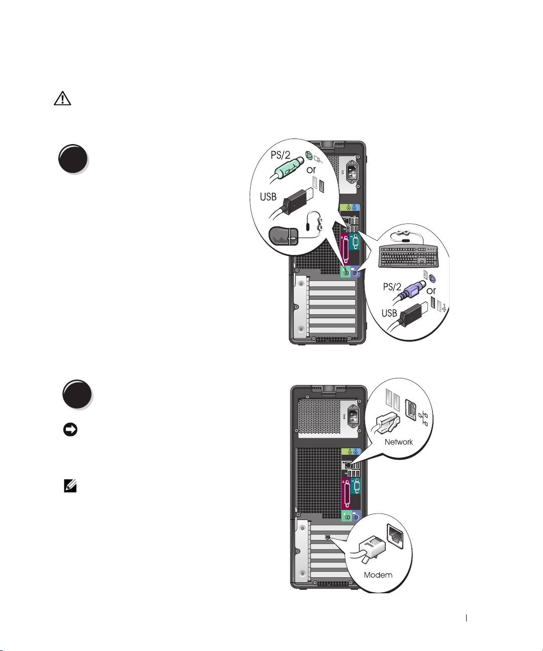
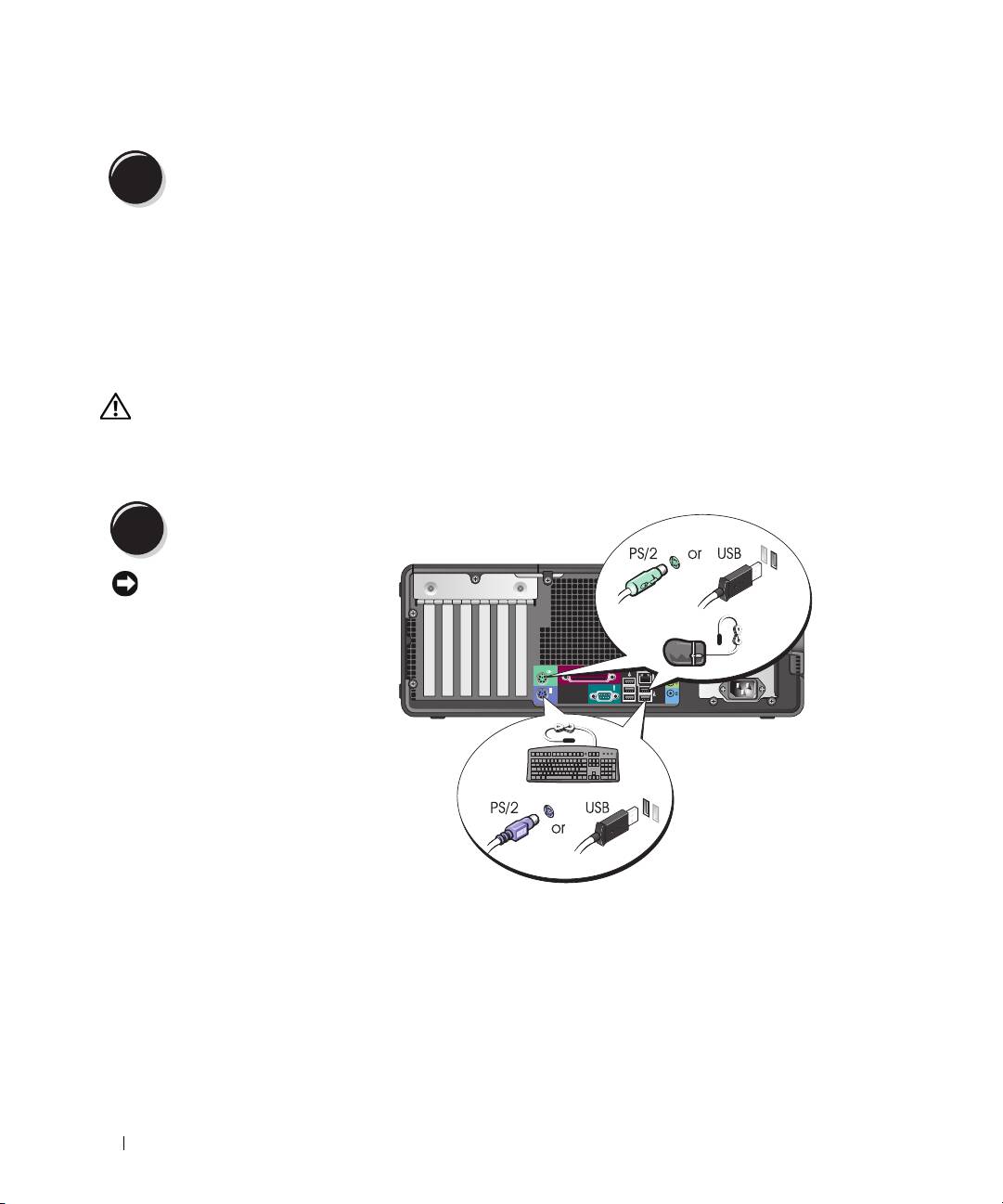
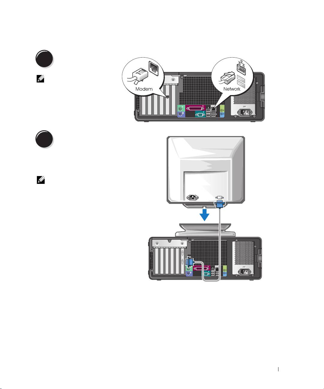
Connect the keyboard and the mouse.
1
Connect the modem or the network cable.
2
NOTICE: Do not connect a modem cable to the
network adapter. Voltage from telephone
communications can damage the network adapter.
NOTE: If your computer has a network card installed,
connect the network cable to the card.
Quick Reference Guide 9
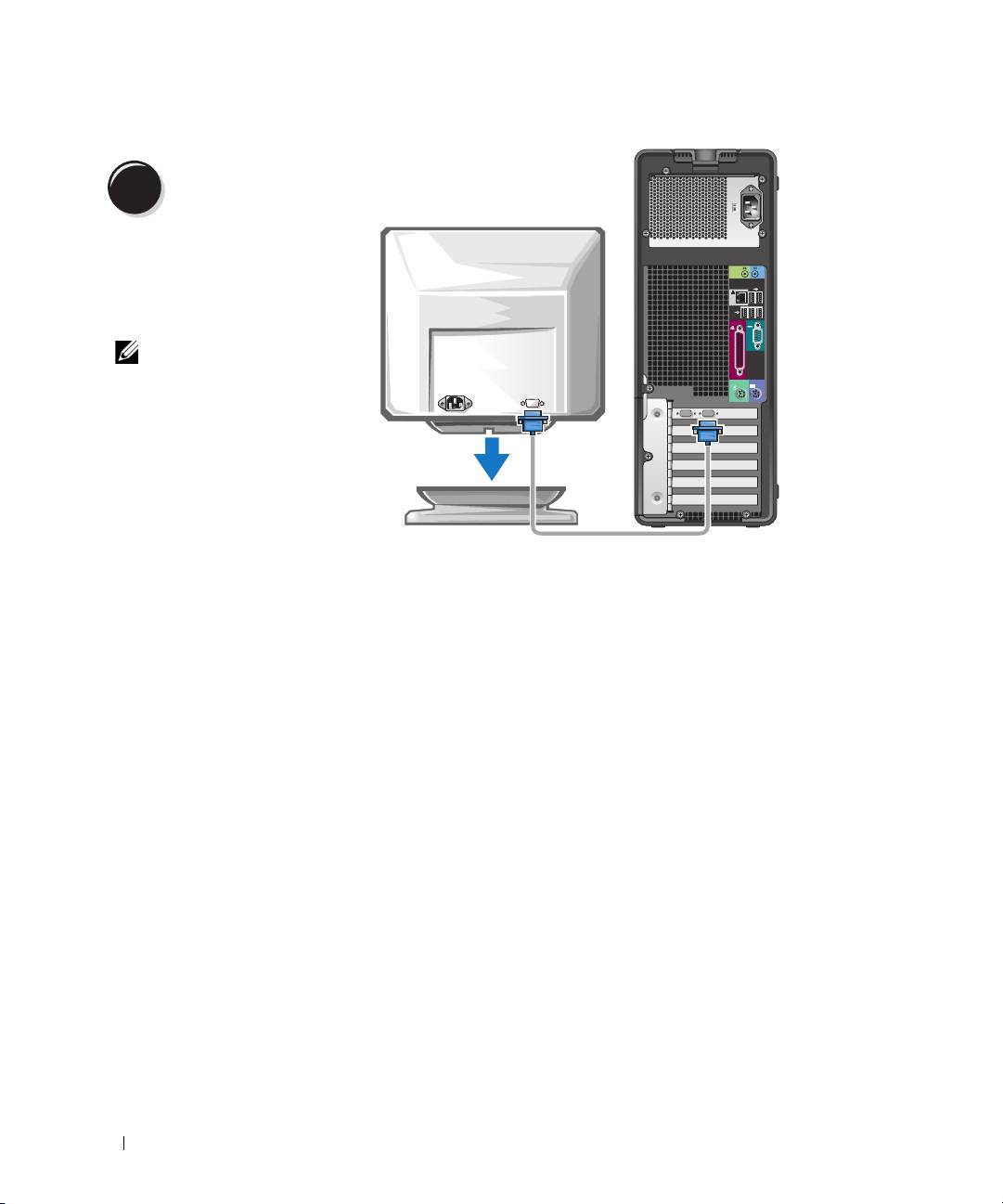
Connect the monitor.
3
Depending on your graphics
card, you can connect your
monitor in various ways.
NOTE: You may need to use
the provided adapter or
cable to connect your
monitor to the computer.
10 Quick Reference Guide
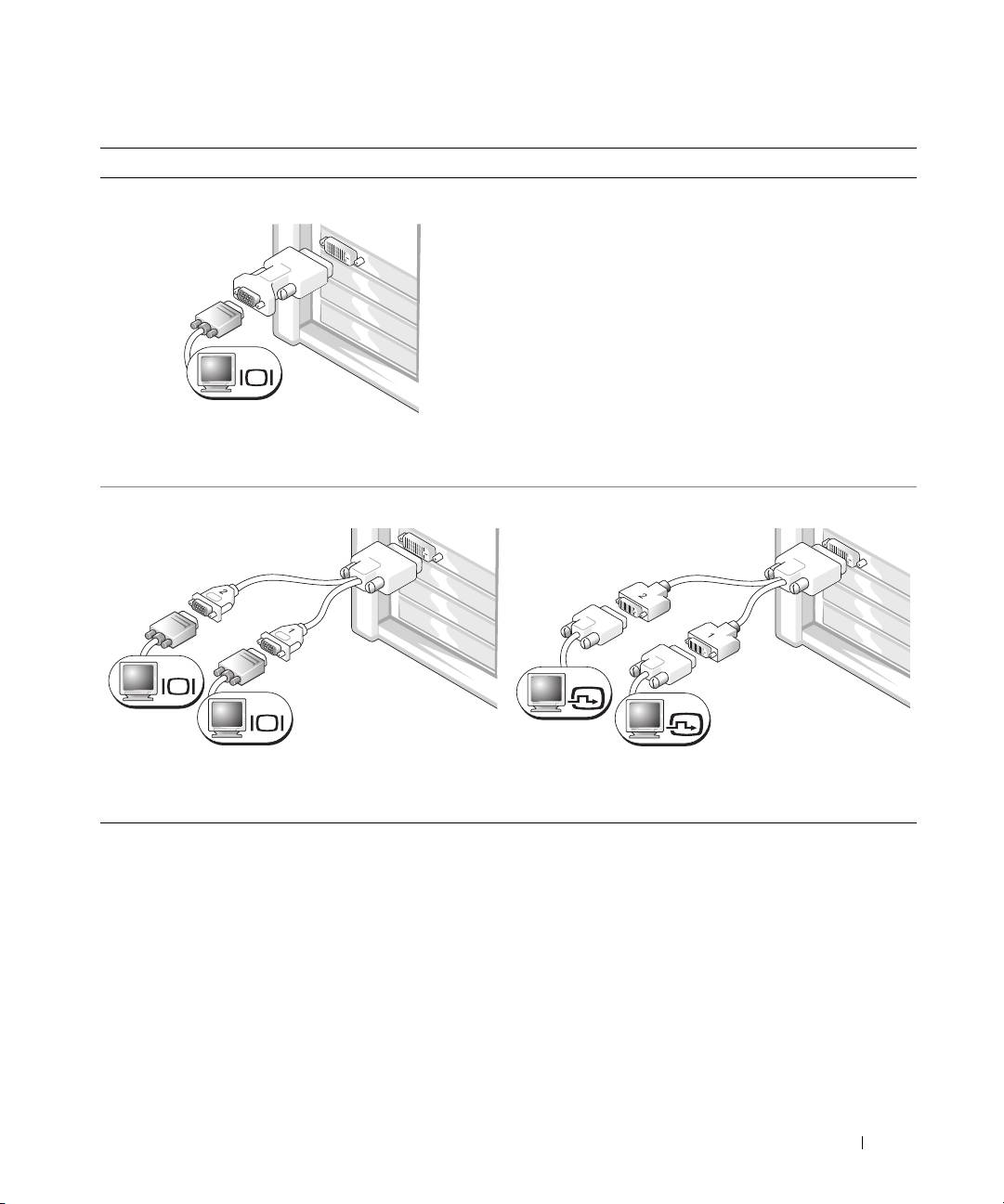
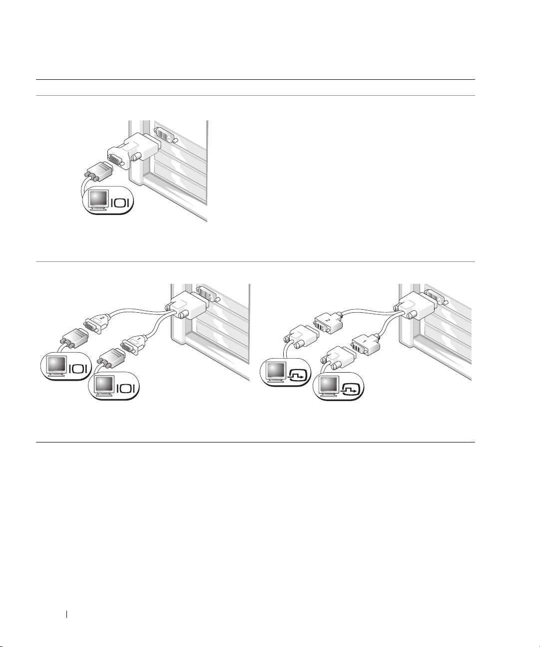
For single- and dual-monitor capable cards with a single connector
One VGA Adapter
VGA
Use the VGA adapter when you have a single-monitor
graphics card and you want to connect your computer
to a VGA monitor.
Dual VGA Y Cable Adapter
Dual DVI Y Cable Adapter
VGA
DVI
VGA
DVI
Use the appropriate Y cable when your graphics card
Use the appropriate Y cable when your graphics card has a
has a single connector and you want to connect your
single connector and you want to connect your computer
computer to one or two VGA monitors.
to one or two DVI monitors.
The dual-monitor cable is color coded; the blue connector is for the primary monitor, and the black
connector is for the secondary monitor. To enable dual-monitor support, both monitors must be attached
to the computer when it starts.
Quick Reference Guide 11
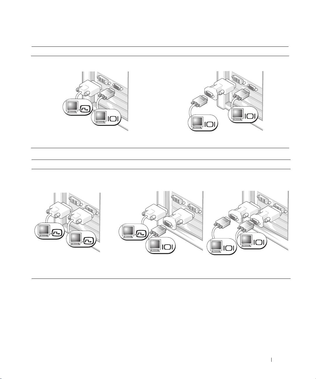
For dual-monitor capable cards with one DVI connector and one VGA connector
One DVI Connector and One VGA Connector
Two VGA Connectors With One VGA Adapter
DVI
VGA
VGA
VGA
Use the appropriate connector(s) when you want
Use the VGA adapter when you want to connect
to connect your computer to one or two monitors.
your computer to two VGA monitors.
For dual-monitor capable cards with two DVI connectors
Two DVI Connectors
Two DVI Connectors With One VGA
Two DVI Connectors With Two VGA
Adapter
Adapters
DVI
DVI
DVI
VGA
VGA
VGA
Use the DVI connectors to connect
Use the VGA adapter to connect
Use two VGA adapters to connect
your computer to one or two DVI
a VGA monitor to one of the DVI
two VGA monitors to the DVI
monitors.
connectors on your computer
connectors on your computer.
12 Quick Reference Guide
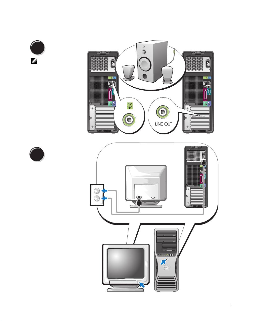
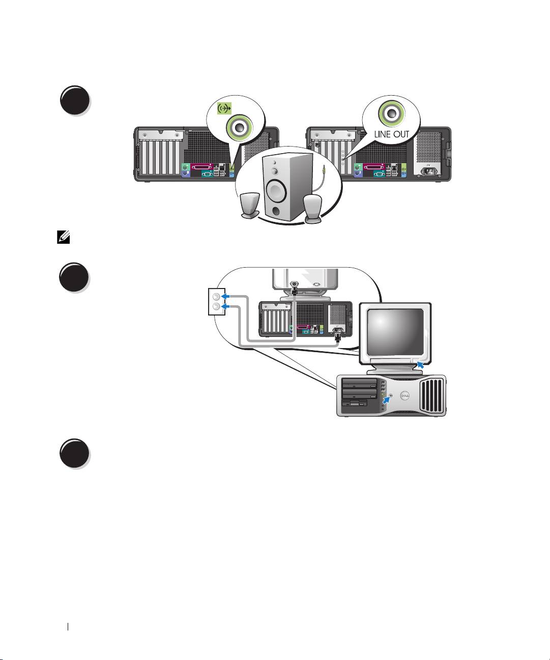
Connect the
4
speakers.
NOTE: If your
computer has a sound
card installed, connect
the speakers to the
card.
Connect the power
5
cables and turn on
the computer and
monitor.
Quick Reference Guide 13
Install additional software or devices.
6
Before you install any devices or software that did not come with your computer, read the documentation
that came with the software or device or contact the vendor to verify that the software or device is
compatible with your computer and operating system.
Congratulations! You have completed the setup for your tower computer.
Setting Up Your Computer (Desktop Orientation)
CAUTION: Before you begin any of the procedures in this section, follow the safety instructions located
in the Product Information Guide.
You must complete all steps to properly set up your computer.
Connect the keyboard and the mouse.
1
NOTICE: Do not connect a
modem cable to the network
adapter. Voltage from
telephone communications
can damage the network
adapter.
14 Quick Reference Guide
Connect the modem
2
or the network cable.
NOTE: If your computer
has a network card
installed, connect the
network cable to the card.
Connect the monitor.
3
Depending on your graphics card,
you can connect your monitor in
various ways.
NOTE: You may need to use the
provided adapter or cable to connect
your monitor to the computer.
Quick Reference Guide 15
For single- and dual-monitor capable cards with a single connector
VGA Adapter
VGA
Use the VGA adapter when you have a single monitor
graphics card and you want to connect your computer
to a VGA monitor.
Dual VGA Y Cable Adapter
Dual DVI Y Cable Adapter
VGA
DVI
VGA
DVI
Use the appropriate Y cable when your graphics card
Use the appropriate Y cable when your graphics card has a
has a single connector and you want to connect your
single connector and you want to connect your computer
computer to one or two VGA monitors.
to one or two DVI monitors.
The dual-monitor cable is color coded; the blue connector is for the primary monitor, and the black
connector is for the secondary monitor. To enable dual-monitor support, both monitors must be attached
to the computer when it starts.
16 Quick Reference Guide
For dual-monitor capable cards with one DVI connector and one VGA connector
One DVI Connector and One VGA Connector
Two VGA Connectors With One VGA Adapter
DVI
VGA
VGA
VGA
Use the appropriate connector(s) when you want
Use the VGA adapter when you want to connect
to connect your computer to one or two monitors.
your computer to two VGA monitors.
For dual-monitor capable cards with two DVI connectors
Two DVI Connectors
Two DVI Connectors With One VGA
Two DVI Connectors With Two VGA
Adapter
Adapters
DVI
DVI
DVI
VGA
VGA
VGA
Use the DVI connector(s) to connect
Use the VGA adapter to connect a
Use two VGA adapters to connect
your computer to one or two DVI
VGA monitor to one of the DVI
two VGA monitors to the DVI
monitors.
connectors on your computer.
connectors on your computer.
Quick Reference Guide 17
Connect the speakers.
4
NOTE: If your computer has a sound card installed, connect the speakers to the card.
Connect the power cables
and turn on the computer
5
and monitor.
Your desktop computer has an
optional front IEEE 1394
connector. This connector is only
available if you purchased an
IEEE 1394 card. To purchase
a card, contact Dell. For
instructions on contacting Dell
and for more information on the
IEEE 1394 card, see your
User’s
Guide
.
Install additional software or devices.
6
Before you install any devices or software that did not come with your computer, read the documentation
that came with the software or device or contact the vendor to verify that the software or device is
compatible with your computer and operating system.
Congratulations! You have completed the setup for your desktop computer.
18 Quick Reference Guide
About Your Computer
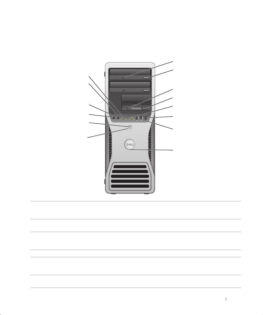
Front View (Tower Orientation)
Quick Reference Guide 19
1
2
14
13
3
4
12
5
11
6
10
7
9
8
1 CD- or DVD-drive
The CD/DVD-drive activity light is on when the computer reads data from or
activity light
writes data to the CD/DVD drive. Wait until this light turns off before you remove
the CD or DVD from the drive.
2 CD- or DVD-drive
Press this button o eject a disc from the CD or DVD drive.
eject button
3 floppy-drive activity
The floppy-drive activity light is on when the computer reads data from or writes
light
data to the optional floppy drive. Wait until this light turns off before you remove
the floppy from the drive.
4 floppy-drive eject button Press this button to eject a floppy disk from the optional floppy drive.
5 hard-drive activity light The hard-drive activity light is on when the computer reads data from or writes
data to the hard drive. The light might also be on when a device such as your CD
player is operating.
6 IEEE 1394 connector
Use the optional IEEE 1394 connectors for high-speed data devices such as digital
(optional)
video cameras and external storage devices.

7 USB 2.0 connectors (2) Use the USB connectors on the front of your computer for devices that you
connect occasionally, such as flash memory keys or cameras, or for bootable USB
devices (see
"System Setup" in your
User’s Guide
for more information on booting
to a USB device).
It is recommended that you use the back USB connectors for devices that typically
remain connected, such as printers and keyboards.
8 Dell badge rotation
To rotate the badge, place your fingers around the outside of the badge, press in,
notch
and turn the badge. You can also rotate the badge by using the slot provided near
the bottom of the badge.
9 power button Press this button to turn the computer on.
NOTE: The power button can also be used to wake the system or to place it into
a power-saving mode. See "Power Management" in the User’s Guide for more
information.
NOTICE: To avoid losing data, do not use the power button to turn the
computer off. Instead, perform an operating system shutdown.
10 power light The power light illuminates and blinks or remains solid to indicate different states:
• No light — The computer is turned off.
• Steady green — The computer is in a normal operating state.
• Blinking green — The computer is in a power-saving mode.
• Blinking or solid amber — See "Power Problems" in the
User’s Guide
.
To exit from a power-saving mode, press the power button or use the keyboard or
the mouse if it is configured as a wake device in the Windows Device Manager. For
more information about sleep modes and exiting from a power-saving mode, see
"Power Management" in the User’s Guide.
See "Diagnostic Lights" on page 37 for a description of light codes that can help
you troubleshoot problems with your computer.
11 microphone connector Use the microphone connector to attach a personal computer microphone for
voice or musical input into a sound or telephony program.
12 headphone connector Use the headphone connector to attach headphones and most kinds of speakers.
13 diagnostic lights (4) Use the lights to help you troubleshoot a computer problem based on the
diagnostic code. For more information, see "Diagnostic Lights" on page 37.
14 network link light The network light is on when the computer sends or receives data over a network
connection. The light might also be on when a network device is establishing a
network connection.
20 Quick Reference Guide
