Dell PowerConnect 2716: инструкция
Раздел: Бытовая, кухонная техника, электроника и оборудование
Тип: Сетевое оборудование
Инструкция к Сетевому оборудованию Dell PowerConnect 2716
Оглавление
- Appendix A: Configuration Examples
- Configuring Interface Parameters

Appendix A: Configuration Examples
This Appendix provides some configuration examples for the PowerConnect 2708/2716/2724
devices installed in the Enterprise Network.
The following configuration scenarios are described:
• Configuring Interface Parameters
• Creating VLAN Membership
• Configuring VLAN Port Settings
• Configuring LAG Membership
• Downloading Software File
• Configuring Port Mirroring
• Configuring Storm Control
• Configuring CoS Priority Queues
1
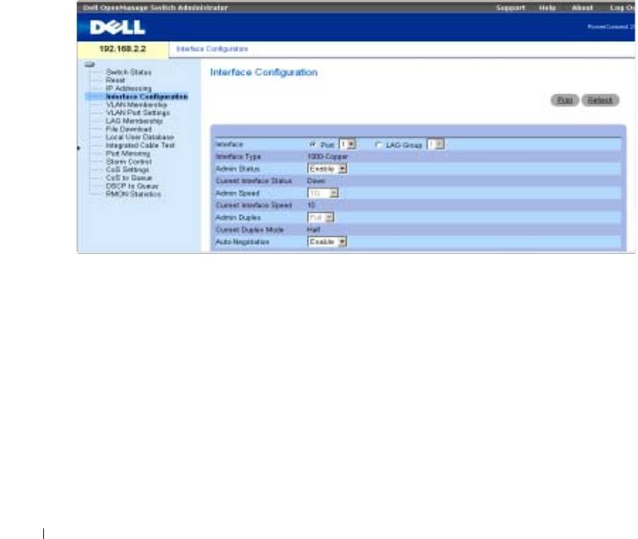
Configuring Interface Parameters
The Interface Configuration screen enables the user to set the various interface parameters,
interface type and additional operational attributes. In the following example, Port 1 is configured
as 1000Mbps Copper interface type, as maximum speed and interface media type. The appropriate
cable type connection is RJ-45 1 Gigabit connection.
The Admin Status is Enabled, therefore traffic is forwarded through the port. The Current
Interface Speed is 10 Mbps as the actual synchronized interface speed. The Admin Duplex mode is
Full Duplex (FDX), supporting transmission in both directions, while the Current Duplex Mode is
configured at Half Duplex (HDX), supporting transmission between the device and the other
station in one direction only. Auto-Negotiation is Enabled, Backpressure is set at Disable, and Flow
Control is set at Disable.
www.dell.com | support.dell.com
Figure 9-1. Interface Configuration
VLANs
VLANs are logical subgroups within a Local Area Network (LAN) that combine user stations and
network devices into a single brodcast domain, regardless of the physical LAN segment to which
they are attached.
VLANs allow network traffic to flow more efficiently within subgroups. VLANs managed through
software reduce the amount of time network changes, additions, and moves are implemented. Port-
based VLANs are comprised of a set of ports that make up a Layer 2 broadcast domain.
The following figure illustrates the concept of VLANs in the Enterprise Network. In this example,
Finance, Marketing and R&D departments are configured as three distinct VLANs in the
enterprise, designated as VLAN #2, VLAN#3 and VLAN#4, respectively.
2
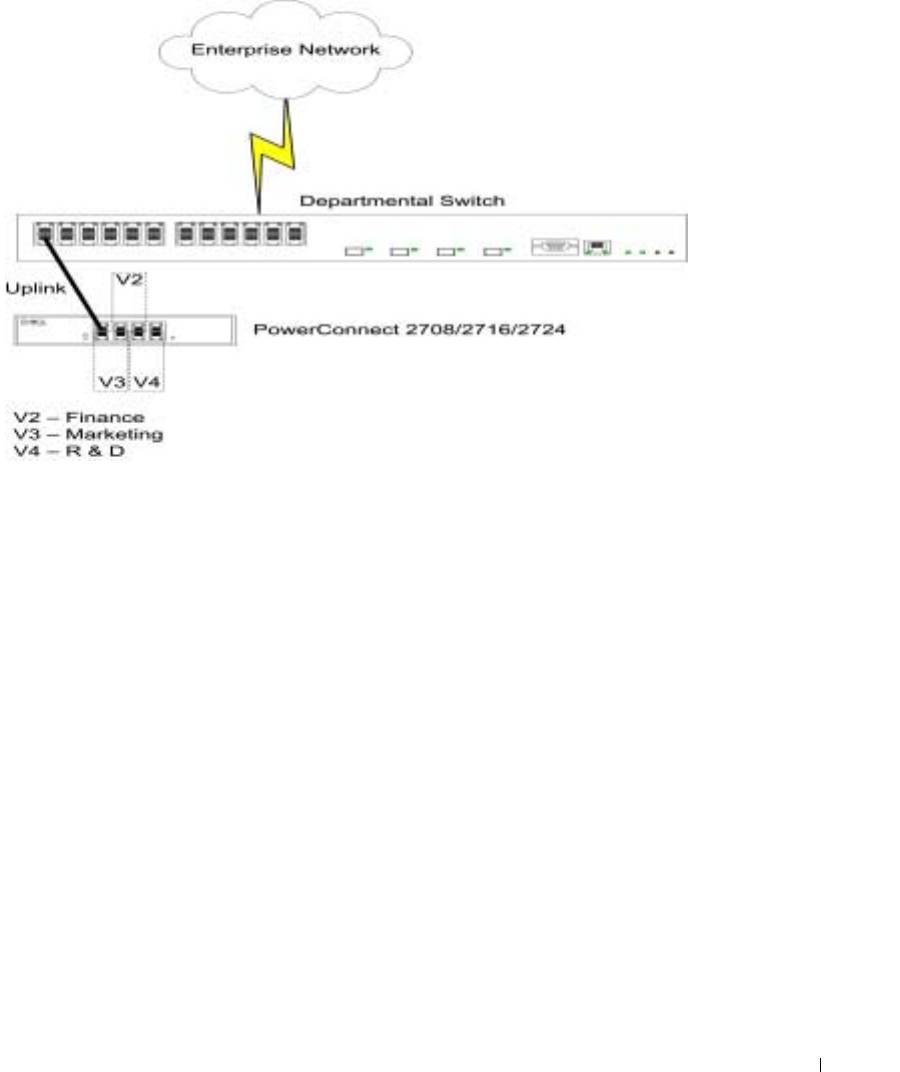
Figure 9-2. Port-Based VLANs in the Enterprise
Creating VLAN Membership
VLANs are collections of switching ports that comprise a single broadcast domain. Packets are
classified as belonging to a VLAN based on either the VLAN tag, or a combination of the ingress
port and packet contents. Packets sharing common attributes can be grouped in the same VLAN.
VLAN tagging provides a method of transferring VLAN information between VLAN groups. VLAN
tagging attaches a 4-byte tag to packet headers. The VLAN tag indicates to which VLAN the packet
belongs. VLAN tags are attached to the packets by either the end station or by the network device.
VLAN tags also contains VLAN network priority information.
VLAN membership is used to partition traffic into several mutually exclusive broadcast domains.
VLAN membership facilitates greater security and pre-defined access levels of user groups in
separate departments.
The VLAN Membership
Web Management page contains fields for defining VLAN groups. The
device supports the mapping of 4094 VLAN IDs to 64 VLANs. All ports must have a defined PVID.
If no other value is configured the default VLAN PVID is used. VLAN ID #1 is the default VLAN,
and cannot be deleted from the system.
The VLAN Membership screen enables the user to select an existing VLAN, create a new VLAN
with port numbers, create a new VLAN port membership, or remove an existing VLAN.
VLAN Membership ports can be defined as Untag Egress packets, Tag Egress packets, or they can
be defined as Not Member.
3
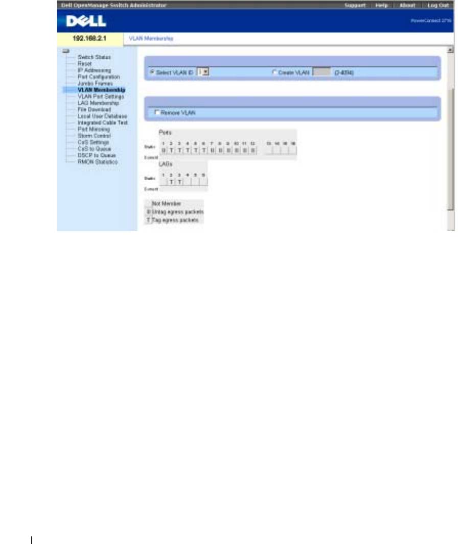
Figure 9-3. VLAN Membership
www.dell.com | support.dell.com
Defining VLAN Port Settings
The VLAN Port Settings screen enables the user to configure information for a specific port in a
LAG. In the following example, port #2 in LAG Group 1, has the Frame Type as Admit All, and
Ingress Filtering is Disabled.
The follwing screen shows the specific status information relevant to a specific port, and global
status information relevant to all ports.
4
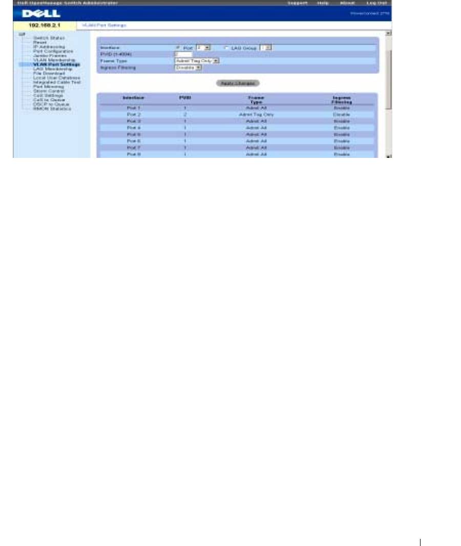
Figure 9-4. VLAN Port Settings
LAGs
A Link Aggregated Group (LAG) is composed of ports with the same speed, set to full-duplex
operation. Up to six Aggregated Links may be defined, each with up to four member ports, to form
a single Link Aggregated Group (LAG). This enables:
• Fault tolerance protection from physical link disruption
• Higher bandwidth connections
• Improved bandwidth granularity
• High bandwidth server connectivity
With the departmental PowerConnect 2708/2716/2724 switches installed, network redundancy and
improved traffic performance are facilitated. The PowerConnect device serves to connect the
departmental groups of users to another switch that is located on another floor. In addition, LAGs
are used to ensure that a backup, in case one line is disabled.
The following figure illustrates the concept of Aggragated Links in the switch.
5
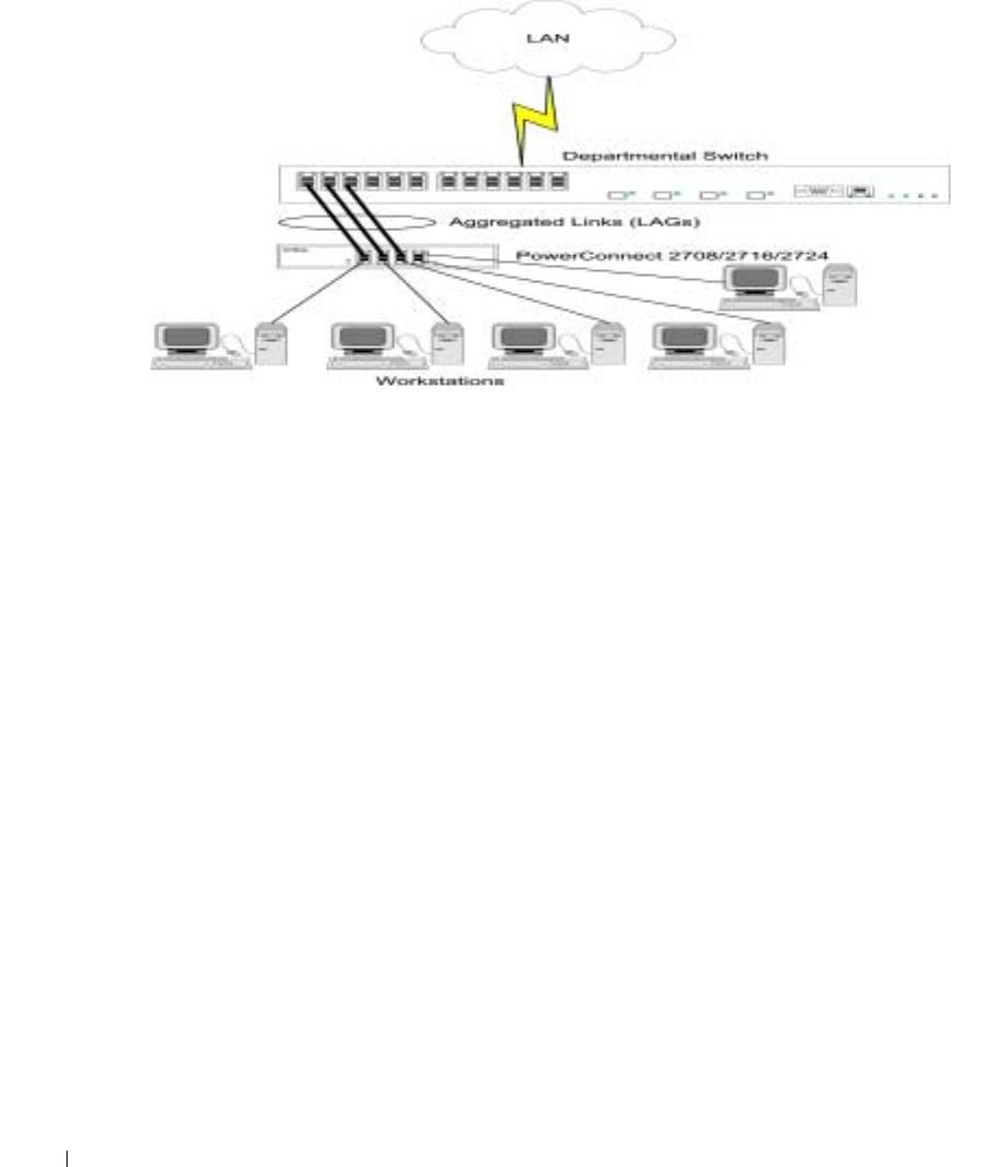
Figure 9-5. LAGs in the PowerConnect Departmental Switch
www.dell.com | support.dell.com
Aggregating Ports
Link Aggregation optimizes port usage by linking a group of ports together to form a single LAG
(aggregated group). Aggregating ports multiplies the bandwidth between the devices, increases
port flexibility, and provides link redundancy.
Consider the following when aggregating ports:
• Link Aggregation is allowed between two devices only.
• All ports within a LAG must be the same media type.
• A VLAN is not configured on the port.
• The port is not assigned to a different LAG.
• An available MAC address exists which can be assigned to a port.
• Auto-negotiation mode is not configured on the port.
• The port is in full-duplex mode.
• All ports in the LAG have the same ingress filtering and tagged modes.
• All ports in the LAG have the same back pressure and flow control modes.
• All ports in the LAG have the same priority.
• All ports in the LAG have the same transceiver type.
• The device supports up to six LAGs, and up to four ports in each LAG.
Ports added to a LAG do not their individual port configuration. When ports are removed from the
LAG,
the original port configuration is applied to the ports.
The device considers an Aggregated
Link a single logical port.
6
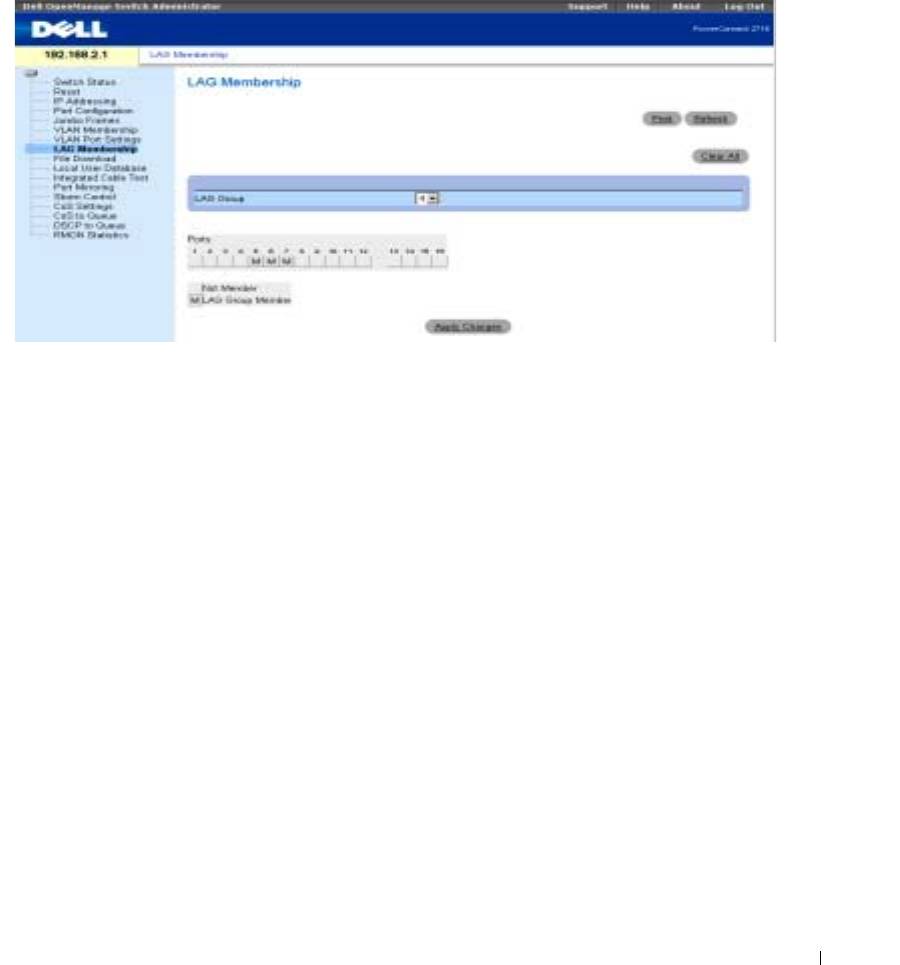
Configuring LAG Membership
The following screen shows an example of Link Aggregation configuration, whereby LAG Group 4
consists of member ports 5, 6, and 7.
Figure 9-6. LAG Membership
Downloading Files from Server
The File Download screen enables the user to configure and update Software Image files or BootP
Image files in the PowerConnect 2708/2716/2724 devices.
The TFTP Server IP Address specifies the location from which files are donloaded. The File Name
specifies the file to be downloaded. The Destination File can be either the Software Image file, or
the Boot Code image.
NOTE: The TFTP Server application can be either downloaded from Internet public domains, or purchased
from software vendors.
7
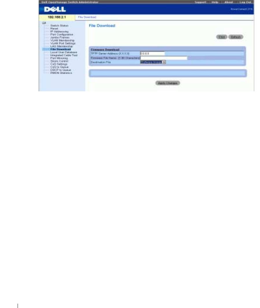
Figure 9-7. File Download
www.dell.com | support.dell.com
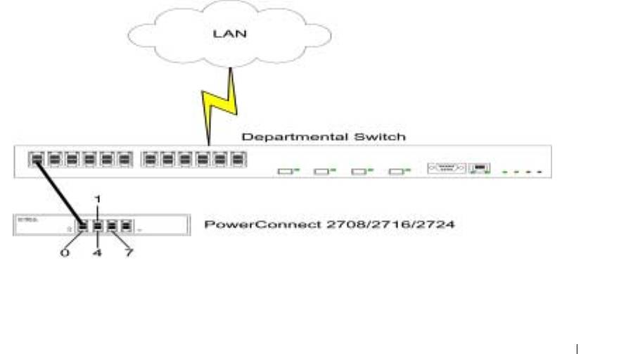
Port Mirroring
PowerConnect 2708/2716/2724 support port mirroring functionality. Port Mirroring allows traffic to
be copied from one port to another port. Port mirroring monitors and mirrors network traffic by
forwarding copies of incoming and outgoing packets from a monitored port to a monitoring port.
The user can specify which target port receives copies of all traffic passing through a specified
source port.
The Port Mirroring feature enables the Network Administator to perfom network monitoring and
debugging, detecting and troubleshooting network traffic problems, faulty NICs, and isolating
communication problems in the network.
The following figure illustrates the concept of Port Mirroring. In this example, port 7 is the Source
Port in the device, and port 3 is the Destination port. In this scheme, the Destination Port monitors
and copies all incoming and outgoing traffic on the Source Port. The Network Administrator can
connect to port 3 a sniffer or some other network traffic analyzer.
8
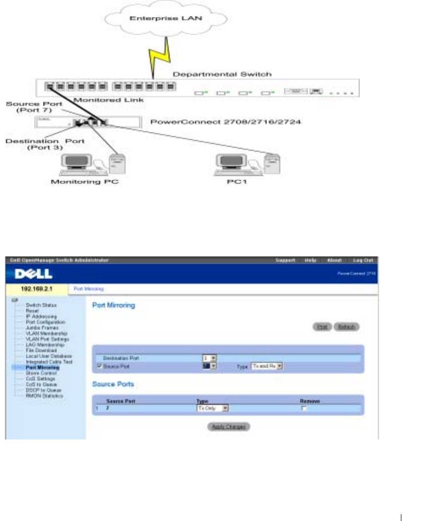
Figure 9-8. Port Mirroring Setup with Departmental Switch
In the following screen, the Destination Port is configured as port 3, and the Source Port as port 7.
The type of traffic to be monitored is configured as Tx (Transmit) and Rx (Receive). The user can
elect to add/remove ports to be mirrored and monitored on the network, as required.
Figure 9-9. Port Mirroring
9
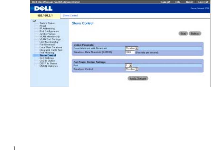
Storm Control
Enabling Storm Control
The Storm Control mechanism is useful when a faulty Network Interface Card (NIC), or Broadcast
or Multicast frames cause network flooding, beyond the threshold rate limit. When Layer 2 frames
are forwarded, Broadcast and Multicast frames cause flooding to all ports on the relevant VLAN.
This occupies bandwidth, and loads all nodes connected on all ports.
The Network Administrator moderates the network traffic by setting the threshold so as to limit, or
disables the Storm Control operation, therefore limiting the amount of Multicast and Broadcast
frames accepted and forwarded by the PowerConnect 2708/2716/2724 device.
In the example shown in the following screen, the Broadcast Rate Threshold is configured to 1000
www.dell.com | support.dell.com
packets per second. Count Multicast with Broadcast is Enabled, and Broadcast Control is Enabled.
NOTE: The threshold rate limit is defined by the Network Administrator, according to the characteristics of the
network to be monitored, and the applications running on the network.
NOTE: The Storm Control screen below applies to the PowerConnect 2716 and PowerConnect 2724 devices.
Figure 9-10. Storm Control
10
Configuring Class of Service (CoS)
The underlying mechanism of Class of Service (CoS) is the concept of queues. After packets are
assigned to a specific egress queue, CoS services can be assigned to the queue(s). The
PowerConnect 2708/2716/2724 system supports four queues per port for service priorities, where
queue 0 is the lowest priority and queue 3 is the highest priority. For each logical group of priorities
defined by the user, two priority levels are defined.
Egress queues are configured with a scheduling scheme by one of the following methods:
Strict Priority —
Ensures that time-sensitive applications are always forwarded. Strict Priority (SP)
allows the prioritization of mission-critical, time-sensitive traffic over less time-sensitive
applications. For example, under Strict Priority, voice over IP traffic can be prioritized so the IP
traffic is forwarded before FTP or e-mail traffic.
Weighted Round Robin —
Ensures that a single application does not dominate the device
forwarding capacity. Weighted Round Robin (WRR) forwards entire queues in a Round Robin
order. All queues can participate in WRR, with expect SP queues. SP queues are serviced before
WRR queues. If the traffic flow is minimal, and SP queues do not occupy the whole bandwidth
allocated to a port, the WRR queues can share the bandwidth with the SP queues.
Ensuring the remaining bandwidth is distributed according to the weight ratio. If WRR is selected,
the following weights are assigned to the queues: 1, 2, 4, 8.
The following figure illustrates the concept of CoS priority queues managed by the device. In this
scenario, priorities are assigned to untagged incoming packets, per port.
Figure 9-11. CoS Priority Queues
11
The common prioritization mechanisms implemented in the PowerConnect device are Class of
Service (CoS), according to IEEE802.1p, and DSCP (DiffServe Code Point) for IP traffic. CoS
reduces flow complexity by mapping multiple flows into eight classes of service. These classes
are set in the VPT (VLAN Priority Tag) 4-byte field tag, added to the packet by either a station
or networking device. The device provides mapping of CoS classes to 4 priority queues per port
(values are 1 to 4, where 1 is the lowest value, and 4 is the highest). For untagged packets service
priority class can be assigned per port. The service class value in the VPT always overrides the
service priority class defined per port.
DSCP provides a method of prioritizing IP packets, and indicates the service level desired in the
network. Incoming IP packets arrive with a DSCP value and are mapped to four priority queues,
based on the priority DSCP value assigned to them. The values are 1 to 4, where 1 is the lowest
value and 4 is the highest.
www.dell.com | support.dell.com
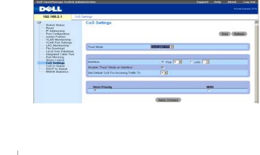
Via the CoS Setting screen, the user can assign priority to untagged packets through configuring
the ports ports. This screen contains fields for enabling or disabling CoS.
The CoS global parameters are configured via the CoS Settings screen. The Trust Mode relies on
predefined fields within the packet that determine the egress queue. The possible values for Trust
Mode are None (traffic is mapped to best effort queue q2), CoS (default value), and DSCP.
In the following example, for the configured Interface Port 5, the Trust Mode is configured as CoS
(determined by IEEE802.1p) —this is the Trust Mode default value. Disable "Trust" Mode on
Interface is checked— this setting overrides the Trust Mode on the Ethernet globally.
Figure 9-12. CoS Settings
Mapping CoS Values to Queues
In the following screen, CoS values are mapped to an egress queue. CoS priority tag values are zero
as the lowest, and 7 as the highest. There are four traffic priority queues supported .
12
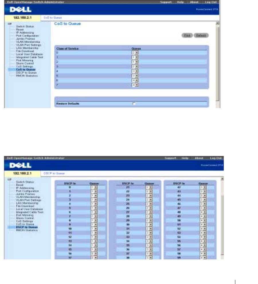
When Restore Defaults box is checked, the device’s factory default settings for mapping CoS
values are restored.
Figure 9-13. CoS to Queue
Mapping DSCP Values to Queues
The following screen shows DSCP In incoming traffic and the priority queues (1 to 4) assigned to
them.
Figure 9-14. DSCP to Queues
13

www.dell.com | support.dell.com
14
