Dell PowerEdge VRTX: инструкция
Раздел: Бытовая, кухонная техника, электроника и оборудование
Тип: Компьютер
Инструкция к Компьютеру Dell PowerEdge VRTX
Оглавление

Dell PowerEdge M620 Systems (For Dell PowerEdge
VRTX Enclosure)
Owner's Manual
Regulatory Model: HHB
Regulatory Type: HHB003

Notes, Cautions, and Warnings
NOTE: A NOTE indicates important information that helps you make better use of your computer.
CAUTION: A CAUTION indicates either potential damage to hardware or loss of data and tells you how to avoid the
problem.
WARNING: A WARNING indicates a potential for property damage, personal injury, or death.
© 2013 Dell Inc.
Trademarks used in this text:
Dell
™
, the Dell logo,
Dell Boomi
™
,
Dell Precision
™
,
OptiPlex
™
,
Latitude
™
,
PowerEdge
™
,
PowerVault
™
,
PowerConnect
™
,
OpenManage
™
,
EqualLogic
™
,
Compellent
™
,
KACE
™
,
FlexAddress
™
,
Force10
™
and
Vostro
™
are trademarks of Dell
Inc.
Intel
®
,
Pentium
®
,
Xeon
®
,
Core
®
and
Celeron
®
are registered trademarks of Intel Corporation in the U.S. and other countries.
AMD
®
is a registered trademark and
AMD Opteron
™
,
AMD Phenom
™
and
AMD Sempron
™
are trademarks of Advanced Micro Devices, Inc.
Microsoft
®
,
Windows
®
,
Windows Server
®
,
Internet Explorer
®
,
MS-DOS
®
,
Windows Vista
®
and
Active Directory
®
are either trademarks
or registered trademarks of Microsoft Corporation in the United States and/or other countries.
Red Hat
®
and
Red Hat
®
Enterprise Linux
®
are registered trademarks of Red Hat, Inc. in the United States and/or other countries.
Novell
®
and
SUSE
®
are
registered trademarks of Novell Inc. in the United States and other countries.
Oracle
®
is a registered trademark of Oracle Corporation
and/or its affiliates.
Citrix
®
,
Xen
®
,
XenServer
®
and
XenMotion
®
are either registered trademarks or trademarks of Citrix Systems, Inc. in
the United States and/or other countries.
VMware
®
,
vMotion
®
,
vCenter
®
,
vCenter SRM
™
and
vSphere
®
are registered trademarks or
trademarks of VMware, Inc. in the United States or other countries.
IBM
®
is a registered trademark of International Business Machines
Corporation.
2013–05
Rev. A00
Contents
1 About Your System......................................................................................................................7
Introduction.............................................................................................................................................................. 7
Front-Panel Features And Indicators....................................................................................................................... 8
Using USB Diskette Or USB DVD/CD Drives.............................................................................................................8
Hard-Drive Features................................................................................................................................................. 8
Other Information You May Need.............................................................................................................................9
2 Using The System Setup And Boot Manager.......................................................................11
Choosing The System Boot Mode.......................................................................................................................... 11
Entering System Setup............................................................................................................................................12
Responding To Error Messages.......................................................................................................................12
Using The System Setup Navigation Keys....................................................................................................... 12
System Setup Options.............................................................................................................................................12
System Setup Main Screen..............................................................................................................................13
System BIOS Screen........................................................................................................................................13
System Information Screen..............................................................................................................................13
Memory Settings Screen................................................................................................................................. 14
Processor Settings Screen.............................................................................................................................. 14
SATA Settings Screen......................................................................................................................................15
Boot Settings Screen....................................................................................................................................... 16
Integrated Devices Screen.............................................................................................................................. 16
Serial Communications Screen........................................................................................................................17
System Profile Settings Screen........................................................................................................................18
System Security Screen...................................................................................................................................19
Miscellaneous Settings....................................................................................................................................19
System And Setup Password Features.................................................................................................................. 20
Assigning A System And/Or Setup Password..................................................................................................20
Using Your System Password To Secure Your System....................................................................................21
Deleting Or Changing An Existing System And/Or Setup Password................................................................21
Operating With A Setup Password Enabled.................................................................................................... 22
Entering The UEFI Boot Manager........................................................................................................................... 22
Using The Boot Manager Navigation Keys......................................................................................................22
Boot Manager Screen......................................................................................................................................23
UEFI Boot Menu............................................................................................................................................... 23
Embedded System Management............................................................................................................................23
iDRAC Settings Utility..............................................................................................................................................24
Entering The iDRAC Settings Utility..................................................................................................................24
3 Installing Server Module Components.................................................................................. 25
Recommended Tools.............................................................................................................................................. 25
Installing And Removing A Server Module.............................................................................................................25
Removing A Server Module............................................................................................................................. 25
Installing A Server Module...............................................................................................................................27
Opening And Closing The Server Module...............................................................................................................27
Opening The Server Module............................................................................................................................ 27
Closing The Server Module..............................................................................................................................28
Inside The Server Module...................................................................................................................................... 29
Cooling Shroud....................................................................................................................................................... 29
Removing The Cooling Shroud......................................................................................................................... 29
Installing The Cooling Shroud.......................................................................................................................... 30
System Memory......................................................................................................................................................30
General Memory Module Installation Guidelines............................................................................................ 32
Mode-Specific Guidelines................................................................................................................................33
Sample Memory Configurations.......................................................................................................................34
Removing Memory Modules............................................................................................................................ 37
Installing Memory Modules............................................................................................................................. 38
PCIe Mezzanine Cards............................................................................................................................................39
Removing A PCIe Mezzanine Card...................................................................................................................39
Installing A PCIe Mezzanine Card....................................................................................................................40
Management Riser Card.........................................................................................................................................41
Replacing The SD Card.................................................................................................................................... 41
Internal USB Key.............................................................................................................................................. 42
SD vFlash Card........................................................................................................................................................43
Replacing The SD vFlash Card......................................................................................................................... 43
Network Daughter Card/LOM Riser Card............................................................................................................... 43
Removing The Network Daughter Card/LOM Riser Card.................................................................................43
Installing The Network Daughter Card/LOM Riser Card..................................................................................44
Processors..............................................................................................................................................................45
Removing A Processor.....................................................................................................................................45
Installing A Processor......................................................................................................................................49
Hard Drives............................................................................................................................................................. 50
Hard Drive/SSD Installation Guidelines........................................................................................................... 50
Removing A Hard Drive/SSD............................................................................................................................ 50
Installing A Hard Drive/SSD............................................................................................................................. 51
Shutdown Procedure For Servicing a Hard Drive............................................................................................51
Configuring The Boot Drive.............................................................................................................................. 52
Removing A Hard Drive/SSD From A Hard-Drive/SSD Carrier.........................................................................52
Installing A Hard Drive/SSD In A Hard-Drive/SSD Carrier...............................................................................52
Hard-Drive/SSD Backplane.................................................................................................................................... 53
Removing The Hard-Drive/SSD Backplane......................................................................................................53
Installing The Hard-Drive/SSD Backplane.......................................................................................................54
System Board..........................................................................................................................................................54
Removing The System Board........................................................................................................................... 54
Installing The System Board............................................................................................................................ 55
NVRAM Backup Battery......................................................................................................................................... 56
Replacing The NVRAM Backup Battery.......................................................................................................... 56
Storage Controller Card..........................................................................................................................................57
Removing The Storage Controller Card............................................................................................................57
Installing The Storage Controller Card.............................................................................................................58
4 Troubleshooting Your System................................................................................................. 59
Safety First—For You and Your System..................................................................................................................59
Troubleshooting System Memory...........................................................................................................................59
Troubleshooting Hard Drives..................................................................................................................................60
Troubleshooting USB Devices................................................................................................................................60
Troubleshooting An Internal SD Card.....................................................................................................................61
Troubleshooting Processors...................................................................................................................................61
Troubleshooting The Server Module System Board.............................................................................................. 61
Troubleshooting The NVRAM Backup Battery.......................................................................................................62
5 Using System Diagnostics....................................................................................................... 63
Dell Online Diagnostics...........................................................................................................................................63
Dell Embedded System Diagnostics....................................................................................................................... 63
When To Use The Embedded System Diagnostics.......................................................................................... 63
Running The Embedded System Diagnostics...................................................................................................64
Running Embedded System Diagnostics From An External Media..................................................................64
System Diagnostic Controls............................................................................................................................. 64
6 Jumpers And Connectors........................................................................................................ 65
System Board Jumper Settings.............................................................................................................................. 65
System Board Connectors......................................................................................................................................66
Disabling A Forgotten Password............................................................................................................................ 67
7 Technical Specifications......................................................................................................... 69
8 System Messages.....................................................................................................................73
LCD Status Messages.............................................................................................................................................73
Viewing LCD Messages................................................................................................................................... 73
Removing LCD Messages.................................................................................................................................73
System Error Messages..........................................................................................................................................73
Warning Messages...............................................................................................................................................142
Diagnostic Messages........................................................................................................................................... 142
Alert Messages.....................................................................................................................................................142
9 Getting Help..............................................................................................................................143
Contacting Dell..................................................................................................................................................... 143
1
About Your System
Introduction
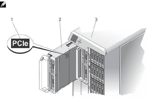
This document provides information on the Dell PowerEdge M620 server module that is specifically configured for the
PowerEdge VRTX enclosure, and can be identified by a label marked PCIe on the server module.
NOTE: This server module is not supported on the Dell PowerEdge M1000e enclosure with the PowerEdge VRTX
mezzanine card.
Figure 1. Identifying Server Module Configured for the VRTX Enclosure
1. PCIe label on the server module
2. server module
7
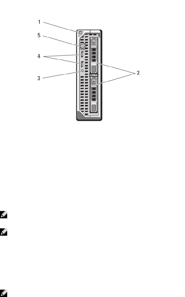
Front-Panel Features And Indicators
Figure 2. Front-Panel Features and Indicators
1. Server module handle release button
4. USB connectors (2)
2. Hard drives/SSDs (2)
5. Server module power button
3. Status/identification indicator
Using USB Diskette Or USB DVD/CD Drives
The server module has USB ports on the front which allow you to connect a USB diskette drive, USB flash drive, USB
DVD/CD drive, keyboard, or mouse. The USB drives can be used to configure the server module.
NOTE: Your server module supports only Dell-branded USB 2.0 drives. Use the optional external drive storage tray
to support the drive while in use.
NOTE: If the drive must be designated as the boot drive, connect the USB drive, restart the system, then enter the
System Setup and set the drive as first in the boot sequence. The USB device is displayed in the boot order setup
screen only if it is attached to the system before you run the System Setup. You can also select the boot device by
pressing <F11> during system start-up and selecting a boot device for the current boot sequence.
Hard-Drive Features
Your system supports two 2.5 inch SSD, SAS or SATA hard drives.
NOTE: SSD/SAS/SATA hard drives cannot be mixed within a server module.
The hard-disk drives plug into the hard-drive backplane inside the server module. On server modules with a diskless
configuration, all hard drive slots must be filled with hard-drive blanks, and the hard-drive backplane must still be
installed to maintain proper airflow.
The hard-drive indicators display different patterns as drive events occur in the system.
8
NOTE: The server module must have a hard drive or a hard-drive blank installed in each hard-drive bay.
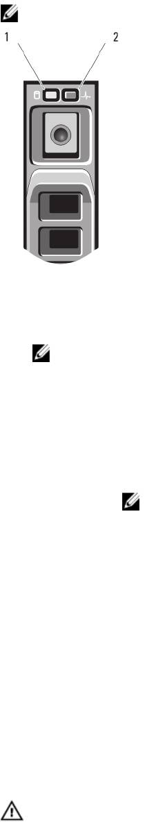
Figure 3. Hard-Drive Indicators
1. hard-drive activity indicator (green)
2. hard-drive status indicator (green and amber)
NOTE: If the hard drive is in Advanced Host Controller Interface (AHCI) mode, the status LED (on the right
side) does not function and remains off.
Drive-Status
Condition
Indicator Pattern
Blinks green two
Identifying drive or preparing for removal
times per second
Off Drive ready for insertion or removal
NOTE: The drive status indicator remains off until all hard drives are initialized after system
power is applied. Drives are not ready for insertion or removal during this time.
Blinks green, amber,
Drive predicted failure
and off
Blinks amber four
Drive failed
times per second
Blinks green slowly Drive rebuilding
Steady green Drive online
Blinks green three
Rebuild aborted
seconds, amber three
seconds, and off six
seconds
Other Information You May Need
WARNING: See the safety and regulatory information that shipped with your system. Warranty information may be
included within this document or as a separate document.
9

• The Getting Started Guide for the VRTX enclosure provides an overview of the VRTX enclosure and the server
modules, setting up your system, and technical specifications.
• The
Dell PowerEdge VRTX Enclosure Owner’s Manual
provides information about the VRTX enclosure features
and describes how to troubleshoot the enclosure and install or replace the enclosure's components. This
document is available online at dell.com/poweredgemanuals.
• The
Dell Chassis Management Controller for Dell PowerEdge VRTX User’s Guide
provides information on
installing, configuring and using the Chassis Management Controller (CMC) for the VRTX enclosure. This
document is available online at dell.com/esmmanuals.
• Dell systems management application documentation provides information about installing and using the
systems management software.
• Any media that ships with your system that provides documentation and tools for configuring and managing your
system, including those pertaining to the operating system, system management software, system updates, and
system components that you purchased with your system.
NOTE: Always check for updates on dell.com/support/manuals and read the updates first because they often
supersede information in other documents.
10

2
Using The System Setup And Boot Manager
System Setup enables you to manage your system hardware and specify BIOS-level options.
NOTE: You can access System Setup by mapping the server module to the KVM on the VRTX enclosure. To map the
server to the KVM using LCD — From the Main Menu screen on the LCD, go to KVM Mapping and select the
server, and then press OK. You can also access the System Setup through iDRAC remote console.
You can also map a server module to the KVM using the CMC web interface. For more information, see the
Dell
Chassis Management Controller for Dell PowerEdge VRTX User’s Guide
at dell.com/esmmanuals.
The following keystrokes provide access to system features during startup:
Keystroke Description
<F2> Enters the System Setup.
<F10> Enters System Services, which opens the Dell Lifecycle Controller 2 (LC2). The Dell LC2 allows
you to access utilities such as embedded system diagnostics. For more information, see the
Dell LC2 documentation.
<F11> Enters the BIOS Boot Manager or the Unified Extensible Firmware Interface (UEFI) Boot
Manager, depending on the system's boot configuration.
<F12> Starts Preboot eXecution Environment (PXE) boot.
From the System Setup, you can:
• Change the NVRAM settings after you add or remove hardware
• View the system hardware configuration
• Enable or disable integrated devices
• Set performance and power management thresholds
• Manage system security
You can access the System Setup using the:
• Standard graphical browser, which is enabled by default
• Text browser, which is enabled using Console Redirection
To enable Console Redirection, in System Setup, select System BIOS → Serial Communication screen → Serial
Communication, select On with Console Redirection.
NOTE: By default, help text for the selected field is displayed in the graphical browser. To view the help text in the
text browser, you must press <F1>.
Choosing The System Boot Mode
System Setup enables you to specify the boot mode for installing your operating system:
• BIOS boot mode (the default) is the standard BIOS-level boot interface.
11

• UEFI boot mode is an enhanced 64-bit boot interface based on Unified Extensible Firmware Interface (UEFI)
specifications that overlays the system BIOS.
You must select the boot mode in the Boot Mode field of the Boot Settings Screen of System Setup. Once you specify the
boot mode, the system boots in the specified boot mode and you proceed then to install your operating system from that
mode. Thereafter, you must boot the system in the same boot mode (BIOS or UEFI) to access the installed operating
system. Trying to boot the operating system from the other boot mode will cause the system to halt at startup.
NOTE: Operating systems must be UEFI-compatible to be installed from the UEFI boot mode. DOS and 32-bit
operating systems do not support UEFI and can only be installed from the BIOS boot mode.
NOTE: For the latest information on supported operating systems, see dell.com/support.
Entering System Setup
1. Turn on or restart your system.
2. Press <F2> immediately after you see the following message:
<F2> = System Setup
If your operating system begins to load before you press <F2>, allow the system to finish booting, and then restart
your system and try again.
Responding To Error Messages
If an error message is displayed while the system is booting, make a note of the message. See System Error Messages
section of this manual for an explanation of the message and suggestions for correcting errors.
NOTE: After installing a memory upgrade, it is normal for your system to display a message the first time you start
your system.
Using The System Setup Navigation Keys
Keys Action
Up arrow Moves to the previous field.
Down arrow Moves to the next field.
<Enter> Allows you to type in a value in the selected field (if applicable) or follow the link in the field.
Spacebar Expands or collapses a drop-down list, if applicable.
<Esc> Moves to the previous page until you view the main screen. Pressing <Esc> in the main screen
exits System Setup. A message prompts you to save any unsaved changes.
<F1> Displays the System Setup help file.
NOTE
: For most of the options, any changes that you make are recorded but do not take effect until you restart the
system.
System Setup Options
12

System Setup Main Screen
NOTE: Press <Alt><F> to reset the BIOS or UEFI settings to their default settings.
Menu Item Description
System BIOS This option is used to view and configure BIOS settings.
iDRAC Settings This option is used to view and configure iDRAC settings.
Device Settings This option is used to view and configure device settings.
System BIOS Screen
NOTE: The options for System Setup change based on the system configuration.
NOTE: System Setup defaults are listed under their respective options in the following sections, where applicable.
Menu Item Description
System Information Displays information about the system such as the system model name, BIOS version, Service
Tag, and so on.
Memory Settings Displays information and options related to installed memory.
Processor Settings Displays information and options related to the processor such as speed, cache size, and so
on.
SATA Settings Displays options to enable or disable the integrated SATA controller and ports.
Boot Settings Displays options to specify the boot mode (BIOS or UEFI). Enables you to modify UEFI and BIOS
boot settings.
Integrated Devices Displays options to enable or disable integrated device controllers and ports, and to specify
related features and options.
Serial Communication Displays options to enable or disable the serial ports and specify related features and options.
System Profile
Displays options to change the processor power management settings, memory frequency,
Settings
and so on.
System Security Displays options to configure the system security settings like, system password, setup
password, TPM security, and so on. It also enables or disables support for local BIOS update
and the power button on the system.
Miscellaneous
Displays options to change the system date, time, and so on.
Settings
System Information Screen
Menu Item
Description
System Model Name Displays the system model name.
System BIOS Version Displays the BIOS version installed on the system.
13

Menu Item Description
System Service Tag Displays the system Service Tag.
System Manufacturer Displays the name of system manufacturer.
System Manufacturer
Displays the contact information of the system manufacturer.
Contact Information
Memory Settings Screen
Menu Item Description
System Memory Size Displays the amount of memory installed in the system.
System Memory Type Displays the type of memory installed in the system.
System Memory
Displays the system memory speed.
Speed
System Memory
Displays the system memory voltage.
Voltage
Video Memory Displays the amount of video memory.
System Memory
Specifies whether system memory tests are run during system boot. Options are Enabled and
Testing
Disabled. By default, the System Memory Testing option is set to Disabled.
Memory Operating
Specifies the memory operating mode. The options available depending on the memory
Mode
configuration of your system are Optimizer Mode, Advanced ECC Mode, Mirror Mode, Spare
Mode, and Spare with Advanced ECC Mode. By default, the Memory Operating Mode option is
set to Optimizer Mode.
Node Interleaving If this field is Enabled, memory interleaving is supported if a symmetric memory configuration is
installed. If Disabled, the system supports Non-Uniform Memory architecture (NUMA)
(asymmetric) memory configurations. By default, Node Interleaving option is set to Disabled.
Processor Settings Screen
Menu Item Description
Logical Processor Allows you to enable or disable logical processors and display the number of logical
processors. If the Logical Processor option is set to Enabled, the BIOS displays all the logical
processors. If this option is set to Disabled, the BIOS only displays one logical processor per
core. By default, the Logical Processor option is set to Enabled.
QPI Speed Allows you to set the QuickPath Interconnect data rate settings. By default, the QPI Speed
option is set to Maximum data rate.
NOTE: The QPI Speed option is displayed only when both the processors are installed.
Alternate RTID
Allows you to allocate more RTIDs to the remote socket increasing cache performance
(Requestor
between the sockets or work in normal mode for NUMA. By default, the Alternate RTID
Transaction ID)
(Requestor Transaction ID) Setting is set to Disabled.
Setting
14

Menu Item Description
Virtualization
Allows you enable or disable the additional hardware capabilities provided for virtualization. By
Technology
default, the Virtualization Technology option is set to Enabled.
Adjacent Cache Line
Allows you to optimize the system for applications that require high utilization of sequential
Prefetch
memory access. By default, the Adjacent Cache Line Prefetch option is set to Enabled. You can
disable this option for applications that require high utilization of random memory access.
Hardware Prefetcher Allows you to enable or disable hardware prefetcher. By default, the Hardware Prefetcher
option is set to Enabled.
DCU Streamer
Allows you to enable or disable DCU streamer prefetcher. By default, the DCU Streamer
Prefetcher
Prefetcher option is set to Enabled.
DCU IP Prefetcher Allows you to enable or disable DCU IP prefetcher. By default, the DCU IP Prefetcher option is
set to Enabled.
Execute Disable Allows you enable or disable execute disable memory protection technology. By default, the
Execute Disable option is set to Enabled.
Number of Cores per
Allows you to control the number of enabled cores in each processor. By default, the Number
Processor
of Cores per Processor option is set to All.
Processor 64-bit
Specifies if the processor(s) support 64-bit extensions.
Support
Processor Core
Displays the maximum core frequency of the processor.
Speed
Processor Bus Speed Displays the bus speed of the processors.
NOTE: The processor bus speed option is displayed only when both the processors are
installed.
Processor
X
Family-
Displays the family and model number of each processor. A submenu displays the core speed,
Model-Stepping
the amount of cache memory, and the number of cores of the processor(s).
SATA Settings Screen
Menu Item Description
Embedded SATA Allows the embedded SATA to be set to Off, ATA, AHCI, or RAID modes. By default, Embedded
SATA is set to AHCI.
Port A Auto enables BIOS support for the device attached to SATA port A. Off disables BIOS support
for the device. By default, Port A is set to Auto.
Port B Auto enables BIOS support for the device attached to SATA port B. Off disables BIOS support
for the device. By default, Port B is set to Auto.
15

Boot Settings Screen
Menu Item Description
Boot Mode Allows you to set the boot mode of the system.
CAUTION: Switching the boot mode may prevent the system from booting if the operating
system is not installed in the same boot mode.
If the operating system supports UEFI, you can set this option to UEFI. Setting this field to BIOS
allows compatibility with non-UEFI operating systems. By default, the Boot Mode option is set
to BIOS.
NOTE: Setting this field to UEFI disables BIOS Boot Settings menu. Setting this field to
BIOS disables the UEFI Boot Settings menu.
Boot Sequence Retry Allows you to enable or disable the boot sequence retry feature. If this field is enabled and the
system fails to boot, the system reattempts the boot sequence after 30 seconds. By default, the
Boot Sequence Retry option is set to Disabled.
BIOS Boot Settings Allows you to enable or disable BIOS Boot options.
NOTE: This option is enabled only if the boot mode is BIOS.
UEFI Boot Settings Allows you to enable or disable UEFI Boot options.
NOTE: This option is enabled only if the boot mode is UEFI.
One-Time Boot Allows you to enable or disable a one-time boot from a selected device.
Integrated Devices Screen
Menu Item Description
Integrated RAID
Allows you to enable or disable the integrated RAID controller. By default, the Integrated RAID
Controller
Controller option is set to Enabled.
User Accessible USB
Allows you enable or disable the user accessible USB ports. Selecting Only Back Ports On
Ports
disables the front USB ports and selecting All Ports Off disables both front and back USB ports.
By default, the User Accessible USB Ports option is set to All Ports On.
Internal USB Port Allows you to enable or disable the internal USB port. By default, the Internal USB Port option
is set to On.
Internal SD Card Port Enables or disables the system’s internal SD card port. By default, Internal SD Card Port option
is set to On.
NOTE: This option is displayed only if IDSDM is installed on the system board.
Internal SD Card
If set to Mirror mode, data is written on both SD cards. If any one of the SD card fails, data is
Redundancy
written to the active SD card. Data from this card is copied to the replacement SD card at the
next boot. By default, Internal SD Card Redundancy option is set to Mirror.
16

Menu Item Description
NOTE: This option is displayed only if IDSDM is installed on the system board.
Integrated Network
Allows you to enable or disable the integrated network card 1. By default, the Integrated
Card 1
Network Card 1 option is set to Enabled.
OS Watchdog Timer Allows you to enable or disable the OS watchdog timer. When this field is enabled, the
operating system initializes the timer and the OS watchdog timer helps in recovering the
operating system. By default, the OS Watchdog Timer option is set to Disabled.
Embedded Video
Allows you to enable or disable the Embedded Video Controller. By default, the embedded
Controller
video controller is Enabled.
SR-IOV Global Enable Allows you to enable or disable the BIOS configuration of Single Root I/O Virtualization (SR-
IOV) devices. By default, the SR-IOV Global Enable option is set to Disabled.
Mezzanine Slot
Allows you to enable or disable available PCIe mezzanine card slots on your system. The Slot
Disablement
Disablement feature controls the configuration of PCIe mezzanine cards installed in the
specified slot.
CAUTION: Slot disablement must be used only when the installed peripheral card is
preventing booting into the Operating System or causing delays in system startup. If the
slot is disabled, both the Option ROM and UEFI driver are disabled.
NOTE: Use this option only for troubleshooting purposes. If one or more of the PCIe
mezzanine card slots are disabled, an error message is displayed during system startup.
For proper operation, make sure that the server module has two Dell PCIe mezzanine
cards installed and both cards are set to Enabled.
NOTE: The Boot Driver Disabled option does not apply to the M620 when operating in the
PowerEdge VRTX chassis. Selecting this option will have the same result as selecting
Enabled.
Serial Communications Screen
Menu Item Description
Serial Communication Allows you to enable the COM port or Console Redirection options.
Serial Port Address Allows you to set the port address for serial devices. By default, the Serial Port Address option
is set to COM1.
NOTE: Only Serial Device 2 can be used for Serial Over LAN (SOL). To use console
redirection by SOL, configure the same port address for console redirection and the serial
device.
Failsafe Baud Rate Displays the failsafe baud rate for console redirection. The BIOS attempts to determine the
baud rate automatically. This failsafe baud rate is used only if the attempt fails and the value
must not be changed. By default, the Failsafe Baud Rate option is set to 11520.
Remote Terminal
Allows you to set the remote console terminal type. By default, the Remote Terminal Type
Type
option is set to VT 100/VT220.
17

Menu Item Description
Redirection After
Allows you to enable or disable to the BIOS console redirection when the operating system is
Boot
loaded. By default, the Redirection After Boot option is set to Enabled.
System Profile Settings Screen
Menu Item Description
System Profile Allows you to set the system profile. If you set the System Profile option to a mode other than
Custom, the BIOS automatically sets the rest of the options. You can only change the rest of the
options if the mode is set to Custom. By default, the System Profile option is set to Performance
Per Watt Optimized (DAPC). DAPC is Dell Active Power Controller.
NOTE: The following parameters are available only when the System Profile is set to
Custom.
CPU Power
Allows you to set the CPU power management. By default, the CPU Power Management option
Management
is set to System DBPM (DAPC). DBPM is Demand-Based Power Management.
Memory Frequency Allows you to set the memory frequency. By default, the Memory Frequency option is set to
Maximum Performance.
Turbo Boost Allows you to enable or disable the processor to operate in turbo boost mode. By default, the
Turbo Boost option is set to Enabled.
C1E Allows you to enable or disable the processor to switch to a minimum performance state when
it is idle. By default, the C1E option is set to Enabled.
C States Allows you to enable or disable the processor to operate in all available power states. By
default, the C States option is set to Enabled.
Monitor/Mwait Allows you to enable Monitor/Mwait instructions in the processor. By default, the Monitor/
Mwait option is set to Enabled for all system profiles, except Custom.
NOTE: This option can be disabled only if the C States option in Custom mode is disabled.
NOTE: When C States is enabled in Custom mode, changing the Monitor/Mwait setting
does not impact system power/performance.
Memory Patrol Scrub Allows you to set the memory patrol scrub frequency. By default, the Memory Patrol Scrub
option is set to Standard.
Memory Refresh Rate Allows you to set the memory refresh rate. By default, the Memory Refresh Rate option is set to
1x.
Memory Operating
Allows you to set the DIMM voltage selection. When set to Auto, the system automatically sets
Voltage
the system voltage to the optimal setting based on the DIMM capacity and the numbers of
DIMMs installed. By default, the Memory Operating Voltage option is set to Auto.
Collaborative CPU
When set to enabled, the CPU power management is controlled by the OS DBPM and the
Performance Control
System DBPM (DAPC). By default, the option is set to Disabled
18

System Security Screen
Menu Item Description
Intel AES-NI The Intel AES-In option improves the speed of applications by performing encryption and
decryption using the Advanced Encryption Standard set and is set to Enabled by default.
System Password Allows you to set the system password. This option is read-only if the password jumper is not
installed in the system.
Setup Password Allows you to set the setup password. This option is read-only if the password jumper is not
installed in the system.
Password Status Allows you to lock the system password. By default, the Password Status option is set to
Unlocked.
TPM Security Allows you to control the reporting mode of the Trusted Platform Module (TPM). By default, the
TPM Security option is set to Off. You can only modify the TPM Status, TPM Activation , and
Intel TXT fields if the TPM Status field is set to either On with Pre-boot Measurements or On
without Pre-boot Measurements.
TPM Activation Allows you to change the operational state of the TPM. By default, the TPM Activation option is
set to No Change.
TPM Status Displays the TPM status.
TPM Clear
CAUTION: Clearing the TPM results in loss of all keys in the TPM. The loss of TPM keys
may affect booting to the operating system.
Allows you to clear all the contents of the TPM. By default, the TPM Clear option is set to No.
Intel TXT Allows you enable or disable Intel Trusted Execution Technology. To enable Intel TXT,
Virtualization Technology must be enabled and TPM Security must be enabled with Pre-boot
measurements. By default, the Intel TXT option is set to Off.
BIOS Update Control Allows you to update the BIOS using either DOS or UEFI shell-based flash utilities. For
environments that do not require local BIOS updates, it is recommended to set this field to
Limited. By default, the Local BIOS Update Support option is set to Unlocked.
NOTE: BIOS updates using Dell Update Package is not affected by this option.
Power Button Allows you to enable or disable the power button on the front of the system. By default, the
Power Button option is set to Enabled.
AC Power Recovery Allows you to set how the system reacts after AC power is restored to the system. By default,
the AC Power Recovery option is set to Last.
Miscellaneous Settings
Menu Item
Description
System Time Allows you to set the time on the system.
System Date Allows you to set the date on the system.
19

Menu Item Description
Asset Tag Displays the asset tag and allows you to modify it for security and tracking purposes.
Keyboard NumLock Allows you to set whether the system boots with the NumLock enabled or disabled. By default
the Keyboard NumLock is set to On.
NOTE: This field does not apply to 84-key keyboards.
Report Keyboard
Allows you to set whether keyboard-related error messages are reported during system boot.
Errors
By default, the Report Keyboard Errors field is set to Report.
F1/F2 Prompt on Error Allows you to enable or disable the F1/F2 prompt on error. By default, F1/F2 Prompt on Error is
set to Enabled.
In-System
This field enables or disables In-System Characterization. By default, In-System
Characterization
Characterization is set to Enabled.
System And Setup Password Features
You can create a system password and a setup password to secure your system. To enable creation of the system and
setup password, the password jumper must be set to enabled. For more information on the password jumper settings,
see System Board Jumper Settings.
System password This is the password that you must enter to log on to your system.
Setup password This is the password that you must enter to access and make changes to the BIOS or UEFI
settings of your system.
CAUTION: The password features provide a basic level of security for the data on your system.
CAUTION: Anyone can access the data stored on your system if the system is running and unattended.
NOTE: Your system is shipped with the system and setup password feature disabled.
Assigning A System And/Or Setup Password
NOTE: The password jumper enables or disables the System Password and Setup Password features. For more
information on the password jumper settings, see System Board Jumper Settings.
You can assign a new System Password and/or Setup Password or change an existing System Password and/or Setup
Password only when the password jumper setting is enabled and Password Status is Unlocked. If the Password Status
is Locked, you cannot change the System Password and/or Setup Password.
If the password jumper setting is disabled, the existing System Password and Setup Password is deleted and you need
not provide the system password to log on to the system.
To assign a system and/or setup password:
1. To enter System Setup, press <F2> immediately after a power-on or reboot.
2. In the System Setup Main Menu, select System BIOS and press <Enter>.
The System BIOS screen is displayed.
3. In the System BIOS screen, select System Security and press <Enter>.
The System Security screen is displayed.
20
