Dell PowerEdge VRTX – страница 4
Инструкция к Компьютеру Dell PowerEdge VRTX
Оглавление

Troubleshooting An Internal SD Card
CAUTION: Many repairs may only be done by a certified service technician. You should only perform
troubleshooting and simple repairs as authorized in your product documentation, or as directed by the online or
telephone service and support team. Damage due to servicing that is not authorized by Dell is not covered by your
warranty. Read and follow the safety instructions that came with the product.
1. Enter the System Setup and ensure that the Internal SD Card Port is enabled.
2. Note the Internal SD Card Redundancy option enabled in the Integrated Devices screen of the System Setup
(Mirror or Disabled).
3. Remove the server module from the enclosure.
4. If the Internal SD Card Redundancy option in the Integrated Devices screen of the System Setup is set to Mirror
mode and SD card 1 has failed:
a) Remove the SD card from SD card slot 1.
b) Remove the SD card present in SD card slot 2 and insert it into SD card slot 1.
c) Install a new SD card in slot 2.
5. If the Internal SD Card Redundancy option in the Integrated Devices screen of the System Setup is set to Mirror
mode and SD card 2 has failed, insert the new SD card into SD card slot 2.
6. If the Internal SD Card Redundancy option in Integrated Devices screen of the System Setup is set to Disabled,
replace the failed SD card with a new SD card.
7. Install the server module in the enclosure.
8. Enter the System Setup and ensure that the Internal SD Card Port option is enabled and Internal SD Card
Redundancy option is set to Mirror mode.
9. Check if the SD card is functioning properly.
If the problem persists, see Getting Help.
Troubleshooting Processors
1. Remove the server module from the enclosure.
2. Open the server module.
3. Ensure that the processor(s) and heat sink(s) are properly installed.
4. If your system only has one processor installed, ensure that it is installed in the primary processor socket (CPU1).
5. Close the server module.
6. Install the server module in the enclosure.
7. Run the appropriate diagnostic test. For more information, see Using System Diagnostics.
If the problem persists, see Getting Help.
Troubleshooting The Server Module System Board
CAUTION: Many repairs may only be done by a certified service technician. You should only perform
troubleshooting and simple repairs as authorized in your product documentation, or as directed by the online or
telephone service and support team. Damage due to servicing that is not authorized by Dell is not covered by your
warranty. Read and follow the safety instructions that came with the product.
1. Remove the server module from the enclosure.
2. Open the server module.
3. Clear the server module NVRAM.
61

4. If there is a still a problem with the server module, remove and reinstall the server module in the enclosure.
5. Turn on the server module.
6. Run the appropriate diagnostic test. For more information, see Using System Diagnostics.
If the tests fail, see Getting Help.
Troubleshooting The NVRAM Backup Battery
CAUTION: Many repairs may only be done by a certified service technician. You should only perform
troubleshooting and simple repairs as authorized in your product documentation, or as directed by the online or
telephone service and support team. Damage due to servicing that is not authorized by Dell is not covered by your
warranty. Read and follow the safety instructions that came with the product.
The battery maintains the server module configuration, date, and time information in the NVRAM when the server
module is turned off. You may need to replace the battery if an incorrect time or date is displayed during the boot
routine.
You can operate the server module without a battery; however, the server module configuration information maintained
by the battery in NVRAM is erased each time you remove power from the server module. Therefore, you must re-enter
the system configuration information and reset the options each time the server module boots until you replace the
battery.
1. Re-enter the time and date through the System Setup.
2. Remove the server module from the enclosure for at least one hour.
3. Install the server module in the enclosure.
4. Enter the System Setup.
If the date and time are not correct in the System Setup, replace the battery. If the problem is not resolved by
replacing the battery, see Getting Help.
NOTE: If the server module is turned off for long periods of time (for weeks or months), the NVRAM may lose
its system configuration information. This situation is caused by a defective battery.
NOTE: Some software may cause the server module’s time to speed up or slow down. If the server module
operates normally except for the time maintained by the System Setup, the problem may be caused by a
software rather than by a defective battery.
62

5
Using System Diagnostics
If you experience a problem with your system, run the system diagnostics before contacting Dell for technical
assistance. The purpose of running system diagnostics is to test your system hardware without requiring additional
equipment or risking data loss. If you are unable to fix the problem yourself, service and support personnel can use the
diagnostics results to help you solve the problem.
Dell Online Diagnostics
Dell Online Diagnostics, a stand-alone suite of diagnostic programs or test modules, allows you to run diagnostic tests
on the systems in a production environment, and helps you ensure maximum uptime of your systems. Online Diagnostics
allows you to run diagnostic tests on chassis and storage components such as hard drives, physical memory, and
network interface cards (NICs). You can use the graphical user interface (GUI) or the command line interface (CLI) to run
diagnostic tests on the hardware that Online Diagnostics discovers on your system. For information about using
diagnostics, see the
Dell Online PowerEdge Diagnostics User’s Guide
under Software → Serviceability Tools, at
dell.com/support/manuals.
Dell Embedded System Diagnostics
NOTE: Also known as Enhanced Pre-boot System Assessment (ePSA) diagnostics.
The embedded system diagnostics provides a set of options for particular device groups or devices allowing you to:
• Run tests automatically or in an interactive mode
• Repeat tests
• Display or save test results
• Run thorough tests to introduce additional test options to provide extra information about the failed device(s)
• View status messages that inform you if tests are completed successfully
• View error messages that inform you of problems encountered during testing
When To Use The Embedded System Diagnostics
If a major component or device in the system does not operate properly, running the embedded system diagnostics may
indicate component failure.
63

Running The Embedded System Diagnostics
The embedded system diagnostics program is run from the Dell Lifecycle Controller.
CAUTION: Use the embedded system diagnostics to test only your system. Using this program with other systems
may cause invalid results or error messages.
1. As the system boots, press <F11>.
2. Use the up and down arrow keys to select System Utilities → Launch Dell Diagnostics .
The ePSA Pre-boot System Assessment window is displayed, listing all devices detected in the system. The
diagnostics starts executing the tests on all the detected devices.
Running Embedded System Diagnostics From An External Media
1. Format the external resource media (USB flash drive or CDROM) to emulate a hard drive.
See the documentation that came with the resource media for instructions.
2. Configure the resource media to be a bootable device.
3. Create a directory for the system diagnostics on the resource media.
4. Copy the system diagnostics files into the directory.
To download the Dell diagnostics utility, go to dell.com/support.
5. Connect the resource media on your system.
6. As the system boots, press <F11>.
7. When prompted, select the media to perform a one-time boot.
If diagnostics does not start automatically after the diagnostic media is booted, enter psa at the command prompt.
System Diagnostic Controls
Menu Description
Configuration Displays the configuration and status information of all detected devices.
Results Displays the results of all tests that are executed.
System Health Provides the current overview of the system performance.
Event Log Displays a time-stamped log of the results of all tests run on the system. This is displayed if at
least one event description is recorded.
For information about embedded system diagnostics, see the
Dell Enhanced Pre-boot System Assessment User Guide
at
dell.com/support/manuals.
64
6
Jumpers And Connectors
System Board Jumper Settings
CAUTION: Many repairs may only be done by a certified service technician. You should only perform
troubleshooting and simple repairs as authorized in your product documentation, or as directed by the online or
telephone service and support team. Damage due to servicing that is not authorized by Dell is not covered by your
warranty. Read and follow the safety instructions that came with the product.
For information on resetting the password jumper to disable a password, see Disabling A Forgotten Password.
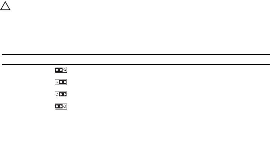
Table 4. System Board Jumper Settings
Jumper Setting Description
PWRD_EN
(default)
The password feature is enabled.
The password feature is disabled.
NVRAM_CLR
(default)
The configuration settings are retained at system boot.
The configuration settings are cleared at the next system boot.
(If the configuration settings become corrupted to the point
where the system does not boot, install the jumper and boot
the system. Remove the jumper before restoring the
configuration information.)
65
System Board Connectors
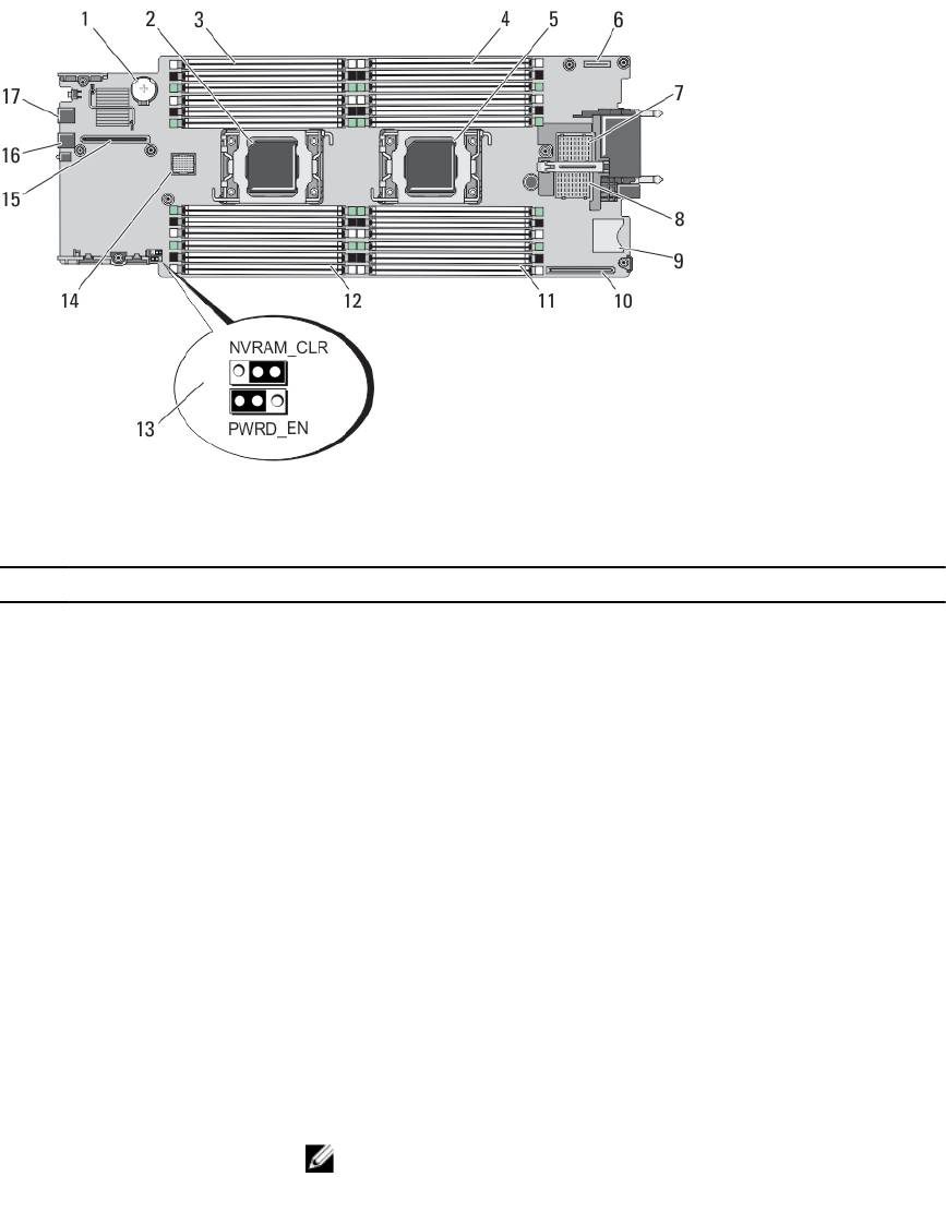
Figure 25. System Board Connectors
Table 5. System Board Connectors
Item Connector Description
1 BATTERY Connector for the 3.0 V coin cell battery
2 CPU2 Processor socket 2
3 B3, B7, B11, B4, B8, B12 Memory module sockets (for processor 2)
4 A1, A5, A9, A2, A6, A10 Memory module sockets (for processor 1)
5 CPU1 Processor socket 1
6 MANAGEMENT RISER Management riser card connector
7 MEZZ1_FAB_C PCIe Mezzanine card connector for Fabric C
8 MEZZ2_FAB_B PCIe Mezzanine card connector for Fabric B
9 vFLASH SD vFlash card connector
10 NETWORK DAUGHTER
Network daughter card connector
CARD
11 A3, A7, A11, A4, A8, A12 Memory module sockets (for processor 1)
12 B1, B5, B9, B2, B6, B10 Memory module sockets (for processor 2)
13 PWRD_EN, NVRAM_CLR
System configuration jumpers
NOTE: Access requires removal of system board.
14 HD_BP Hard-drive/SSD backplane connector
66
Item Connector Description
15 STORAGE PCIe extender card/storage controller card connector
16 USB2 USB connector
17 USB1 USB connector
Disabling A Forgotten Password
The server modules software security features include a system password and a setup password. The password jumper
enables these password features or disables them, and clears any password(s) currently in use.
CAUTION: Many repairs may only be done by a certified service technician. You should only perform
troubleshooting and simple repairs as authorized in your product documentation, or as directed by the online or
telephone service and support team. Damage due to servicing that is not authorized by Dell is not covered by your
warranty. Read and follow the safety instructions that came with the product.
1. Remove the server module from the enclosure.
2. Open the server module.
3. Remove the system board to gain access to the jumpers.
4. Relocate the jumper plug to disable the password feature.
5. Reinstall the system board.
6. Close the server module.
7. Install the server module in the enclosure.
When the server module is on, the power-on indicator is solid green. Allow the server module to finish booting.
The existing passwords are not disabled (erased) until the system boots with the password removed. However,
before you assign a new system and/or setup password, you must reinstall the password jumper.
NOTE: If you assign a new system and/or setup password with the jumper removed, the system disables the
new password(s) the next time it boots.
8. Remove the server module from the enclosure.
9. Open the server module.
10. Remove the system board to gain access to the jumpers.
11. Relocate the jumper plug to enable the password feature.
12. Reinstall the system board.
13. Close the server module.
14. Install the server module in the enclosure.
15. Assign a new system and/or setup password.
67
68
7
Technical Specifications
Processor
Processor type One or two Intel Xeon processor E5-2600 product family
Memory
Architecture 1600 MT/s, 1333 MT/s, 1066 MT/s, or 800 MT/s DDR3 and
LV-DDR3 DIMMs
Memory module sockets Twenty-four 240-pin
Memory module capacities
RDIMMs 2 GB (single-rank), 4 GB (single- and dual-rank), 8 GB
(dual-rank), 16 GB (dual-rank), and 32 GB (quad-rank)
UDIMMs 2 GB (single-rank) and 4 GB (dual-rank)
LRDIMMs 32 GB (quad-rank)
Minimum RAM 2 GB (single processor configuration)
Maximum RAM 768 GB (with 32 GB LRDIMMs)
Drives
Hard drives Up to two 2.5-inch, hot-swappable SAS/SATA hard drives
or two 2.5-inch, hot-swappable SAS/SATA/PCIe SSDs
Optical drive External optional USB DVD
NOTE: DVD devices are data only.
Flash drive
Internal optional USB
Internal optional SD card
Optional vFlash card (with integrated iDRAC7 Enterprise)
Connectors
Front
USB Two 4-pin, USB 2.0-compliant
Internal
SD
Two internal SD cards dedicated for the hypervisor
One dedicated for future vFlash support
69
PCIe mezzanine cards
PCIe Mezzanine card slots Two PCIe x8 Gen 2 slots supporting dual-port PCIe
mezzanine cards
Video
Video type Matrox G200 integrated with iDRAC
Video memory MB shared with iDRAC application memory
Battery
NVRAM backup battery CR 2032 3.0 V Lithium coin cell
Environmental
NOTE: For additional information about environmental measurements for specific system configurations, see
dell.com/environmental_datasheets.
Storage temperature –40 °C to 65 °C (–40 °F to 149 °F) with a maximum
temperature gradation of 20 °C per hour.
Standard operating temperature Continuous operation: 10 °C to 35 °C at 10% to 80%
relative humidity (RH), with 26 °C max dew point. De-rate
maximum allowable dry bulb temperature at 1 °C per 300
m above 900 m (1 °F per 550 ft).
Expanded operating temperature
NOTE: When operating in the expanded temperature
range, system performance may be impacted.
NOTE: When operating in the expanded temperature
range, ambient temperature warnings may be
reported on the LCD and in the System Event Log.
≤ 10% of annual operating hours 5 °C to 40 °C at 5% to 85% RH with 26 °C dew point.
NOTE: Outside the standard operating temperature
(10 °C to 35 °C), the system can operate down to 5 °C
or up to 40 °C for a maximum of 10% of its annual
operating hours.
For temperatures between 35 °C and 40 °C, de-rate
maximum allowable dry bulb temperature by 1 °C per 175
m above 950 m (1 °F per 319 ft).
≤ 1% of annual operating hours –5 °C to 45 °C at 5% to 90% RH with 26 °C dew point.
NOTE: Outside the standard operating temperature
(10 °C to 35 °C), the system can operate down to –5
°C or up to 45 °C for a maximum of 1% of its annual
operating hours.
70

Environmental
For temperatures between 40 °C and 45 °C, de-rate
maximum allowable dry bulb temperature by 1 °C per 125
m above 950 m (1 °F per 228 ft).
Expanded operating temperature restriction
• Do not perform a cold startup below 5 °C.
• Maximum 95 W processor is supported.
• The following do not support the expanded
operating temperature range:
– PCIe SSDs
– LRDIMMs
– Dell PowerEdge RAID Controller (PERC)
H710/H710P cards (in dual-processor
configurations)
• When populating the server module slots in the
PowerEdge VRTX enclosure with only
PowerEdge M620 server modules:
– Install only 97 mm wide heat sink(s).
– Dual-processor server modules with
PERC H310 cards cannot be mixed with
single-processor server modules.
– If you install a server module with two
processors and a PERC H310 card in the
PowerEdge VRTX enclosure, all server
module slots in the enclosure must have
PowerEdge M620 server modules with
the same configuration (PowerEdge
M620 server modules with two
processors and a PERC H310 card).
However, vacant server module slots in
the enclosure can be installed with
server module blanks.
71
72

8
System Messages
LCD Status Messages
The LCD messages consist of brief text messages that refer to events recorded in the System Event Log (SEL). For
information on the SEL and configuring system management settings, see the systems management software
documentation.
Viewing LCD Messages
If a system error occurs, the LCD screen will turn amber. Press the Select button to view the list of errors or status
messages. Use the left and right buttons to highlight an error number, and press Select to view the error.
Removing LCD Messages
For faults associated with sensors, such as temperature, voltage, fans, and so on, the LCD message is automatically
removed when that sensor returns to a normal state. For other faults, you must take action to remove the message from
the display:
• Clear the SEL — You can perform this task remotely, but you will lose the event history for the system.
• Power cycle — Turn off the system and disconnect it from the electrical outlet; wait approximately 10 seconds,
reconnect the power cable, and restart the system.
System Error Messages
System messages appear on the monitor to notify you of a possible problem with the system. These messages refer to
events recorded in the System Event Log (SEL). For information on the SEL and configuring system management settings,
see the systems management software documentation.
Some messages are also displayed in abbreviated form on the system's LCD, if the system includes that feature.
NOTE: The LCD error messages listed here are displayed in the simple format. See Setup Menu to select the format
in which the messages are displayed.
NOTE: If you receive a system message not listed here, check the documentation for the application that was
running when the message was displayed or the operating system's documentation for an explanation of the
message and recommended action.
NOTE: In some messages, a particular system component is identified by name (“<name>”), component number
(“<number>”), or location (“bay”).
Error Code
Message Information
AMP0300
Message The system board <
name
> current is less than the lower warning
threshold.
73

Error Code Message Information
Details System board <
name
> current is outside of the optimum range.
Action
1. Review system power policy.
2. Check system logs for power related failures.
3. Review system configuration changes.
4. If the issue persists, see Getting Help.
AMP0301
Message The system board <
name
> current is less than the lower warning
threshold.
LCD Message System board <
name
> current is outside of range.
Details System board <
name
> current is outside of the optimum range.
Action
1. Review system power policy.
2. Check system logs for power related failures.
3. Review system configuration changes.
4. If the issue persists, see Getting Help.
AMP0302
Message The system board <
name
> current is greater than the upper warning
threshold.
Details System board <
name
> current is outside of the optimum range.
Action
1. Review system power policy.
2. Check system logs for power related failures.
3. Review system configuration changes.
4. If the issue persists, see Getting Help.
AMP0303
Message The system board <
name
> current is greater than the upper critical
threshold.
LCD Message System board <
name
> current is outside of range.
Details System board <
name
> current is outside of the optimum range.
Action
1. Review system power policy.
2. Check system logs for power related failures.
3. Review system configuration changes.
4. If the issue persists, see Getting Help.
AMP0304
Message The system board <
name
> current is outside of range.
74

Error Code Message Information
LCD Message System board <
name
> current is outside of range.
Details System board <
name
> current is outside of the optimum range.
Action
1. Review system power policy.
2. Check system logs for power related failures.
3. Review system configuration changes.
4. If the issue persists, see Getting Help.
AMP0306
Message Disk drive bay <
name
> current is less than the lower warning
threshold.
Details Disk drive bay <
name
> current is outside of the optimum range.
Action
1. Review system power policy.
2. Check system logs for power related failures.
3. Review system configuration changes.
4. If the issue persists, see Getting Help.
AMP0307
Message Disk drive bay <
name
> current is less than the lower critical
threshold.
LCD Message Disk drive bay <
name
> current is outside of range.
Details Disk drive bay <
name
> current is outside of the optimum range.
Action
1. Review system power policy.
2. Check system logs for power related failures.
3. Review system configuration changes.
4. If the issue persists, see Getting Help.
AMP0308
Message Disk drive bay <
name
> current is greater than the upper warning
threshold.
Details Disk drive bay <
name
> current is outside of the optimum range.
Action
1. Review system power policy.
2. Check system logs for power related failures.
3. Review system configuration changes.
4. If the issue persists, see Getting Help.
75

Error Code Message Information
AMP0309
Message Disk drive bay <
name
> current is greater than the upper critical
threshold.
LCD Message Disk drive bay <
name
> current is outside of range.
Details Disk drive bay <
name
> current is outside of the optimum range.
Action
1. Review system power policy.
2. Check system logs for power related failures.
3. Review system configuration changes.
4. If the issue persists, see Getting Help.
AMP0310
Message Disk drive bay <
name
> current is outside of range.
LCD Message Disk drive bay <
name
> current is outside of range.
Details Disk drive bay <
name
> current is outside of the optimum range.
Action
1. Review system power policy.
2. Check system logs for power related failures.
3. Review system configuration changes.
4. If the issue persists, see Getting Help.
AMP0312
Message System level current is less than the lower warning threshold.
Details System level current is outside of the optimum range.
Action
1. Review system power policy.
2. Check system logs for power related failures.
3. Review system configuration changes.
4. If the issue persists, see Getting Help.
AMP0313
Message System level current is less than the lower warning threshold.
LCD Message System level current is outside of range.
Details System level current is outside of the optimum range.
Action
1. Review system power policy.
2. Check system logs for power related failures.
3. Review system configuration changes.
4. If the issue persists, see Getting Help.
76

Error Code Message Information
AMP0314
Message System level current is greater than the upper warning threshold.
Details System level current is outside of the optimum range.
Action
1. Review system power policy.
2. Check system logs for power related failures.
3. Review system configuration changes.
4. If the issue persists, see Getting Help.
AMP0315
Message System level current is greater than the upper critical threshold.
LCD Message System level current is outside of range.
Details System level current is outside of the optimum range.
Action
1. Review system power policy.
2. Check system logs for power related failures.
3. Review system configuration changes.
4. If the issue persists, see Getting Help.
AMP0316
Message System level current is outside of range.
LCD Message System level current is outside of range.
Details System level current is outside of the optimum range.
Action
1. Review system power policy.
2. Check system logs for power related failures.
3. Review system configuration changes.
4. If the issue persists, see Getting Help.
AMP0318
Message Chassis power level current is less than the lower warning threshold.
Details Chassis power level current is outside of the optimum range.
Action
1. Review system power policy.
2. Check system logs for power related failures.
3. Review system configuration changes.
4. If the issue persists, see Getting Help.
AMP0319
Message Chassis power level current is less than the lower critical threshold
Details Chassis power level current is outside of the optimum range.
77

Error Code Message Information
Action
1. Review system power policy.
2. Check system logs for power related failures.
3. Review system configuration changes.
4. If the issue persists, see Getting Help.
AMP0320
Message Chassis power level current is greater than the upper warning
threshold.
Details Chassis power level current is outside of the optimum range.
Action
1. Review system power policy.
2. Check system logs for power related failures.
3. Review system configuration changes.
4. If the issue persists, see Getting Help.
AMP0321
Message Chassis power level current is greater than the upper critical
threshold.
Details Chassis power level current is outside of the optimum range.
Action
1. Review system power policy.
2. Check system logs for power related failures.
3. Review system configuration changes.
4. If the issue persists, see Getting Help.
AMP0322
Message Chassis power level current is outside of range.
Details Chassis power level current is outside of the optimum range.
Action
1. Review system power policy.
2. Check system logs for power related failures.
3. Review system configuration changes.
4. If the issue persists, see Getting Help.
ASR0000
Message The watchdog timer expired.
Details The operating system or an application failed to communicate within
the time-out period.
Action Check the operating system, application, hardware, and system event
log for exception events.
78
Error Code Message Information
ASR0001
Message The watchdog timer reset the system.
Details The operating system or an application failed to communicate within
the time-out period. The system was reset.
Action Check the operating system, application, hardware, and system event
log for exception events.
ASR0002
Message The watchdog timer powered off the system.
Details The operating system or an application failed to communicate within
the time-out period. The system was shut down.
Action Check the operating system, application, hardware, and system event
log for exception events.
ASR0003
Message The watchdog timer power cycled the system.
Details The operating system or an application failed to communicate within
the time-out period. The system was power-cycled.
Action Check the operating system, application, hardware, and system event
log for exception events.
ASR0008
Message The watchdog timer interrupt was initiated.
Details The operating system or an application failed to communicate within
the time-out period. No action was taken.
Action Check the operating system, application, hardware, and system event
log for exception events.
ASR0100
Message The BIOS watchdog timer reset the system.
Details The operating system or an application failed to communicate within
the time-out period. The system was reset.
Action Check the operating system, application, hardware, and system event
log for exception events.
ASR0101
Message The OS watchdog timer reset the system.
Details The operating system or an application failed to communicate within
the time-out period. The system was reset.
Action Check the operating system, application, hardware, and system event
log for exception events.
ASR0102
Message The OS watchdog timer shutdown the system.
79
Error Code Message Information
Details The operating system or an application failed to communicate within
the time-out period. The system was shutdown.
Action Check the operating system, application, hardware, and system event
log for exception events.
ASR0103
Message The OS watchdog timer powered down the system.
Details The operating system or an application failed to communicate within
the time-out period. The system was powered down.
Action Check the operating system, application, hardware, and system event
log for exception events.
ASR0104
Message The OS watchdog timer power-cycled the system.
Details The operating system or an application failed to communicate within
the time-out period. The system was power-cycled.
Action Check the operating system, application, hardware, and system event
log for exception events.
ASR0105
Message The operating system watchdog timer powered off the system.
Details The operating system or an application failed to communicate within
the time-out period. The system was powered off.
Action Check the operating system, application, hardware, and system event
log for exception events.
ASR0106
Message The watchdog timer expired.
Details The operating system or an application failed to communicate within
the time-out period.
Action Check the operating system, application, hardware, and system event
log for exception events.
ASR0107
Message The watchdog timer pre-timeout interrupt was initiated.
Details The operating system or an application failed to communicate within
the time-out period.
Action Check the operating system, application, hardware, and system event
log for exception events.
BAT0000
Message The system board battery is low.
80
