Dell PowerEdge VRTX – страница 2
Инструкция к Компьютеру Dell PowerEdge VRTX
Оглавление

4. In the System Security screen, verify that Password Status is Unlocked.
5. Select System Password , enter your system password, and press <Enter> or <Tab>.
Use the following guidelines to assign the system password:
– A password can have up to 32 characters.
– The password can contain the numbers 0 through 9.
– Only lower case letters are valid, upper case letters are not allowed.
– The following special characters are allowed: space, (”), (+), (,), (-), (.), (/), (;), ([), (\), (]), (`).
A message prompts you to re-enter the system password.
6. Re-enter the system password that you entered earlier and click OK.
7. Select Setup Password, enter your system password and press <Enter> or <Tab>.
A message prompts you to re-enter the setup password.
8. Re-enter the setup password that you entered earlier and click OK.
9. Press <Esc> to save the changes.
NOTE: Password protection does not take effect until the system reboots.
Using Your System Password To Secure Your System
NOTE: If you have assigned a setup password, the system accepts your setup password as an alternate system
password.
1. Turn on or reboot your system.
2. Type your password and press <Enter>.
When Password Status is Locked, type the password and press <Enter> when prompted at reboot.
If an incorrect system password is entered, the system displays a message and prompts you to re-enter your password.
You have three attempts to enter the correct password. After the third unsuccessful attempt, the system displays an
error message that the system has halted and must be powered down.
Even after you shut down and restart the system, the error message is displayed until the correct password is entered.
NOTE: You can use the Password Status option in conjunction with the System Password and Setup Password
options to protect your system from unauthorized changes.
Deleting Or Changing An Existing System And/Or Setup Password
Ensure that the Password jumper is set to enabled and the Password Status is Unlocked before attempting to delete or
change the existing System and/or Setup password. You cannot delete or change an existing System or Setup password
if the Password Status is Locked.
To delete or change the existing System and/or Setup password:
1. To enter System Setup, press <F2> immediately after a power-on or reboot.
2. In the System Setup Main Menu, select System BIOS and press <Enter>.
The System BIOS screen is displayed.
3. In the System BIOS Screen, select System Security and press <Enter>.
The System Security screen is displayed.
4. In the System Security screen, verify that Password Status is Unlocked.
21

5. Select System Password, alter or delete the existing system password and press <Enter> or <Tab>.
6. Select Setup Password, alter or delete the existing setup password and press <Enter> or <Tab>.
NOTE: If you change the System and/or Setup password a message prompts you to re-enter the new
password. If you delete the System and/or Setup password, a message prompts you to confirm the deletion.
7. Press <Esc> to save the changes.
NOTE: You can disable password security while logging on to the system. To disable the password security, turn on
or reboot your system, type your password and press <Ctrl><Enter>.
Operating With A Setup Password Enabled
If Setup Password is Enabled, enter the correct setup password before modifying most of the System Setup options.
If you do not enter the correct password in three attempts, the system displays the message
Incorrect Password! Number of unsuccessful password attempts: <x> System
Halted! Must power down.
Even after you shut down and restart the system, the error message is displayed until the correct password is entered.
The following options are exceptions:
• If System Password is not Enabled and is not locked through the Password Status option, you can assign a
system password.
• You cannot disable or change an existing system password.
NOTE: You can use the Password Status option in conjunction with the Setup Password option to protect the
system password from unauthorized changes.
Entering The UEFI Boot Manager
NOTE: Operating systems must be 64-bit UEFI-compatible (for example, Microsoft Windows Server 2008 x64
version) to be installed from the UEFI boot mode. DOS and 32-bit operating systems can only be installed from the
BIOS boot mode.
The Boot Manager enables you to:
• Add, delete, and arrange boot options
• Access System Setup and BIOS-level boot options without rebooting
To enter the Boot Manager:
1. Turn on or restart your system.
2. Press <F11> after you see the following message:
<F11> = UEFI Boot Manager
If your operating system begins to load before you press <F11>, allow the system to finish booting, and then restart
your system and try again.
Using The Boot Manager Navigation Keys
Key
Description
Up arrow Moves to the previous field.
22

Key Description
Down arrow Moves to the next field.
<Enter> Allows you to type in a value in the selected field (if applicable) or follow the link in the field.
Spacebar Expands or collapses a drop-down list, if applicable.
<Esc> Moves to the previous page till you view the main screen. Pressing <Esc> in the main screen
exits System Setup. A message prompts you to save any unsaved changes.
<F1> Displays the System Setup help file.
NOTE: For most of the options, any changes that you make are recorded but do not take effect until you restart the
system.
Boot Manager Screen
Menu Item Description
Continue Normal
The system attempts to boot to devices starting with the first item in the boot order. If the boot
Boot
attempt fails, the system continues with the next item in the boot order until the boot is
successful or no more boot options are found.
BIOS Boot Menu Displays the list of available BIOS boot options (marked with asterisks). Select the boot option
you wish to use and press <Enter>.
UEFI Boot Menu Displays the list of available UEFI boot options (marked with asterisks). Select the boot option
you wish to use and press <Enter>. The UEFI Boot Menu enables you to Add Boot Option,
Delete Boot Option, or Boot From File.
Driver Health Menu Displays a list of the drivers installed on the system and their health status.
Launch System Setup Enables you to access the System Setup.
System Utilities Enables you to access the BIOS Update File Explorer, run the Dell Diagnostics program, and
reboot the system.
UEFI Boot Menu
Menu Item Description
Boot From File Sets a one-time boot option not included in the boot option list.
Select UEFI Boot
Displays the list of available UEFI boot options (marked with asterisks), select the boot option
Option
you wish to use and press <Enter>.
Add Boot Option Adds a new boot option.
Delete Boot Option Deletes an existing boot option.
Embedded System Management
The Dell Lifecycle Controller provides advanced embedded systems management throughout the server’s lifecycle. The
Lifecycle Controller can be started during the boot sequence and can function independently of the operating system.
23

NOTE: Certain platform configurations may not support the full set of features provided by the Lifecycle Controller.
For more information about setting up the Lifecycle Controller, configuring hardware and firmware, and deploying the
operating system, see the Lifecycle Controller documentation at dell.com/support/manuals.
iDRAC Settings Utility
The iDRAC Settings utility is an interface to setup and configure the iDRAC parameters using UEFI. You can enable or
disable various iDRAC parameters using the iDRAC7 Settings Utility, for example:
NOTE: Some of the features mentioned in the list may require the iDRAC7 Enterprise License upgrade.
• Configure, enable, or disable the iDRAC local area network through the dedicated iDRAC Enterprise card port or
the embedded NIC
• Enable or disable IPMI over LAN
• Enable a LAN Platform Event Trap (PET) destination
• Attach or detach the Virtual Media devices
For more information on using iDRAC7, see the iDRAC7 User's Guide, at dell.com/supoort/manuals.
Entering The iDRAC Settings Utility
1. Turn on or restart the managed system.
2. Press <F2> during Power-on Self-test (POST).
3. In the System Setup Main Menu page, click iDRAC Settings.
The iDRAC Settings page is displayed.
24

3
Installing Server Module Components
Recommended Tools
You may need the following items to perform the procedures in this section:
• #1 and #2 Phillips screwdrivers
• T8 and T10 Torx drivers
• Wrist grounding strap
Installing And Removing A Server Module
NOTE: Server modules that are specifically configured for the PowerEdge VRTX enclosure, can be identified by a
label marked PCIe on the server module.
NOTE: Ensure that you have downloaded the latest BIOS on the server module(s) from dell.com/support.
Removing A Server Module
1. Remove the front bezel.
2. Power down the server module using the operating system commands or the CMC, and ensure that the server
module's power is off.
When a server module is powered off, its front-panel power indicator is off.
3. Press the release button on the server module handle.
4. Pull out the server module handle to unlock the server module from the enclosure.
CAUTION: If you are permanently removing the server module, install a server module blank(s). Operating the
system for extended periods of time without a server module blank installed can cause the enclosure to
overheat.
5. Slide the server module out of the enclosure.
CAUTION: To protect the I/O connector pins, install the I/O connector covers any time a server module is
removed from the enclosure.
6. Install the I/O connector cover over the I/O connector.
25
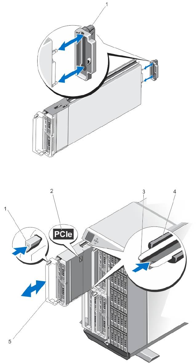
Figure 4. Removing and Installing the I/O Connector Cover
1. I/O connector cover
Figure 5. Removing and Installing a Server Module
26

1. release button
3. guide rail on server module (or server module
blank)
2. PCIe label on server module
4. guide rail on enclosure
NOTE: This label indicates that the
server module is configured specifically
5. server module handle
for the VRTX enclosure.
Installing A Server Module
1. If you are installing a new server module, remove the plastic cover from the I/O connector(s) and save for future
use.
2. Orient the server module so that the module handle is on the left side of the server module.
3. Slide the server module into the enclosure until the module release handle engages and locks the server module in
place.
4. Reinstall the front bezel.
Opening And Closing The Server Module
Opening The Server Module
CAUTION: Many repairs may only be done by a certified service technician. You should only perform
troubleshooting and simple repairs as authorized in your product documentation, or as directed by the online or
telephone service and support team. Damage due to servicing that is not authorized by Dell is not covered by your
warranty. Read and follow the safety instructions that came with the product.
NOTE: It is recommended that you always use a static mat and static strap while working on components in the
interior of the system.
1. Remove the server module from the enclosure.
2. Install the I/O connector cover.
3. Press the release button and slide the cover toward the back of the server module.
4. Carefully lift the cover away from the server module.
27

Figure 6. Opening and Closing the Server Module
1. I/O connector cover
2. server module cover
3. release button
4. cover alignment pins and notches
Closing The Server Module
1. Ensure that no tools or parts are left inside the server module.
2. Align the notches in the edges of the chassis with the cover alignment pins on the inner sides of the cover.
3. Lower the cover onto the chassis.
4. Slide the cover until it clicks into position.
A properly seated cover is flush with the surface of the chassis.
28
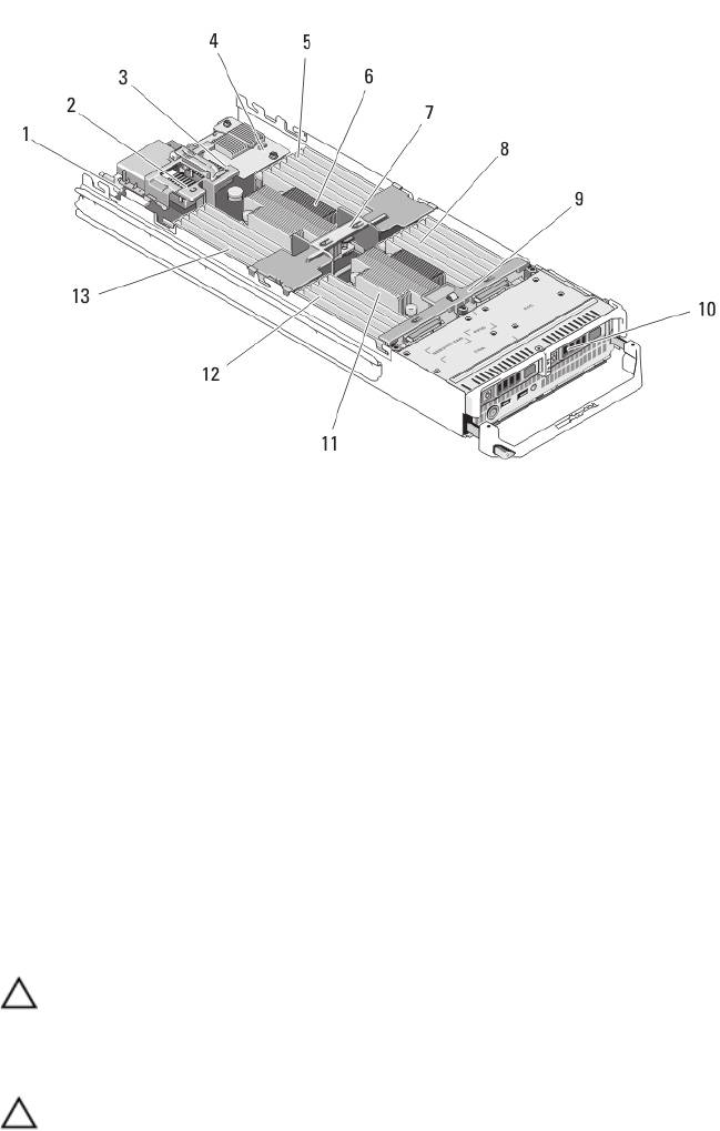
Inside The Server Module
Figure 7. Inside the Server Module
1. management riser card
8. memory modules (for processor 2)
2. mezzanine card 1/PCIe mezzanine card 1 - Fabric C
9. hard-drive/SSD backplane
3. mezzanine card 2/PCIe mezzanine card 2 - Fabric B
10. hard drives/SSDs (2)
4. network daughter card
11. processor 2 and heat sink
5. memory modules (for processor 1)
12. memory modules (for processor 2)
6. processor 1 and heat sink
13. memory modules (for processor 1)
7. cooling shroud
Cooling Shroud
The cooling shroud covers the memory modules and directs air flow in the system.
Removing The Cooling Shroud
CAUTION: Many repairs may only be done by a certified service technician. You should only perform
troubleshooting and simple repairs as authorized in your product documentation, or as directed by the online or
telephone service and support team. Damage due to servicing that is not authorized by Dell is not covered by your
warranty. Read and follow the safety instructions that came with the product.
CAUTION: Never operate your system with the cooling shroud removed. The system may get overheated quickly,
resulting in shutdown and loss of data.
1. Remove the server module from the enclosure.
2. Open the server module.
29
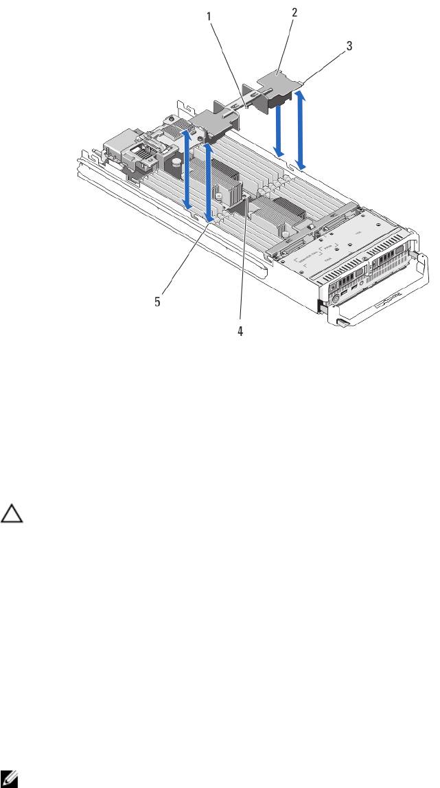
3. Hold the cooling shroud at both ends near the server module chassis and lift it up and away from the server
module.
Figure 8. Installing and Removing a Cooling Shroud
1. pins under the cooling shroud (2)
4. holes on the heat sink (2)
2. cooling shroud
5. slots on the chassis (4)
3. tabs (4)
Installing The Cooling Shroud
CAUTION: Many repairs may only be done by a certified service technician. You should only perform
troubleshooting and simple repairs as authorized in your product documentation, or as directed by the online or
telephone service and support team. Damage due to servicing that is not authorized by Dell is not covered by your
warranty. Read and follow the safety instructions that came with the product.
1. Position the tabs below the shroud to align with the holes on the heat sink installed on processor socket CPU1.
2. Lower the cooling shroud into the system until the tabs on the sides of the shroud engage with the slots on the
server module chassis and the pins under the shroud engage with the holes on the heat sink.
3. Close the server module.
4. Install the server module in the enclosure.
System Memory
Your system supports DDR3 unbuffered ECC DIMMs (UDIMM ECC) and registered DIMMs (RDIMMs). It supports DDR3
and DDR3L voltage specifications.
NOTE: MT/s indicates DIMM speed in MegaTransfers per second.
30
Memory bus operating frequency can be 1600 MT/s, 1333 MT/s, 1066 MT/s, or 800 MT/s depending on:
• DIMM type (UDIMM, RDIMM, or LRDIMM)
• DIMM configuration (number of ranks)
• maximum frequency of the DIMMs
• number of DIMMs populated per channel
• DIMM operating voltage
• system profile selected (for example, Performance Optimized, Custom, or Dense Configuration Optimized)
• maximum supported DIMM frequency of the processors
The system contains 24 memory sockets split into two sets of 12 sockets, one set per processor. Each 12-socket set is
organized into four channels. In each channel, the release levers of the first socket are marked white, the second socket
black, and the third socket green.
NOTE: DIMMs in sockets A1 to A12 are assigned to processor 1 and DIMMs in sockets B1 to B12 are assigned to
processor 2.
The following table shows the memory populations and operating frequencies for the supported configurations.
DIMM Type DIMMs Populated/
Operating Frequency (in MT/s) Maximum DIMM Rank/
Channel
Channel
1.5 V 1.35 V
UDIMM ECC 1 1333, 1066, and 800 1333, 1066, and 800 Dual rank
2 1333, 1066, and 800 1333, 1066, and 800 Dual rank
RDIMM 1
1600, 1333, 1066, and 800
1333, 1066, and 800
Dual rank
1333, 1066, and 800
1066 and 800
Quad rank
2
1600, 1333, 1066, and 800
1333, 1066, and 800
Dual rank
1066 and 800
1066 and 800
Quad rank
3 1333, 1066, and 800 1066 and 800 Dual rank
LRDIMM 1 1333 and 1066 1333 and 1066 Quad rank
2 1333 and 1066 1333 and 1066 Quad rank
3 1066 1066 Quad rank
31
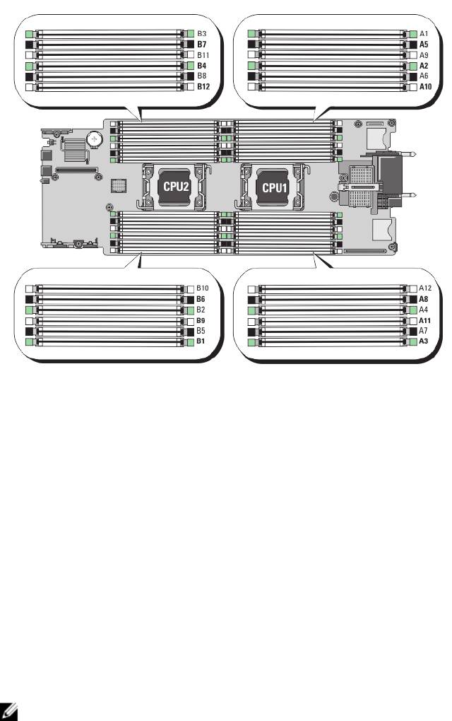
Figure 9. Memory Socket Locations
Memory channels are organized as follows:
Processor 1 channel 0: memory sockets A2, A6, and A10
channel 1: memory sockets A1, A5, and A9
channel 2: memory sockets A4, A8, and A12
channel 3: memory sockets A3, A7, and A11
Processor 2 channel 0: memory sockets B2, B6, and B10
channel 1: memory sockets B1, B5, and B9
channel 2: memory sockets B4, B8, and B12
channel 3: memory sockets B3, B7, and B11
General Memory Module Installation Guidelines
NOTE: Memory configurations that fail to observe these guidelines can prevent your system from starting and
producing any video output, hanging during memory configuration, or operating with reduced memory.
This system supports Flexible Memory Configuration, enabling the system to be configured and run in any valid chipset
architectural configuration. The following are the recommended guidelines for best performance:
• UDIMMs, RDIMMs, and LRDIMMs must not be mixed.
• x4 and x8 DRAM based DIMMs can be mixed. For more information, see Mode-Specific Guidelines.
• A maximum of two UDIMMs can be populated in a channel.
32

• Up to three LRDIMMs can be populated regardless of rank count.
• Up to two quad-rank RDIMMs and up to three dual- or single-rank RDIMMs can be populated per channel.
When a quad-rank RDIMM is populated in the first slot with white release levers, the third DIMM slot in the
channel with green release levers cannot be populated.
• Populate DIMM sockets only if a processor is installed. For single-processor systems, sockets A1 to A12 are
available. For dual-processor systems, sockets A1 to A12 and sockets B1 to B12 are available.
• Populate all sockets with white release tabs first, then black, and then green.
• Do not populate the third DIMM socket in a channel with green release tabs, if a quad-rank RDIMM is populated
in the first socket with white release tabs.
• Populate the sockets by highest rank count in the following order - first in sockets with white release levers,
then black, and then green. For example, if you want to mix quad-rank and dual-rank DIMMs, populate quad-
rank DIMMs in the sockets with white release tabs and dual-rank DIMMs in the sockets with black release tabs.
• In a dual-processor configuration, the memory configuration for each processor must be identical. For example,
if you populate socket A1 for processor 1, then populate socket B1 for processor 2, and so on.
• Memory modules of different sizes can be mixed provided that other memory population rules are followed (for
example, 2 GB and 4 GB memory modules can be mixed).
• Populate four DIMMs per processor (one DIMM per channel) at a time to maximize performance.
• If memory modules with different speeds are installed, they will operate at the speed of the slowest installed
memory module(s) or slower depending on system DIMM configuration.
• Populate DIMMs based on the following processor— heat sink configurations.
Table 1. Processor—Heat Sink Configuration
Processor
Processor
Heat Sink Number of DIMMs
Configuration
Type (in
Watts)
Maximum System Capacity Reliability, Availability, and
Serviceability (RAS) Features
Single processor up to 95 W 57 mm 12 12
Single processor 115 W or
77 mm 10 (Three DIMMs in
8 (Two DIMMs per channel)
130 W
channels 0 and 3 and two
DIMMs in channels 1 and 2)
Dual processor up to 95 W 57 mm 24 24
Dual processor 115 W or
77 mm 20 (Three DIMMs in
16 (Two DIMMs per channel)
130 W
channels 0 and 3 and two
DIMMs in channels 1 and 2)
NOTE: For optimal performance, your system may be configured with a larger heat sink than listed above.
Do not use any heat sink smaller than the configurations described above.
Mode-Specific Guidelines
Four memory channels are allocated to each processor. The allowable configurations depend on the memory mode
selected.
NOTE: x4 and x8 DRAM based DIMMs can be mixed providing support for RAS features. However, all guidelines for
specific RAS features must be followed. x4 DRAM based DIMMs retain Single Device Data Correction (SDDC) in
memory optimized (independent channel) mode. x8 DRAM based DIMMs require Advanced ECC mode to gain
SDDC.
The following sections provide additional slot population guidelines for each mode.
33

Advanced ECC (Lockstep)
Advanced ECC mode extends SDDC from x4 DRAM based DIMMs to both x4 and x8 DRAMs. This protects against single
DRAM chip failures during normal operation.
Memory installation guidelines:
• Memory modules must be identical in size, speed, and technology.
• DIMMs installed in memory sockets with white release tabs must be identical and similar rule applies for
sockets with black and green release tabs. This ensures that identical DIMMs are installed in matched pairs -
for example, A1 with A2, A3 with A4, A5 with A6, and so on.
NOTE: Advanced ECC with mirroring is not supported.
Memory Optimized (Independent Channel) Mode
This mode supports SDDC only for memory modules that use x4 device width and does not impose any specific slot
population requirements.
Memory Sparing
NOTE: To use memory sparing, this feature must be enabled in the System Setup.
In this mode, one rank per channel is reserved as a spare. If persistent correctable errors are detected on a rank, the
data from this rank is copied to the spare rank and the failed rank is disabled.
With memory sparing enabled, the system memory available to the operating system is reduced by one rank per
channel. For example, in a dual-processor configuration with sixteen 4 GB dual-rank DIMMs, the available system
memory is: 3/4 (ranks/channel) × 16 (DIMMs) × 4 GB = 48 GB, and not 16 (DIMMs) × 4 GB = 64 GB.
NOTE: Memory sparing does not offer protection against a multi-bit uncorrectable error.
NOTE: Both Advanced ECC/Lockstep and Optimizer modes support Memory Sparing.
Memory Mirroring
Memory Mirroring offers the strongest DIMM reliability mode compared to all other modes, providing improved
uncorrectable multi-bit failure protection. In a mirrored configuration, the total available system memory is one half of
the total installed physical memory. Half of the installed memory is used to mirror the active DIMMs. In the event of an
uncorrectable error, the system will switch over to the mirrored copy. This ensures SDDC and multi-bit protection.
Memory installation guidelines:
• Memory modules must be identical in size, speed, and technology.
• DIMMs installed in memory sockets with white release tabs must be identical and similar rule applies for
sockets with black and green release tabs. This ensures that identical DIMMs are installed in matched pairs -
for example, A1 with A2, A3 with A4, A5 with A6, and so on.
Sample Memory Configurations
The following tables show sample memory configurations that follow the appropriate memory guidelines stated in this
section.
NOTE: 16 GB quad-rank RDIMMs are not supported.
NOTE: 1R, 2R, and 4R in the following tables indicate single-, dual-, and quad-rank DIMMs respectively.
34
Table 2. Memory Configurations – Single Processor
System Capacity
DIMM Size (in
Number of
Organization and
DIMM Slot Population
(in GB)
GB)
DIMMs
Speed
2 2 1
1R x8, 1333 MT/s
A1
1R x8, 1600 MT/s
4 2 2
1R x8, 1333 MT/s
A1, A3
1R x8, 1600 MT/s
8 2 4
1R x8, 1333 MT/s
A1, A2, A3, A4
1R x8, 1600 MT/s
12 2 6
1R x8, 1333 MT/s
A1, A2, A3, A4, A5, A6
1R x8, 1600 MT/s
16 2 8 1R x8, 1333 MT/s A1, A2, A3, A4, A5, A6, A7, A8
16 4 4
2R x8, 1333 MT/s
A1, A2, A3, A4
2R x8, 1600 MT/s
24 2 12 1R x8, 1333 MT/s A1, A2, A3, A4, A5, A6, A7, A8, A9, A10,
A11, A12
24 4 6
2R x8, 1333 MT/s
A1, A2, A3, A4, A5, A6
2R x8, 1600 MT/s
48 4 12 2R x8, 1333 MT/s A1, A2, A3, A4, A5, A6, A7, A8, A9, A10,
A11, A12
48 8 6
2R x4, 1333 MT/s
A1, A2, A3, A4, A5, A6
2R x4, 1600 MT/s
96 8 12 2R x4, 1333 MT/s A1, A2, A3, A4, A5, A6, A7, A8, A9, A10,
A11, A12
96 16 6
2R x4, 1333 MT/s
A1, A2, A3, A4, A5, A6
2R x4, 1600 MT/s
128 16 8
2R x4, 1333 MT/s
A1, A2, A3, A4, A5, A6, A7, A8
2R x4, 1600 MT/s
144 16 and 8 10 2R x4, 1333 MT/s
A1, A2, A3, A4, A5, A6, A7, A8, A9, A11
NOTE: 16 GB DIMMs must be
installed in the slots numbered
A1, A2, A3, A4, A5, A6, A7, and A8
and 8 GB DIMMs must be
installed in slots A9 and A11.
256 32 8 4R x4, 1333 MT/s A1, A2, A3, A4, A5, A6, A7, A8
384 32 12 4R x4, 1333 MT/s
A1, A2, A3, A4, A5, A6, A7, A8, A9, A10,
(LRDIMMs only)
A11, A12
35
Table 3. Memory Configurations – Two Processors
System Capacity (in
DIMM Size (in
Number of
Organization and
DIMM Slot Population
GB)
GB)
DIMMs
Speed
16 2 8
1R x8, 1333 MT/s
A1, A2, A3, A4, B1, B2, B3, B4
1R x8, 1600 MT/s
32 2 16 1R x8, 1333 MT/s A1, A2, A3, A4, A5, A6, A7, A8,
B1, B2, B3, B4, B5, B6, B7, B8
32 4 8
2R x8, 1333 MT/s
A1, A2, A3, A4, B1, B2, B3, B4
2R x8, 1600 MT/s
64 4 16 2R x8, 1333 MT/s A1, A2, A3, A4, A5, A6, A7, A8,
B1, B2, B3, B4, B5, B6, B7, B8
64 8 8
2R x4, 1333 MT/s
A1, A2, A3, A4, B1, B2, B3, B4
2R x4, 1600 MT/s
96 4 24 2R x8, 1333 MT/s A1, A2, A3, A4, A5, A6, A7, A8,
A9, A10, A11, A12, B1, B2, B3,
B4, B5, B6, B7, B8, B9, B10,
B11, B12
96 8 12
2R x8, 1333 MT/s
A1, A2, A3, A4, A5, A6, B1, B2,
2R x8, 1600 MT/s
B3, B4, B5, B6
128 8 16 2R x4, 1333 MT/s A1, A2, A3, A4, A5, A6, A7, A8,
B1, B2, B3, B4, B5, B6, B7, B8
128 16 8
2R x4, 1333 MT/s
A1, A2, A3, A4, B1, B2, B3, B4
2R x4, 1600 MT/s
160 8 20 2R x4, 1333 MT/s A1, A2, A3, A4, A5, A6, A7, A8,
A9, A11, B1, B2, B3, B4, B5,
B6, B7, B8, B9, B11
160 16 and 8 12
2R x4, 1333 MT/s
A1, A2, A3, A4, A5, A6, B1, B2,
B3, B4, B5, B6
2R x4, 1600 MT/s
NOTE: 16 GB DIMMs
must be installed in the
slots numbered A1, A2,
A3, A4, B1, B2, B3, and B4
and 8 GB DIMMs must be
installed in slots A5, A6,
B5 and B6.
192 8 24 2R x4, 1333 MT/s A1, A2, A3, A4, A5, A6, A7, A8,
A9, A10, A11, A12, B1, B2, B3,
B4, B5, B6, B7, B8, B9, B10,
B11, B12
192 16 12
2R x4, 1333 MT/s
A1, A2, A3, A4, A5, A6, B1, B2,
2R x4, 1600 MT/s
B3, B4, B5, B6
256 16 16
2R x4, 1333 MT/s
A1, A2, A3, A4, A5, A6, A7, A8,
2R x4, 1600 MT/s
B1, B2, B3, B4, B5, B6, B7, B8
36
System Capacity (in
DIMM Size (in
Number of
Organization and
DIMM Slot Population
GB)
GB)
DIMMs
Speed
384 16 24 2R x4, 1333 MT/s A1, A2, A3, A4, A5, A6, A7, A8,
A9, A10, A11, A12, B1, B2, B3,
B4, B5, B6, B7, B8, B9, B10,
B11, B12
512 32 16 4R x4, 1333 MT/s A1, A2, A3, A4, A5, A6, A7, A8,
B1, B2, B3, B4, B5, B6, B7, B8
768 32 24 4R x4, 1333 MT/s
A1, A2, A3, A4, A5, A6, A7, A8,
(LRDIMMs only)
A9, A10, A11, A12, B1, B2, B3,
B4, B5, B6, B7, B8, B9, B10,
B11, B12
Removing Memory Modules
WARNING: The DIMMs are hot to touch for some time after the server module has been powered down. Allow
time for the DIMMs to cool before handling them. Handle the DIMMs by the card edges and avoid touching the
DIMM components.
CAUTION: Many repairs may only be done by a certified service technician. You should only perform
troubleshooting and simple repairs as authorized in your product documentation, or as directed by the online or
telephone service and support team. Damage due to servicing that is not authorized by Dell is not covered by your
warranty. Read and follow the safety instructions that came with the product.
CAUTION: To ensure proper system cooling, memory-module blanks must be installed in any memory socket that is
not occupied. Remove memory-module blanks only if you intend to install memory in those sockets.
CAUTION: If you are permanently removing a processor, you must install a socket protective cap and a processor/
DIMM blank in the vacant socket to ensure proper system cooling. The processor/DIMM blank covers the vacant
sockets for the DIMMs and the processor.
1. Remove the server module from the enclosure.
2. Open the server module.
3. Remove the cooling shroud.
4. Locate the memory module socket(s).
CAUTION: Handle each memory module only on either card edge, making sure not to touch the middle of the
memory module.
5. Press down and out on the ejectors on each end of the socket until the memory module pops out of the socket.
6. Install the cooling shroud.
7. Close the server module.
8. Install the server module in the enclosure.
37
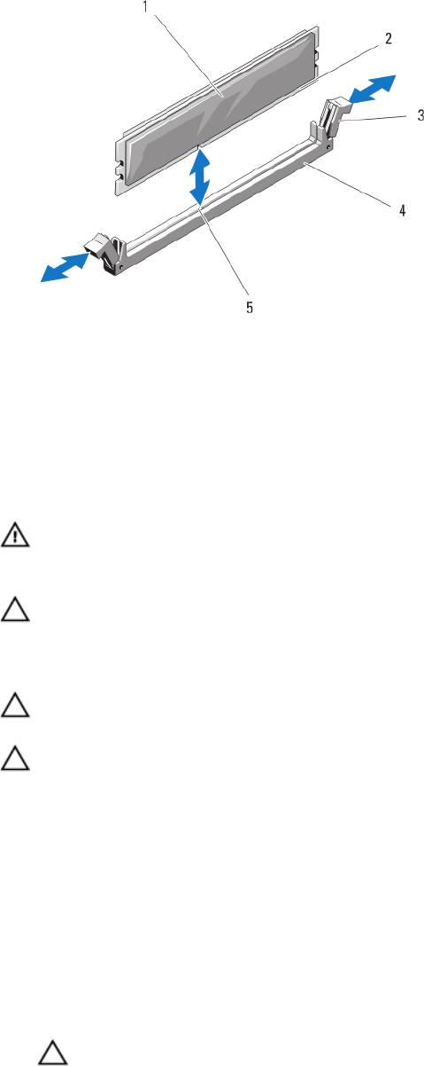
Figure 10. Installing and Removing a Memory Module or Memory Module Blank
1. memory module or memory blank
4. socket
2. edge connector
5. alignment key
3. ejectors (2)
Installing Memory Modules
WARNING: The memory modules are hot to the touch for some time after the system has been powered down.
Allow time for the memory modules to cool before handling them. Handle the memory modules by the card edges
and avoid touching the components on the memory module.
CAUTION: Many repairs may only be done by a certified service technician. You should only perform
troubleshooting and simple repairs as authorized in your product documentation, or as directed by the online or
telephone service and support team. Damage due to servicing that is not authorized by Dell is not covered by your
warranty. Read and follow the safety instructions that came with the product.
CAUTION: To ensure proper system cooling, memory-module blanks must be installed in any memory socket that is
not occupied. Remove memory-module blanks only if you intend to install memory in those sockets.
CAUTION: If you are permanently removing a processor, you must install a socket protective cap and a processor/
DIMM blank in the vacant socket to ensure proper system cooling. The processor/DIMM blank covers the vacant
sockets for the DIMMs and the processor.
1. Remove the server module from the enclosure.
2. Open the server module.
3. Remove the cooling shroud.
4. Locate the appropriate memory module socket(s).
5. Press the ejectors on the memory module socket down and out to allow the memory module to be inserted into the
socket.
If a memory module blank is installed in the socket, remove it. Retain removed memory-module blank(s) for future
use.
CAUTION: Handle each memory module only on either card edge, making sure not to touch the middle of the
memory module.
38

6. Align the memory module's edge connector with the alignment key on the memory module socket, and insert the
memory module in the socket.
NOTE: The memory module socket has an alignment key that allows you to install the memory module in the
socket in only one way.
7. Press down on the memory module with your thumbs to lock the memory module into the socket.
When the memory module is properly seated in the socket, the ejectors on the memory module socket align with
the ejectors on the other sockets that have memory modules installed.
8. Repeat step 5 through step 7 of this procedure to install the remaining memory modules.
9. Install the cooling shroud.
10. Close the server module.
11. Install the server module in the enclosure.
12. (Optional) Press <F2> to enter the System Setup, and check the System Memory setting.
The system should have already changed the value to reflect the newly installed memory.
13. If the value is incorrect, one or more of the memory modules may not be installed properly. Check to ensure that the
memory modules are firmly seated in their sockets.
14. Run the system memory test in the system diagnostics.
PCIe Mezzanine Cards
The server module supports Dell PCIe mezzanine cards. x8 PCIe Gen 2 cards are supported. No other mezzanine cards,
such as Ethernet, Fibre Channel, or InfiniBand are supported on server modules configured for the VRTX enclosure.
The PCIe mezzanine cards provide an interface between server modules and the PCIe switches in the enclosure.
NOTE: Single PCIe mezzanine card operation is not supported. Two PCIe mezzanine cards are required per server
module to support the PCIe expansion cards and PERC card-based shared storage on the enclosure.
NOTE: For proper operation, make sure that both PCIe mezzanine cards are set to Enabled in the system setup.
Removing A PCIe Mezzanine Card
CAUTION: Many repairs may only be done by a certified service technician. You should only perform
troubleshooting and simple repairs as authorized in your product documentation, or as directed by the online or
telephone service and support team. Damage due to servicing that is not authorized by Dell is not covered by your
warranty. Read and follow the safety instructions that came with the product.
1. Remove the server modulefrom the enclosure.
2. Open the server module.
3. Open the PCIe mezzanine card latch by pressing the ridged area on the latch with your thumb, and lifting the end of
the latch.
NOTE: Hold the PCIe mezzanine card by its edges only.
4. Lift the PCIe mezzanine card up and away from the system board.
5. Close the retention latch.
6. Close the server module.
7. Install the server modulein the enclosure.
39
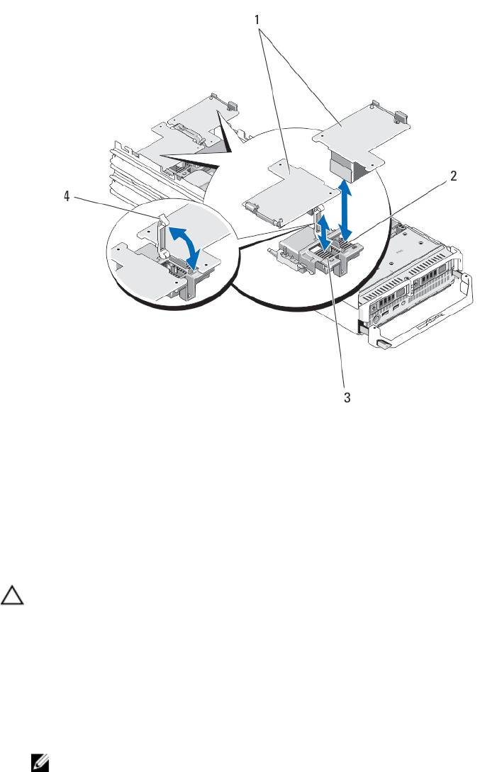
Figure 11. Removing and Installing a PCIe mezzanine Card
1. PCIe mezzanine cards (2)
2. Fabric B PCIe mezzanine card slot
3. Fabric C PCIe mezzanine card slot
4. retention latch
Installing A PCIe Mezzanine Card
CAUTION: Many repairs may only be done by a certified service technician. You should only perform
troubleshooting and simple repairs as authorized in your product documentation, or as directed by the online or
telephone service and support team. Damage due to servicing that is not authorized by Dell is not covered by your
warranty. Read and follow the safety instructions that came with the product.
1. Remove the server module from the enclosure.
2. Open the server module.
3. Open the retention latch by pressing the ridged area on the latch with your thumb and lifting the end of the latch.
4. If present, remove the connector cover from the PCIe Mezzanine card bay.
NOTE: Hold the PCIe Mezzanine card by its edges only.
5. PCIe Mezzanine cards are designed to fit in either card slot. Rotate the card to align the connector on the bottom of
the PCIe Mezzanine card with the corresponding socket on the system board.
6. Lower the card into place until it is fully seated and the plastic clip on the outer edge of the card fits over the side of
the server module chassis.
7. Close the retention latch to secure the PCIe Mezzanine card.
40
