Dell Precision 690: инструкция
Раздел: Бытовая, кухонная техника, электроника и оборудование
Тип: Компьютер
Инструкция к Компьютеру Dell Precision 690
Оглавление
- Примечания, символы внимания и предупреждения
- Содержание
- Поиск информации Возможные направления поиска Где искать
- Возможные направления поиска Где искать
- Возможные направления поиска Где искать
- Возможные направления поиска Где искать
- Установка компьютера 1 2
- 3
- Видеоплата для подключения одного и двух мониторов, с одним разъемом
- Видеоплата для подключения двух мониторов, с одним DVI- и одним VGA-разъемом Видеоплата для подключения двух мониторов, с двумя DVI-разъемами
- 4 5
- 6 О компьютере
- Вид спереди
- 6
- 13
- Вид сзади
- Разъемы на задней панели 4
- 13
- Вид изнутри
- Элементы системной платы
- 17
- Устройство Цвет Дополнительная информация, содержащаяся в руководстве пользователя
- Снятие крышки корпуса компьютера 1 2 3 4
- 5 6 7 8
- Подставка компьютера Установка подставки компьютера
- 9
- Снятие подставки компьютера
- Решение проблем Советы по устранению неполадок Несовместимость программного и аппаратного обеспечения
- Создание точки восстановления Восстановление предыдущего работоспособного состояния компьютера Отмена последнего восстановления системы
- Включение функции System Restore Использование последней работоспособной конфигурации Другие возможности решения конфликтов аппаратного и программного обеспечения Программа диагностики Dell Diagnostics Когда использовать программу Dell Diagnostics
- Запуск программы Dell Diagnostics с жесткого диска Запуск программы Dell Diagnostics с компакт-диска Drivers and Utilities
- Перед началом тестирования Звуковые коды Код Причина
- Код Причина
- Сообщения об ошибках Индикаторы диагностики Коды индикаторов диагностики перед выполнением теста POST Индикаторы диагностики
- Индикаторы диагностики
- Индикаторы диагностики Сигналы диагностических светодиодов во время процедуры POST Светодиоды Описание проблемы Варианты решения
- Светодиоды Описание проблемы Варианты решения
- Светодиоды Описание проблемы Варианты решения
- Светодиоды Описание проблемы Варианты решения
- Светодиоды Описание проблемы Варианты решения
- Часто задаваемые вопросы Как сделать... Решение Источник информации
- Как сделать... Решение Источник информации
- Индекс
- 270 Индекс
- Индекс 271

Dell Precision™ Workstation 690
Quick Reference Guide
Model DCD0
www.dell.com | support.dell.com

Notes, Notices, and Cautions
NOTE: A NOTE indicates important information that helps you make better use of your computer.
NOTICE: A NOTICE indicates either potential damage to hardware or loss of data and tells you how to avoid
the problem.
CAUTION: A CAUTION indicates a potential for property damage, personal injury, or death.
Abbreviations and Acronyms
For a complete list of abbreviations and acronyms, see Glossary in your
User’s Guide
.
®
®
If you purchased a Dell™ n Series computer, any references in this document to Microsoft
Windows
operating systems are not applicable.
____________________
Information in this document is subject to change without notice.
© 2006 Dell Inc. All rights reserved.
Reproduction in any manner whatsoever without the written permission of Dell Inc. is strictly forbidden.
Trademarks used in this text: Dell, the DELL logo and Dell Precision are trademarks of Dell Inc.; Intel, Xeon, and Pentium are registered
trademarks of Intel Corporation; Microsoft and Windows are registered trademarks of Microsoft Corporation.
Other trademarks and trade names may be used in this document to refer to either the entities claiming the marks and names or their products.
Dell Inc. disclaims any proprietary interest in trademarks and trade names other than its own.
Model DCD0
January 2006 P/N PD050 Rev. A00

Contents
Finding Information . . . . . . . . . . . . . . . . . . . . . . . . . . . . . . . . 5
Setting Up Your Computer
. . . . . . . . . . . . . . . . . . . . . . . . . . . . . 9
About Your Computer
. . . . . . . . . . . . . . . . . . . . . . . . . . . . . . . 14
Front View
. . . . . . . . . . . . . . . . . . . . . . . . . . . . . . . . . . 15
Back View
. . . . . . . . . . . . . . . . . . . . . . . . . . . . . . . . . . 18
Back Panel Connectors
. . . . . . . . . . . . . . . . . . . . . . . . . . . 19
Inside View
. . . . . . . . . . . . . . . . . . . . . . . . . . . . . . . . . 21
System Board Components
. . . . . . . . . . . . . . . . . . . . . . . . . 22
Locating Your User’s Guide
. . . . . . . . . . . . . . . . . . . . . . . . . . . 24
Removing the Computer Cover
. . . . . . . . . . . . . . . . . . . . . . . . . . 24
Computer Stand
. . . . . . . . . . . . . . . . . . . . . . . . . . . . . . . . . 27
Attaching the Computer Stand
. . . . . . . . . . . . . . . . . . . . . . . 27
Removing the Computer Stand
. . . . . . . . . . . . . . . . . . . . . . . 29
Caring for Your Computer
. . . . . . . . . . . . . . . . . . . . . . . . . . . . 29
Solving Problems
. . . . . . . . . . . . . . . . . . . . . . . . . . . . . . . . 29
Troubleshooting Tips
. . . . . . . . . . . . . . . . . . . . . . . . . . . . 29
Resolving Software and Hardware Incompatibilities
. . . . . . . . . . . 30
®
®
Using Microsoft
Windows
XP System Restore . . . . . . . . . . . . . 30
Using the Last Known Good Configuration
. . . . . . . . . . . . . . . . . 31
Dell Diagnostics
. . . . . . . . . . . . . . . . . . . . . . . . . . . . . . . 32
Before you start testing
. . . . . . . . . . . . . . . . . . . . . . . . . . . 33
Beep Codes
. . . . . . . . . . . . . . . . . . . . . . . . . . . . . . . . . . . . 33
Error Messages
. . . . . . . . . . . . . . . . . . . . . . . . . . . . . . . 35
Diagnostic Lights
. . . . . . . . . . . . . . . . . . . . . . . . . . . . . . . . . 35
Diagnostic Light Codes Before POST
. . . . . . . . . . . . . . . . . . . . 35
Diagnostic Light Codes During POST
. . . . . . . . . . . . . . . . . . . . 37
Frequently Asked Questions
. . . . . . . . . . . . . . . . . . . . . . . . . . . 42
Index . . . . . . . . . . . . . . . . . . . . . . . . . . . . . . . . . . . . . . . . . 43
Contents 3

4 Contents
Finding Information
NOTE: Some features or media may be optional and may not ship with your computer. Some features or media
may not be available in certain countries.
NOTE: Additional information may ship with your computer.
What Are You Looking For? Find It Here
• A diagnostic program for my computer
Drivers and Utilities CD (also known as Resource CD)
• Drivers for my computer
Documentation and
• My computer documentation
drivers are already
• My device documentation
installed on your
computer. You can use
• Desktop System Software (DSS)
the CD to reinstall drivers,
run the Dell Diagnostics
or access your
documentation. Readme
files may be included on
your CD to provide last-
minute updates about
technical changes to your computer or advanced technical-
reference material for technicians or experienced users.
NOTE: Drivers and documentation updates can be found
at support.dell.com.
• How to set up my computer
Quick Reference Guide
• How to care for my computer
• Basic troubleshooting information
• How to run the Dell™ Diagnostics
• Error codes and diagnostic lights
• How to remove and install parts
• How to open my computer cover
NOTE: This document is available as a PDF at
support.dell.com.
Quick Reference Guide 5
What Are You Looking For? Find It Here
• Warranty information
Dell™ Product Information Guide
• Terms and Conditions (U.S. only)
• Safety instructions
• Regulatory information
• Ergonomics information
• End User License Agreement
• How to remove and replace parts
User’s Guide
• Specifications
®
®
Microsoft
Windows
XP Help and Support Center
• How to configure system settings
1
Click the Start button and click
Help and Support
• How to troubleshoot and solve problems
2
Click User’s and system guides and click
User’s Guide
The User’s Guide is also available on the Drivers and
Utilities CD.
®
®
• Service Tag and Express Service Code
Service Tag and Microsoft
Windows
License
• Microsoft Windows License Label
These labels are located on your computer.
• Use the Service Tag to
identify your computer
when you use
support.dell.com
or
contact technical
support.
• Enter the Express
Service Code to direct your call when contacting technical
support.
6 Quick Reference Guide

What Are You Looking For? Find It Here
• Solutions — Troubleshooting hints and tips, articles
Dell Support Website — support.dell.com
from technicians, and online courses, frequently asked
NOTE: Select your region or business segment to view
questions
the appropriate support site.
• Community — Online discussion with other Dell
NOTE: Corporate, government, and education customers
customers
can also use the customized Dell Premier support website at
• Upgrades — Upgrade information for components,
premier.support.dell.com. The website may not be available
such as memory, the hard drive, and the operating
in all regions.
system
• Customer Care — Contact information, service call
and order status, warranty, and repair information
• Service and support — Service call status and support
history, service contract, online discussions with
technical support
• Reference — Computer documentation, details on my
computer configuration, product specifications, and
white papers
• Downloads — Certified drivers, patches, and software
updates
• Desktop System Software (DSS)— If you reinstall the
operating system for your computer, you should reinstall
the DSS utility prior to installing any of the drivers. DSS
provides critical updates for your operating system and
support for Dell™ 3.5-inch USB floppy drives, optical
drives, and USB devices. DSS is necessary for correct
operation of your Dell computer. The software
automatically detects your computer and operating
system and installs the updates appropriate for your
configuration.
• How to use Windows XP
Windows Help and Support Center
• How to work with programs and files
1
Click the
Start
button and click
Help and Support
.
• Documentation for devices (such as modem)
2
Type a word or phrase that describes your problem
and click the arrow icon.
3
Click the topic that describes your problem.
4
Follow the instructions on the screen.
Quick Reference Guide 7

What Are You Looking For? Find It Here
• How to reinstall my operating system
Operating System CD
The operating system is
already installed on your
computer. To reinstall your
operating system, use the
Operating System CD. See
your User’s Guide for
instructions. After you
reinstall your operating
system, use the Drivers and
Utilities CD (ResourceCD)
to reinstall drivers for the
devices that came with your computer. Your operating
system product key label is located on your computer.
NOTE: The color of your CD varies based on the operating
system you ordered.
NOTE: The Operating System CD may be optional and may
not ship with your computer.
• How to use Linux
Dell Supported Linux Sites
• E-mail discussions with users of Dell Precision™
• Linux.dell.com
products and the Linux operating system
• Lists.us.dell.com/mailman/listinfo/linux-precision
• Additional information regarding Linux
and my Dell Precision computer
8 Quick Reference Guide
Setting Up Your Computer
CAUTION: Before you begin any of the procedures in this section, follow the safety instructions
in the Product Information Guide.
You must complete all steps to properly set up your computer.
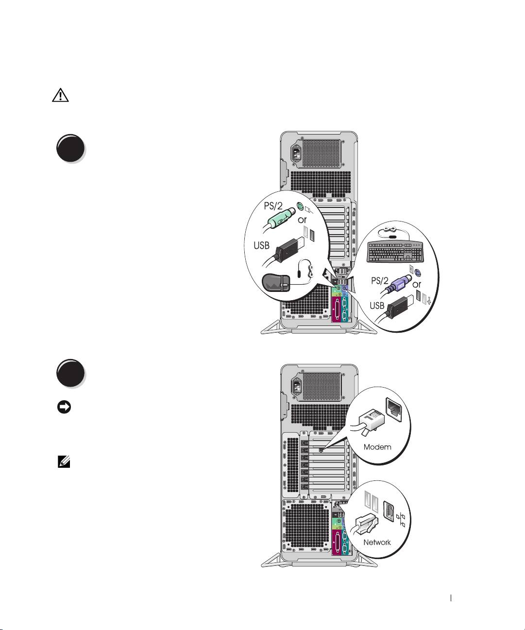
Connect the keyboard and the mouse.
1
Connect the modem or the network cable.
2
NOTICE: Do not connect a modem cable to
the network adapter. Voltage from telephone
communications can damage the network adapter.
NOTE: If your computer has a network card installed,
connect the network cable to the card.
Quick Reference Guide 9
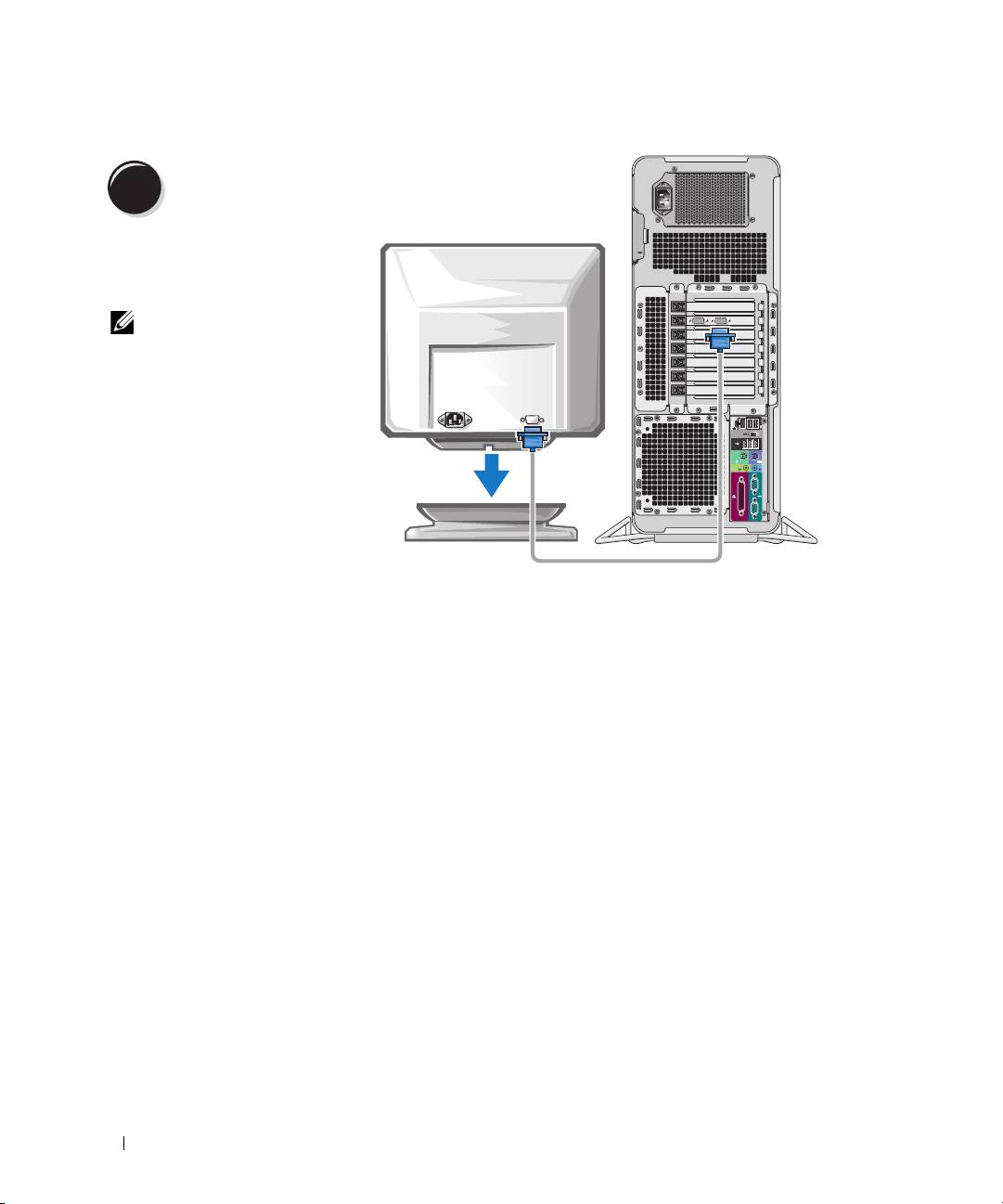
Connect the monitor.
3
Depending on your graphics
card, you can connect your
monitor in various ways.
NOTE: You may need to use
the provided adapter or
cable to connect your
monitor to the computer.
10 Quick Reference Guide
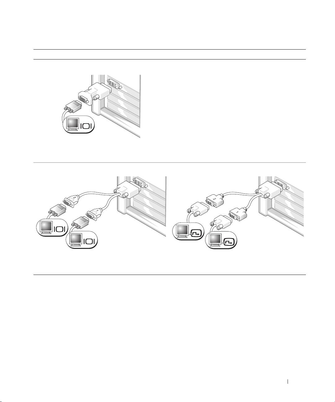
For single- and dual-monitor capable cards with a single connector
One VGA adapter:
VGA
Use the VGA adapter when you have a single-monitor
graphics card and you want to connect your computer
to a VGA monitor.
Dual VGA Y cable adapter:
Dual DVI Y cable adapter:
VGA
DVI
VGA
DVI
Use the appropriate Y cable when your graphics card has a
Use the appropriate Y cable when your graphics card has a
single connector and you want to connect your computer
single connector and you want to connect your computer
to one or two VGA monitors.
to one or two DVI monitors.
The dual-monitor cable is color-coded; the blue connector is for the primary monitor, and the black
connector is for the second monitor. To enable dual-monitor support, both monitors must be attached
to the computer when you start the computer.
Quick Reference Guide 11
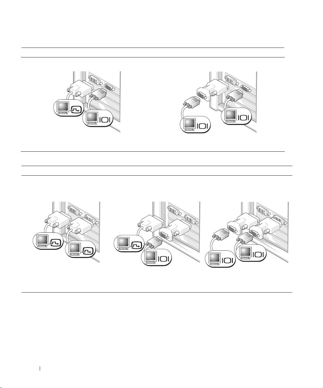
For dual-monitor capable cards with one DVI connector and one VGA connector
One DVI connector and one VGA connector:
Two VGA connectors with one VGA adapter:
DVI
VGA
VGA
VGA
Use the appropriate connector(s) when you want
Use the VGA adapter when you want to connect
to connect your computer to one or two monitors.
your computer to two VGA monitors.
For dual-monitor capable cards with two DVI connectors
Two DVI connectors:
Two DVI connectors with one VGA
Two DVI connectors with two VGA
adapter:
adapters:
DVI
DVI
DVI
VGA
VGA
VGA
Use the DVI connectors to connect
Use the VGA adapter to connect a
Use two VGA adapters to connect
your computer to one or two DVI
VGA monitor to one of the DVI
two VGA monitors to the DVI
monitors.
connectors on your computer
connectors on your computer.
12 Quick Reference Guide
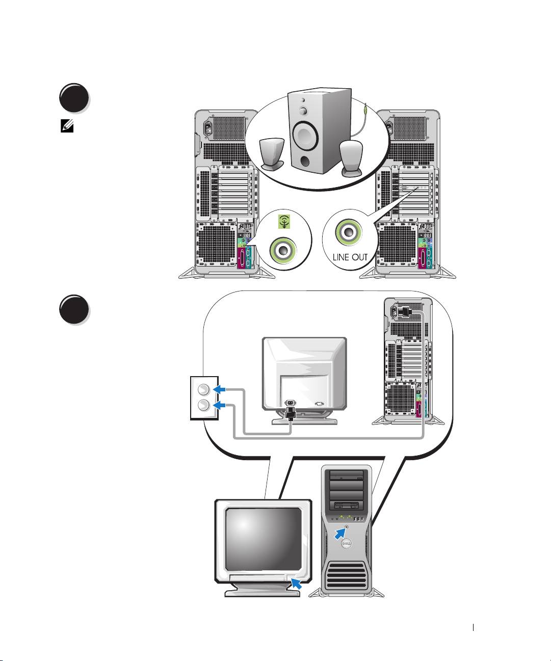
Connect the speakers.
4
NOTE: If your
computer has a sound
card installed, connect
the speakers to the
card.
Connect the power
cables and turn on the
5
computer and monitor.
Quick Reference Guide 13

Install additional software or devices.
6
Before you install any devices or software that did not come with your computer, read the documentation
that came with the software or device or contact the vendor to verify that the software or device is
compatible with your computer and operating system.
You have now completed the setup for your computer.
About Your Computer
CAUTION: Your computer is heavy (it has an approximate minimum weight of 55 lbs) and can be difficult to
maneuver. Seek assistance before attempting to lift, move, or tilt it; this computer requires a two-man lift.
Always lift correctly to avoid injury; avoid bending over while lifting. See your Product Information Guide
for other important safety information.
CAUTION: Before setting your computer upright, install the computer stand. Failure to install the stand before
setting the computer upright could cause the computer to tip over, potentially resulting in bodily injury or damage
to the computer.
14 Quick Reference Guide
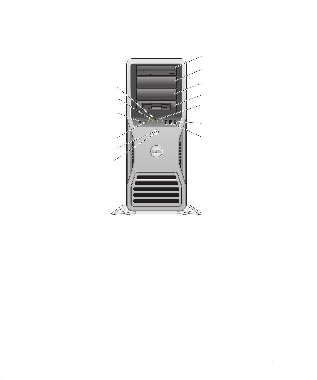
Front View
Quick Reference Guide 15
1
2
3
13
4
12
5
11
6
10
7
9
8

1-3 5.25-inch drive bays Can hold a CD/DVD drive, or a Media Card Reader, floppy drive, or SATA hard
drive in a 5.25-inch drive bay carrier.
NOTE: The drive carriers are only for use in the 5.25-inch drive bays. The
floppy-drive/ Media Card Reader and hard-drive carriers are not interchangeable.
4 5.25-inch drive bay with
Can hold a CD/DVD drive, or a Media Card Reader, floppy drive, or SATA hard
special 3.5-inch drive
drive in a 5.25-inch drive bay carrier. The drive-panel plate shown here is only for
panel plate
use with a floppy drive or Media Card Reader; it can be installed in front of any of
the four 5.25-inch drive bays. For more information, see your User’s Guide.
NOTE: The drive carriers are only for use in the 5.25-inch drive bays. The floppy drive/
Media Card Reader and hard drive carriers are not interchangeable.
5 hard-drive activity light The hard drive light is on when the computer reads data from or writes data to the
hard drive. The light might also be on when a device such as your CD player is
operating.
6 IEEE 1394 connector Use the IEEE 1394 connector for high-speed data devices such as digital video
cameras and external storage devices.
16 Quick Reference Guide

7 USB 2.0 connectors (2) Use the front USB connectors for devices that you connect occasionally, such as
flash memory keys, cameras, or bootable USB devices (see your User’s Guide for
more information).
It is recommended that you use the back USB connectors for devices that typically
remain connected, such as printers and keyboards.
8 power button Press to turn on the computer.
NOTICE: To avoid losing data, do not use the power button to turn off the
computer. Instead, perform an operating system shutdown.
NOTE: The power button can also be used to wake the system or to place it into
a power-saving state. See your User’s Guide for more information.
9 power light The power light illuminates and blinks or remains solid to indicate different states:
• No light — The computer is turned off or in a hibernation mode.
• Steady green — The computer is in a normal operating state.
• Blinking green — The computer is in a power-saving state.
• Blinking or solid amber — See "Power Problems" in your
User’s Guide
.
To exit from a power-saving state, press the power button or use the keyboard or
the mouse if it is configured as a wake device in the Windows Device Manager.
For more information about sleep states and exiting from a power-saving state,
see your User’s Guide.
See "Diagnostic Lights" on page 35 for a description of light codes that can help
you troubleshoot problems with your computer.
10 microphone connector Use the microphone connector to attach a personal computer microphone
for voice or musical input into a sound or telephony program.
11 headphone connector Use the headphone connector to attach headphones.
12 network link light The network link light is on when a good connection exists between a 10-Mbps,
100-Mbps, or 1000-Mbps (or 1-Gbps) network and the computer.
13 diagnostic lights (4) Use these lights to help you troubleshoot a computer problem based on the
diagnostic code. For more information, see "Diagnostic Lights" on page 35.
Quick Reference Guide 17
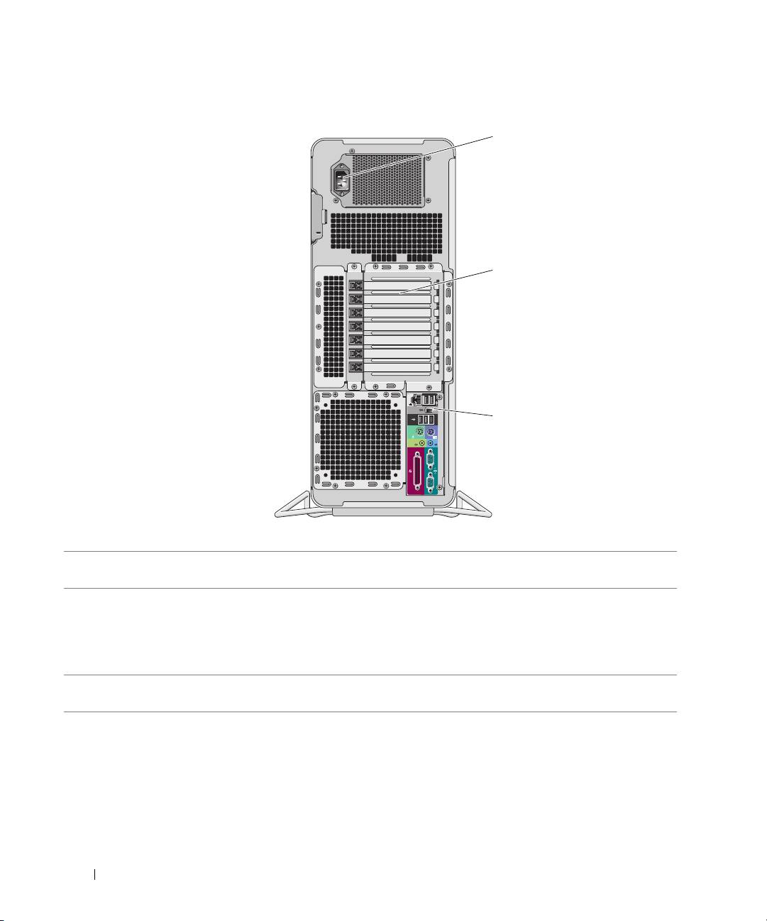
Back View
18 Quick Reference Guide
1
2
3
1 power connector Insert the power cable. The appearance of this connector may differ from what is
pictured here.
2 card slots Access connectors for any installed PCI, PCI-X, or PCI Express cards.
NOTE: The center five connector slots support full-length cards: one PCI, one PCI
express x16, one PCI express x8 (wired as x4), and two PCI-X slots; the connector
slots at the top and at the bottom support half-length cards: two PCI express x8 slots
(wired as x4).
3 back panel connectors Plug serial, USB, and other devices into the
appropriate connector
(see "Back Panel Connectors" on page 19).
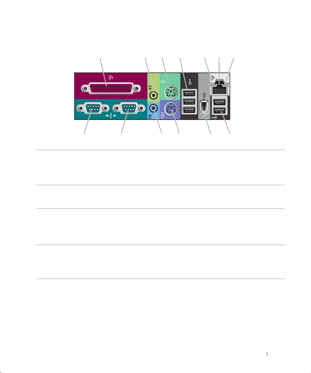
Back Panel Connectors
Quick Reference Guide 19
1 234 6
13 12 11 10 89
57
1 parallel connector Connect a parallel device, such as a printer, to the parallel connector. If you have
a USB printer, plug it into a USB connector.
NOTE: The integrated parallel connector is automatically disabled if the computer
detects an installed card containing a parallel connector configured to the same
address. For more information, see your User’s Guide.
2 line-out/ headphone
Use the green line-out connector to attach headphones and most speakers with
connector
integrated amplifiers.
On computers with a sound card, use the connector on the card.
3 mouse connector Plug a standard mouse into the green mouse connector. Turn off the computer
and any attached devices before you connect a mouse to the computer. If you have
a USB mouse, plug it into a USB connector.
®
®
If your computer is running the Microsoft
Windows
XP operating system,
the necessary mouse drivers have been installed on your hard drive.
4 USB 2.0 connectors (3) It is recommended that you use the front USB connectors for devices that you
connect occasionally, such as flash memory keys, cameras, or bootable USB
devices.
Use the back USB connectors for devices that typically remain connected,
such as printers and keyboards.

5 link integrity light
• Green — A good connection exists between a 10-Mbps network and the
computer.
• Orange — A good connection exists between a 100-Mbps network and the
computer.
• Yellow — A good connection exists between a 1000-Mbps (or 1-Gbps) network
and the computer.
• Off — The computer is not detecting a physical connection to the network.
6 network adapter
To attach your computer to a network or broadband device, connect one end
connector
of a network cable to either a network jack or your network or broadband device.
Connect the other end of the network cable to the network adapter connector
on your computer. A click indicates that the network cable has been securely
attached.
NOTE: Do not plug a telephone cable into the network connector.
On computers with an additional network connector card, use the connectors
on the card and on the back of the computer when setting up multiple network
connections (such as a separate intra- and extranet).
It is recommended that you use Category 5 wiring and connectors for your
network. If you must use Category 3 wiring, force the network speed to 10 Mbps
to ensure reliable operation.
7 network activity light Flashes a yellow light when the computer is transmitting or receiving network
data. A high volume of network traffic may make this light appear to be in a steady
"on" state.
8 USB 2.0 connectors (2) It is recommended that you use the front USB connectors for devices that you
connect occasionally, such as flash memory keys, cameras, or bootable USB
devices.
Use the back USB connectors for devices that typically remain connected,
such as printers and keyboards.
9 IEEE 1394 connector Use the IEEE 1394 connector for high-speed data devices such as digital video
cameras and external storage devices.
10 keyboard connector If you have a standard keyboard, plug it into the purple keyboard connector.
If you have a USB keyboard, plug it into a USB connector.
11 line-in connector Use the blue line-in connector to attach a record/playback device such as a cassette
player, CD player, or VCR.
On computers with a sound card, use the connector on the card.
12 serial connector Connect a serial device, such as a handheld device, to the serial port. If necessary,
the address for this port can be modified through System Setup (see your User’s
Guide for more information).
13 serial connector Connect a serial device, such as a handheld device, to the serial port. If necessary,
the address for this port can be modified through System Setup (see your User’s
Guide for more information).
20 Quick Reference Guide
