Dell POWEREDGE M915: инструкция
Раздел: Профоборудование
Тип: Аппарат
Инструкция к Аппарату Dell POWEREDGE M915
Оглавление
- Примечания, предупреждения и предостережения
- Установка и настройка Распаковка системы Установка направляющих и системы в стойку
- Установка блейд-систем Подключение модулей контроллера шасси и KVM
- Подключение электропитания к системе
- Включение системы Включение блейд-систем
- Завершение установки операционной системы Поддерживаемые операционные системы Операционная система
- Операционная система
- Операционная система
- Операционная система
- Операционная система
- Прочая полезная информация Получение технической поддержки
- Технические характеристики Технические характеристики модуля Процессор Память
- Память (продолжение)
- Память (продолжение)
- Накопители (продолжение) Разъемы
- Разъемы (продолжение) Расширение PCIe Карты Mezzanine
- Карты Mezzanine (продолжение) Встроенные контроллеры Ethernet Видеоконтроллер Физические характеристики
- Физические характеристики (продолжение) Аккумулятор
- Технические характеристики модульного корпуса Физические характеристики Модуль блока питания Дополнительный модуль Avocent iKVM
- Модуль контроллера шасси Панель управления модульного корпуса Условия эксплуатации
- Условия эксплуатации (продолжение) Технические характеристики модуля ввода-вывода

Dell PowerEdge
M1000e, M915, M910, M905,
M805, M710HD, M710, M610x,
M610, M605, and M600
Getting Started
With Your System
Začínáme se systémem
Guide de mise en route
Erste Schritte mit dem System
Τα πρώτα βήµατα µε το σύστηµά σας
Rozpoczęcie pracy z systemem
Начало работы с системой
Procedimientos iniciales con el sistema
Sisteminizi Kullanmaya Başlarken
תכרעמה םע הדובעה תליחת


Dell PowerEdge
M1000e, M915, M910, M905,
M805, M710HD, M710, M610x,
M610, M605, and M600
Getting Started
With Your System
Model BMX01, HHB Series, FHB Series
Notes, Cautions, and Warnings
NOTE: A NOTE indicates important information that helps you make better use of
your computer.
CAUTION: A CAUTION indicates potential damage to hardware or loss of data
if instructions are not followed.
WARNING: A WARNING indicates a potential for property damage,
personal injury, or death.
____________________
Information in this publication is subject to change without notice.
© 2010 Dell Inc. All rights reserved.
Reproduction of these materials in any manner whatsoever without the written permission of Dell Inc.
is strictly forbidden.
Trademarks used in this text: Dell™, the DELL logo, and PowerEdge™ are trademarks of Dell Inc.
®
Citrix™ and XenServer
are either registered trademarks or trademarks of Citrix Systems, Inc. and/
or one or more of its subsidiaries, and may be registered in the United States Patent and Trademark
®
Office and in other countries. Intel
is a registered trademark of Intel Corporation in the U.S. and
®
®
®
other countries. Microsoft
, Windows
, and Windows Server
are either trademarks or registered
®
trademarks of Microsoft Corporation in the United States and/or other countries. Red Hat
and Red
®
Hat Enterprise Linux
are registered trademarks of Red Hat Inc.in the United States and other
®
countries. SUSE
is a registered trademark of Novell, Inc., in the United States and other countries.
®
VMware
is a registered trademark or trademark (the "Marks") of VMware, Inc. in the United States
and/or other jurisdictions. Solaris™ is a trademark of Sun Microsystems, Inc. in the United States and
other countries.
Other trademarks and trade names may be used in this publication to refer to either the entities claiming
the marks and names or their products. Dell Inc. disclaims any proprietary interest in trademarks and
trade names other than its own.
Model BMX01, HHB Series, FHB Series
December 2010 P/N YCFM1 Rev. A00
Installation and Configuration
WARNING: Before performing the following procedure, review the safety
instructions that came with the system.
This section describes the steps required to set up your system for the first time.
Unpack the System
Unpack your system and identify each item.
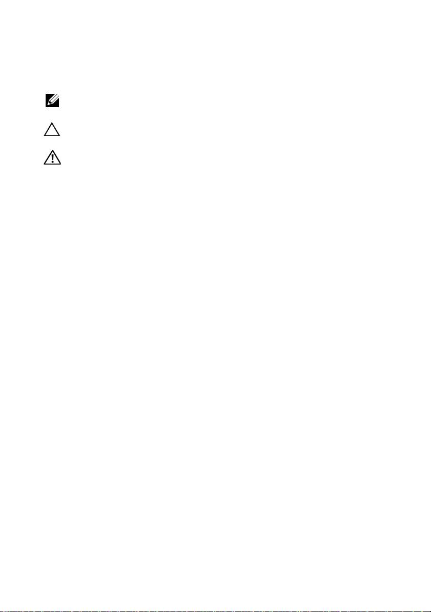
Installing the Rails and System in a Rack
Assemble the rails and install the system in the rack following the
safety instructions and the rack installation instructions provided
with your enclosure.
Getting Started With Your System 3
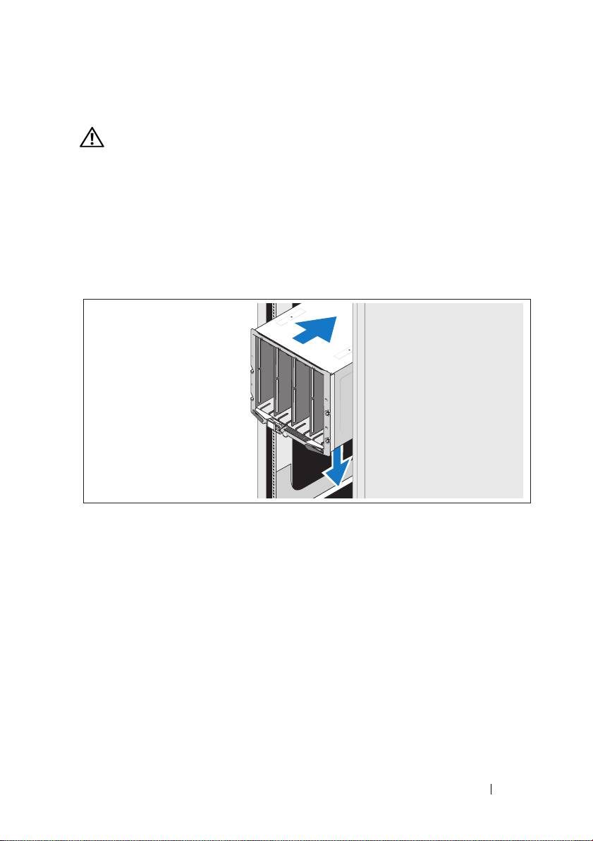
Installing the Blades
Beginning at the top, slide the modules into the enclosure from left to right.
When the blade is securely installed, the handle returns to the closed position.
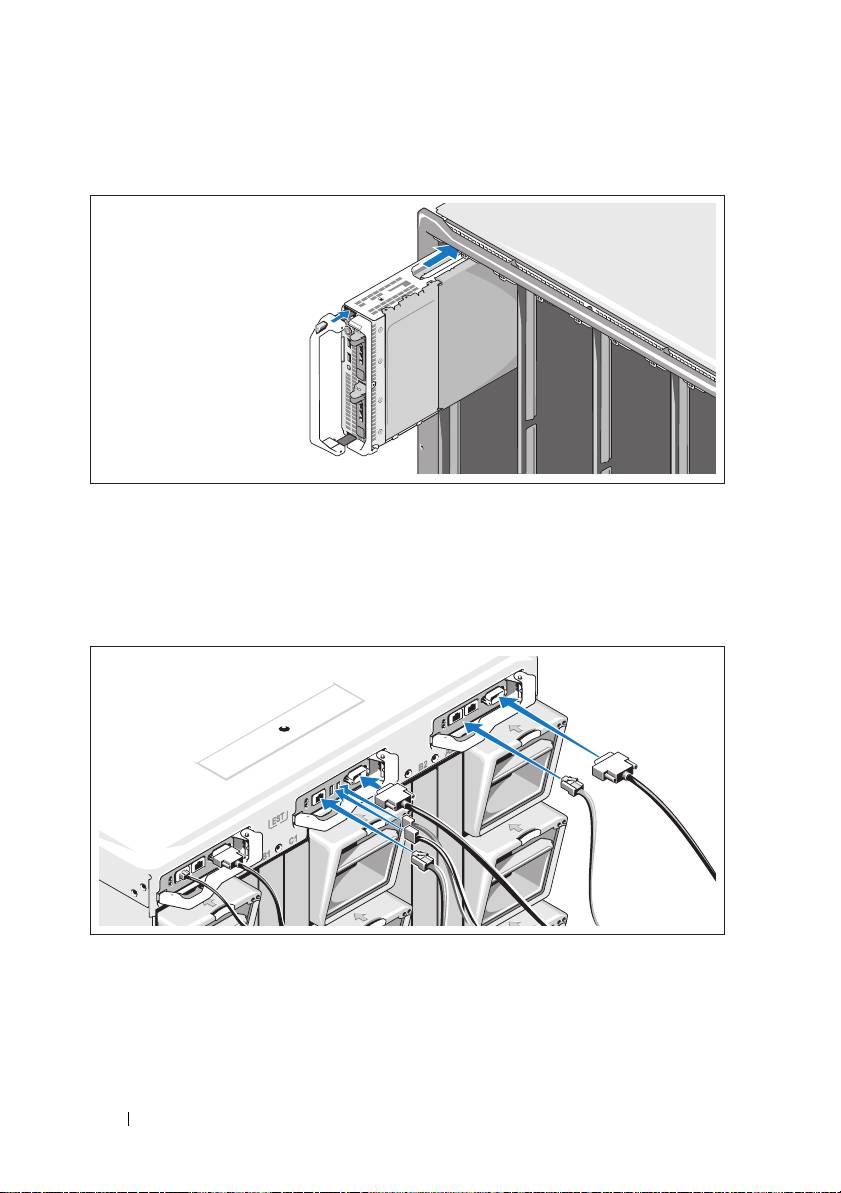
Connecting the CMC and KVM Modules
Connect the serial cable and network cable(s) from the management
system to the CMC module. If a second, optional CMC module is installed,
connect it as well.
Connect the keyboard, mouse, and monitor to the optional iKVM module.
4 Getting Started With Your System
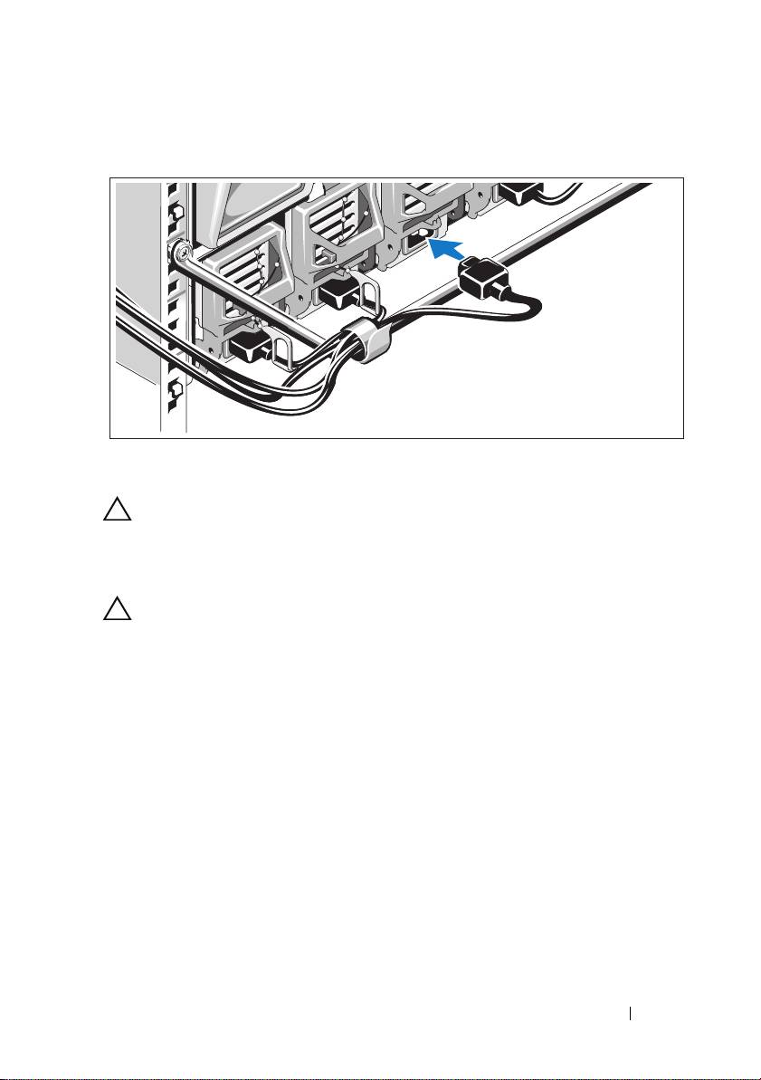
Connecting the System to Power
Connect the system’s power cables to the system power supplies.
CAUTION: To prevent the power cables from being disconnected accidentally,
use the plastic clip on each power supply to secure the power cable to the
power supply, and use the Velcro strap to secure the cable to the strain-relief bar.
Plug the other end of the power cables into a power distribution unit (PDU).
CAUTION: Do not plug the power cables directly into a power outlet; you must
use a PDU. For optimal system functionality, a minimum of three power supplies
are required.
Getting Started With Your System 5
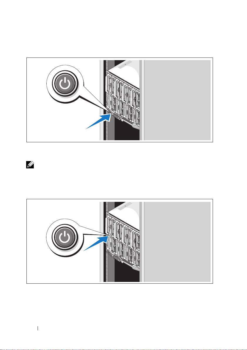
Turning On the System
Press the power button on the enclosure. The power indicator should light.
NOTE: Once you have connected the system to the power supplies, there may
be a minimal delay before you can turn on your system.
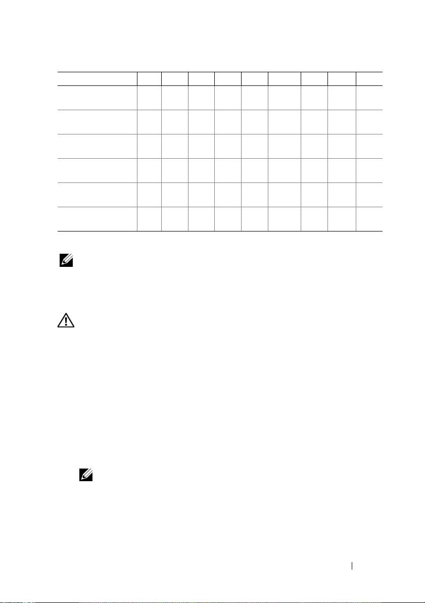
Turning On the Blades
Press the power button on each blade, or power on the blades using the
systems management software.
6 Getting Started With Your System

Complete the Operating System Setup
If you purchased a preinstalled operating system, see the operating system
documentation that ships with your system. To install an operating system
for the first time, see the installation and configuration documentation
for your operating system. Be sure the operating system is installed before
installing hardware or software not purchased with the system.
Supported Operating Systems
Operating System
M915
M910 M905 M805 M710
M710HD
M610 M610x M605
Citrix XenServer 5.5
Citrix XenServer 5.6
Microsoft Windows
Server 2008 Hyper-V
Server
Microsoft Windows
Essential
Business Server 2008
Standard and
Premium Editions
Microsoft Windows
HPC Server 2008
(x64)
Microsoft Windows
Server 2008
Standard and
Enterprise (x86)
Editions
Microsoft Windows
Web Server 2008
(x86) Edition
Microsoft Windows
Web Server 2008
(x86) Edition
with SP2
Getting Started With Your System 7

Operating System
M915
M910 M905 M805 M710
M710HD
M610 M610x M605
Microsoft Windows
Server 2008
Standard and
Enterprise (x86)
Editions with SP2
Microsoft Windows
Server 2008
Standard, Enterprise,
and Datacenter
(x64) Editions
Microsoft Windows
Web Server 2008
(x64) Edition
Microsoft Windows
Web Server 2008
(x64) Edition
with SP2
Microsoft Windows
Server 2008 R2
Standard, Enterprise,
and Datacenter
(x64) Editions
Microsoft Windows
Server 2003 Standard
and Enterprise
Editions
Microsoft Windows
Server 2003
Web Edition
Microsoft Windows
Server 2003
Standard, Enterprise,
and Web Editions
with SP1 and later
Microsoft Windows
Server 2003 R2
Standard and
Enterprise (x86)
Editions
8 Getting Started With Your System

Operating System
M915
M910 M905 M805 M710
M710HD
M610 M610x M605
Microsoft Windows
Server 2003
Standard and
Enterprise (x64)
Editions
Microsoft Windows
Server 2003 R2
Standard and
Enterprise (x64)
Editions
Microsoft Windows
Server 2003 R2
Datacenter (x64)
Edition
Microsoft Windows
Server 2003 R2
Standard, Enterprise,
and Datacenter
(x64) Editions
with SP2
Red Hat Enterprise
Linux AS, ES,
and WS (version 4.0)
Update 5 (x86)
Red Hat Enterprise
Linux AS, ES,
and WS (version 4.0)
Update 5 (x86_64)
Red Hat Enterprise
Linux
AS and
ES (version 4.7)
(x86)
Red Hat Enterprise
Linux
AS and
ES (version 4.7)
(x86_64)
Red Hat Enterprise
Linux
AS and
ES (version 4.8)
(x86)
Getting Started With Your System 9

Operating System
M915
M910 M905 M805 M710
M710HD
M610 M610x M605
Red Hat Enterprise
Linux
AS and
ES (version 4.8)
(x86_64)
Red Hat Enterprise
Linux
(version 5.0) (x86)
Red Hat Enterprise
Linux (version 5.0)
(x86_64)
Red Hat Enterprise
Linux (version 5.2)
(x86)
Red Hat Enterprise
Linux
(version 5.5)
(x86)
Red Hat Enterprise
Linux
(version 5.5)
(x86_64)
Red Hat Enterprise
Linux
(version 6.0)
(x86_64)
SUSE Linux
Enterprise Server 10
(x86_64)
SUSE Linux
Enterprise Server 10
(x86_64) SP3
SUSE Linux
Enterprise Server 11
(x86_64)
Solaris 10 (x86_64)
VMware ESX
version 3.0
VMware ESX version
3.0.2 Update 1
VMware ESX
version 3.5
10 Getting Started With Your System
Operating System
M915
M910 M905 M805 M710
M710HD
M610 M610x M605
VMware ESX
version 4.0 Update 1
VMware ESXi
version 4.0 Update 1
VMware ESX
version 4.0 Update 2
VMware ESXi
version 4.0 Update 2
VMware ESX
version 4.1 Update 1
VMware ESXi
version 4.1 Update 1
—Supported
NOTE: For the latest information on supported operating systems for all
PowerEdge systems, see dell.com/ossupport.
Other Information You May Need
WARNING: Before performing the following procedure, review the safety
instructions that came with the system.
• The
Configuration Guide
provides information on configuring the system
enclosure and the blades.
•
Rack Installation Instructions
included with your rack solution describes
how to install your system into a rack.
• The
Hardware Owner’s Manual
provides information about system
features and describes how to troubleshoot the system and install or
replace system components.
• Dell systems management application documentation provides
information about installing and using the systems management software.
NOTE: Always check for updates on support.dell.com/manuals and read the
updates first because they often supersede information in other documents.
Getting Started With Your System 11

Obtaining Technical Assistance
If you do not understand a procedure in this guide or if the system does not
perform as expected, see your Hardware Owner’s Manual. Dell offers
comprehensive hardware training and certification. See dell.com/training for
more information. This service may not be offered in all locations.
Technical Specifications
Blade Specifications
Processor
Processor type
PowerEdge M915
Two or four AMD Opteron 6000 series processors
(eight- or twelve-core processors)
PowerEdge M910
Two or four Intel Xeon
7000 series processors
(up to eight-core processors)
PowerEdge M905
Four dual- or quad-core AMD Opteron 8000 series
processors
PowerEdge M805
Two dual- or quad-core AMD Opteron 2000 series
processors
PowerEdge M710HD,
One or two dual-, quad-, or six-core Intel Xeon 5000
M710, M610x, M610
series processors
PowerEdge M605
One or two dual- or quad-core AMD Opteron 2000
series processors
PowerEdge M600
One or two dual- or quad-core Intel Xeon processors
Memory
Architecture
PowerEdge M915
1333 MHz DDR3 single-, dual-, or quad-ranked
registered LV DIMMs (RDIMMs)
PowerEdge M910
DDR3 memory modules, rated for 1066 MHz
operation
PowerEdge M905,
DDR2 memory modules, rated for 677 MHz
M805, M605
operation
12 Getting Started With Your System

Memory (continued)
PowerEdge M710HD
DDR3 and DDR3L single-, dual-, and quad-rank
memory modules, rated for1066 and 1333 MHz
PowerEdge M710,
800, 1066, or 1333 MHz DDR3 single- or dual-ranked
M610x, M610,
registered DIMMs (RDIMMs) or unbuffered DIMMs
(UDIMMs)
or
800 or 1066 MHz DDR3 quad-ranked registered
DIMMs (RDIMMs) or unbuffered DIMMs
(UDIMMs)
PowerEdge M600
FBD memory modules, rated for 677 MHz operation
Memory module sockets
PowerEdge M915, M910
32 240-pin sockets
PowerEdge M905
24 240-pin sockets
PowerEdge M805
16 240-pin sockets
PowerEdge M710HD,
18 240-pin sockets
M710
PowerEdge M610x, M610
12 240-pin sockets
PowerEdge M605, M600
Eight 240-pin sockets
Memory module capacities
PowerEdge M915
1 GB, 2 GB, 4 GB, 8 GB, and 16 GB LV DIMMs
PowerEdge M910
1 GB, 2 GB, 4 GB, 8 GB, and 16 GB RDIMMs
PowerEdge M905, M805
1 GB, 2 GB, 4 GB, and 8 GB
PowerEdge M710HD
1 GB, 2 GB, 4 GB, 8 GB, and 16 GB
RDIMMs and LV DIMMs
PowerEdge M710,
2 GB, 4 GB, 8 GB, and 16 GB RDIMMs and LV DIMMs;
M610x, M610
1 GB and 2 GB UDIMMs
PowerEdge M605, M600
512 MB, 1 GB, 2 GB, 4 GB, and 8 GB
Minimum RAM
PowerEdge M915
8 GB
PowerEdge M910
4 GB
PowerEdge M905
8 GB (Eight 1 GB memory modules)
Getting Started With Your System 13

Memory (continued)
PowerEdge M805
4 GB (Four 1 GB memory modules)
PowerEdge M710D
4 GB
PowerEdge M710,
One 1 GB memory module (one-processor system) or
M610x, M610
two 1 GB memory modules (two-processor systems)
PowerEdge M605, M600
1 GB (two 512 MB memory modules)
Maximum RAM
PowerEdge M915
512 GB
PowerEdge M910
512 GB
PowerEdge M905
192 GB
PowerEdge M805
128 GB
PowerEdge M710HD
288 GB
PowerEdge M710
288 GB (Eighteen 16 GB RDIMMs);
36 GB (Eighteen 2 GB UDIMMs)
PowerEdge M610x,
192 GB (Twelve 16 GB RDIMMs);
M610
24 GB (Twelve 2 GB UDIMMs)
PowerEdge M605, M600
64 GB
Drives
Hard Drives
PowerEdge M915, M910
Up to two 2.5-inch SAS hard drives support through
value RAID or performance RAID storage card.
or
Up to two 2.5-inch SSD hard drives support through
value RAID or performance RAID storage card.
PowerEdge M905, M805
Up to two 2.5-inch SAS hard drives support through
value RAID or performance RAID storage card.
PowerEdge M710HD
Up to two 2.5-inch SAS hard drives support through
PERC H200 embedded storage controller.
or
Up to two 2.5-inch SSD hard drives support through
PERC H200 embedded storage controller.
14 Getting Started With Your System

Drives (continued)
PowerEdge M710
Up to four 2.5-inch SAS hard drives support through
value RAID or performance RAID storage card.
PowerEdge M600,
One 2.5-inch SATA hard drive support through non-
M610x, M610
RAID, value RAID, or performance RAID
storage card.
or
Two 2.5-inch SATA hard drives support through value
RAID or performance RAID storage card.
or
One solid-state disk (SSD) hard drive support
through non-RAID storage card.
or
Up to two SAS hard drives support through value
RAID or performance RAID storage card.
PowerEdge M605
Up to two SATA hard drives support through value
RAID or performance RAID storage card.
or
Up to two solid-state disk (SSD) hard drives support
through non-RAID storage card.
or
Up to two SAS hard drives support through value
RAID or performance RAID storage card.
NOTE: For all modular systems, SAS and SATA hard
drives cannot be mixed within a blade.
NOTE: Hot-plug operation is supported if an optional
RAID controller card is installed.
Connectors
External
USB
PowerEdge M915, M910,
Three 4-pin, USB 2.0 compliant
M905, M805, M710
PowerEdge M710HD,
Two 4-pin, USB 2.0 compliant
M610x, M610, M605,
M600
Getting Started With Your System 15

Connectors (continued)
Internal
Internal Secure Digital
One optional flash memory card slot
(SD) module (PowerEdge
with the internal SD module.
M915, M910, M905, M805,
M710HD, M710,
M610x, M610)
Internal Secure Digital
One optional vFlash memory card slot for
(SD) vFlash module
use with the iDRAC Enterprise support.
(PowerEdge M915, M910,
M710HD, M710,
M610x, M610)
USB key (PowerEdge M915,
One internal USB key connector.
M910, M710HD,
M710, M610x, M610)
PCIe Expansion Solution
PowerEdge M610x Supports two single-wide or one double-wide
full length standard PCIe card.
Mezzanine Cards
PowerEdge M915, M910 Up to four PCIe Gen 2 x8 mezzanine card slots,
supporting dual-port Gb Ethernet, 10 Gb Ethernet,
FC8 Fibre Channel, or Infiniband mezzanine cards.
PowerEdge M905, M805 Up to four PCIe Gen 1 x8 mezzanine card slots,
supporting dual-port Gb Ethernet, 10 Gb Ethernet,
FC8 or FC4 Fibre Channel, or 4x DDR Infiniband
mezzanine cards.
PowerEdge M710HD Up to two PCIe Gen 2 x8 mezzanine card slots,
supporting dual-port and quad-port Gb Ethernet,
10 Gb Ethernet, FC8 or FC4 Fibre Channel,
or 4x DDR Infiniband mezzanine cards.
PowerEdge M710 Up to four PCIe Gen 2 mezzanine card slots (three x8
and one x4 lane width), supporting dual-port Gb
Ethernet, 10 Gb Ethernet, FC8 or FC4 Fibre
Channel, or 4x DDR Infiniband mezzanine cards.
16 Getting Started With Your System

Mezzanine Cards (continued)
PowerEdge M610x, M610 Up to two PCIe Gen 2 x8 mezzanine card slots,
supporting dual-port Gb Ethernet, 10 Gb Ethernet,
FC8 or FC4 (M610 only) Fibre Channel, or 4x DDR
Infiniband mezzanine cards.
PowerEdge M605, M600 Up to two PCIe x8 mezzanine card slots, supporting
dual-port Gb Ethernet, 10 Gb Ethernet, FC8 or
FC4 Fibre Channel, or 4x DDR Infiniband
mezzanine cards.
Embedded Ethernet Controllers
PowerEdge M915, M910,
Four Ethernet ports with TOE and iSCSI boot
M905, M805, M710HD,
support, provided by two integrated dual-port
M710
Broadcom 5709S Ethernet controllers.
PowerEdge M610x, M610 Two Ethernet ports with TOE and iSCSI boot
support, provided by one integrated dual-port
Broadcom 5709S Ethernet controller.
PowerEdge M605, M600 Two Ethernet ports with TOE and iSCSI boot
support, provided by two integrated Broadcom 5708S
controllers.
Video Controller
PowerEdge M905, M805,
ATI RN50 video controller. 32 MB video memory
M605, M600
PowerEdge M915, M910,
Matrox G200 video controller. 8 MB video memory
M710HD, M710, M610x,
M610
Physical
PowerEdge M915
Height
38.5 cm (15.2 in)
Width
5 cm (2 in)
Depth
48.6 cm (19.2 in)
Weight (maximum
12.7 kg (28 lb)
configuration)
Getting Started With Your System 17

Physical (continued)
PowerEdge M910
Height
38.5 cm (15.2 in)
Width
5 cm (2 in)
Depth
48.6 cm (19.2 in)
Weight (maximum
13.1 kg (29 lb)
configuration)
PowerEdge M905, M805,
M710, M610x
Height
38.5 cm (15.2 in)
Width
5 cm (2 in)
Depth
48.6 cm (19.2 in)
Weight (maximum
11.1 kg (24.5 lb)
configuration)
PowerEdge M710HD
Height
18.9 cm (7.4 in)
Width
5 cm (2 in)
Depth
48.6 cm (19.2 in)
Weight (maximum
7.4 kg (16.3 lb)
configuration)
PowerEdge M605, M600
Height
18.9 cm (7.4 in)
Width
5 cm (2 in)
Depth
48.6 cm (19.2 in)
Weight (maximum
5.2–6.4 kg (11.5–14.0 lb)
configuration)
Battery
NVRAM backup battery CR 2032 3.0-V lithium coin cell
18 Getting Started With Your System
