Dell PowerEdge VRTX – страница 3
Инструкция к Компьютеру Dell PowerEdge VRTX
Оглавление
8. Close the server module.
9. Install the server module in the enclosure.
Management Riser Card
The management riser card provides two SD card slots and a USB interface dedicated for the embedded hypervisor.
This card offers the following features:
• Internal Dual SD interface — maintains a mirrored configuration using SD cards in both slots and provides
redundancy.
• Single card operation — single card operation is supported, but without redundancy.
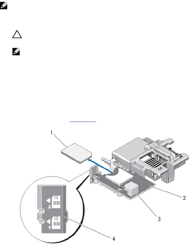
Replacing The SD Card
NOTE: The SD card in the lower card slot is the primary card (SD1) and the SD card in the upper card slot is the
secondary card (SD2).
1. Enter the System Setup and ensure that the Internal SD Card Port is enabled.
CAUTION: If the Internal SD Card Redundancy option is set to Mirror Mode in the Integrated Devices screen
of the system setup, you must follow the instructions in step 4 through step 6 to avoid loss of data.
NOTE: When an SD card failure occurs, the Internal SD Card Redundancy option in the System Setup is set to
disabled and the internal dual SD module controller notifies the system. On the next reboot, the system
displays a message indicating the failure.
2. Remove the server module from the enclosure.
3. If the Internal SD Card Redundancy option is set to Disabled, replace the failed SD card with a new SD card.
4. Install the server module in the enclosure.
5. Enter the System Setup and ensure that the Internal SD Card Port and Internal SD Card Redundancy mode is
enabled.
6. Check if the new SD card is functioning properly.
If the problem persists, see Getting Help.
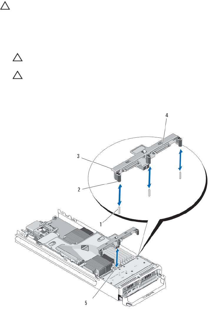
Figure 12. Replacing the SD Card
41
1. SD card
2. management riser card
3. USB connector
4. SD card slots
Internal USB Key
The server module provides an internal USB connector for a USB flash memory key. The USB memory key can be used
as a boot device, security key, or mass storage device. To use the internal USB connector, the Internal USB Port option
must be enabled in the Integrated Devices screen of the System Setup.
To boot from the USB memory key, you must configure the USB memory key with a boot image, and then specify the
USB memory key in the boot sequence in the System Setup. For information on creating a bootable file on the USB
memory key, see the user documentation that accompanied the USB memory key.
Replacing The Internal USB Key
CAUTION: Many repairs may only be done by a certified service technician. You should only perform
troubleshooting and simple repairs as authorized in your product documentation, or as directed by the online or
telephone service and support team. Damage due to servicing that is not authorized by Dell is not covered by your
warranty. Read and follow the safety instructions that came with the product.
CAUTION: To avoid interference with other components in the server module, the maximum allowable dimensions
of the USB key are 15.9 mm wide x 57.15 mm long x 7.9 mm high.
1. Remove the server module from the enclosure.
2. Open the server module.
3. Locate the USB connector / USB key.
4. If installed, remove the USB key.
5. Insert the new USB memory key into the USB connector.
6. Close the server module.
7. Install the server module in the enclosure.
8. Enter the System Setup and verify that the USB key is detected by the system.
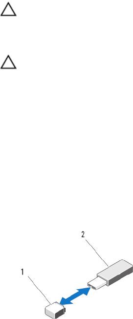
Figure 13. Replacing the USB Memory Key
1. USB memory key connector
2. USB memory key
42
SD vFlash Card
Replacing The SD vFlash Card
1. Remove the server module from the enclosure.
2. If installed, remove the SD vFlash card from the card slot.
NOTE: The SD vFlash card slot is near the Fabric B PCIe mezzanine card slot at the back corner of the server
module.
3. To install the SD vFlash card, insert the contact-pin end of the SD card into the card slot on the VFlash media unit
with the card label side facing up.
NOTE: The slot is keyed to ensure correct insertion of the card.
4. Press inward on the card to lock it into the slot.
5. Install the server module in the enclosure.
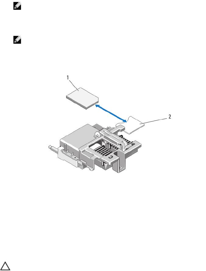
Figure 14. Replacing the SD vFlash Card
1. SD vFlash card
2. SD vFlash card slot
Network Daughter Card/LOM Riser Card
Removing The Network Daughter Card/LOM Riser Card
CAUTION: Many repairs may only be done by a certified service technician. You should only perform
troubleshooting and simple repairs as authorized in your product documentation, or as directed by the online or
telephone service and support team. Damage due to servicing that is not authorized by Dell is not covered by your
warranty. Read and follow the safety instructions that came with the product.
1. Remove the server module from the enclosure.
2. Open the server module.
43
3. Remove the two screws that secure the Network Daughter Card/LOM riser card to the system board.
4. Lift the card from the system board.
5. Close the server module.
6. Install the server module in the enclosure.
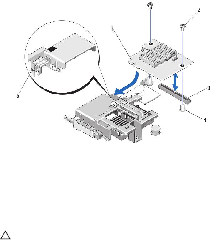
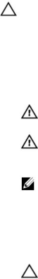
Figure 15. Removing and Installing the Network Daughter Card/LOM Riser Card
1. LOM riser card
5. tab projections (on the plastic bracket
covering the PCIe mezzanine card
2. screws (2)
connectors)
3. LOM riser card connector
4. standoffs (2)
Installing The Network Daughter Card/LOM Riser Card
CAUTION: Many repairs may only be done by a certified service technician. You should only perform
troubleshooting and simple repairs as authorized in your product documentation, or as directed by the online or
telephone service and support team. Damage due to servicing that is not authorized by Dell is not covered by your
warranty. Read and follow the safety instructions that came with the product.
1. Remove the server module from the enclosure.
2. Open the server module.
3. Install the Network Daughter Card/LOM riser card:
a) Align the slots on the card edge with the projection tabs on the plastic bracket covering the PCIe mezzanine
card slots.
b) Lower the card into place until the card connector fits into the corresponding connector on the system board.
c) Secure the card with the two screws.
4. Close the server module.
5. Install the server module in the enclosure.
44
Processors
• Your system supports up to two Intel Xeon processor E5-2600 product family.
• Single-processor configuration is supported.
• Use 57 mm heat sinks for processors up to 95 W and 77 mm heat sinks with 115 W/130 W processors.
• Do not mix processors of different Wattages.
Use the following procedure when:
• Installing an additional processor
• Replacing a processor
Removing A Processor
CAUTION: Many repairs may only be done by a certified service technician. You should only perform
troubleshooting and simple repairs as authorized in your product documentation, or as directed by the online or
telephone service and support team. Damage due to servicing that is not authorized by Dell is not covered by your
warranty. Read and follow the safety instructions that came with the product.
1. Remove the server module from the enclosure.
2. Open the server module.
WARNING: The processor and heat sink can become extremely hot. Be sure the processor has had sufficient
time to cool before handling.
3. Remove the cooling shroud.
CAUTION: Never remove the heat sink from a processor unless you intend to remove the processor. The heat
sink is necessary to maintain proper thermal conditions.
4. Loosen the screws that secure the heat sink to the server module system board.
5. Remove the heat sink.
Set the heat sink upside down on the work surface to avoid contaminating the thermal grease.
45
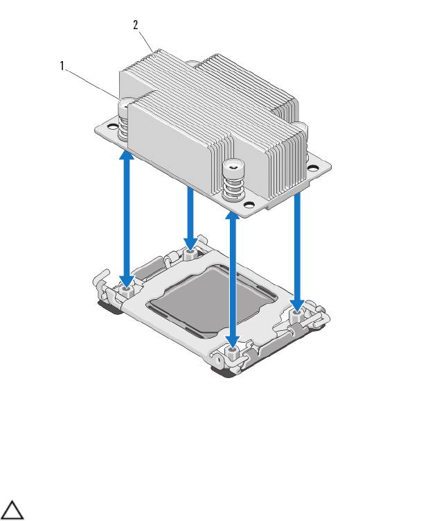
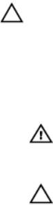
Figure 16. Installing and Removing a Heat Sink
1. screws (4)
2. heat sink
6. Use a clean, lint-free cloth to remove any thermal grease from the surface of the processor shield.
CAUTION: The processor is held in its socket under strong pressure. Be aware that the release lever can
spring up suddenly if not firmly grasped.
7. Position your thumb firmly over the socket-release lever near the label marked OPEN 1st and release the lever from
the locked position by pushing down and out from under the tab.
8. Similarly, release the socket-release lever near the label marked CLOSE 1st from the locked position. Rotate the
lever 90 degrees upward.
46
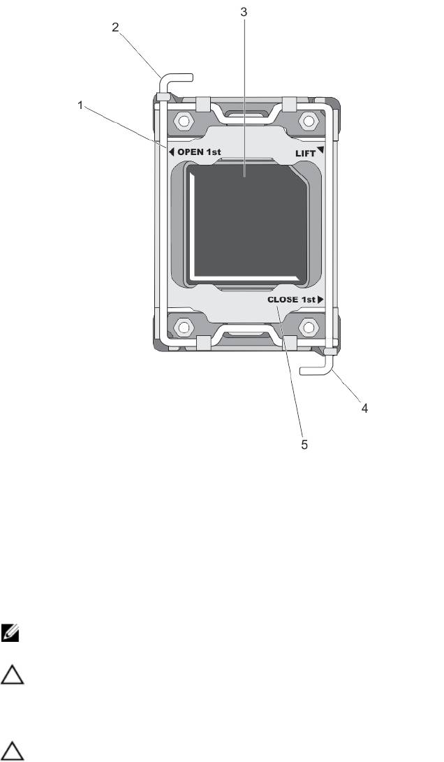
Figure 17. Processor Shield Opening and Closing Lever Sequence
1. OPEN 1st label
4. close first lever
2. open first lever
5. CLOSE 1st label
3. processor
9. Hold the tab on the processor shield and rotate it upward and out of the way.
10. If applicable, remove the socket protective cap from the processor shield. To remove the socket protective cap,
push the cap from the inside of the processor shield and move it away from the socket pins.
NOTE: It is recommended that you install/remove the socket protective cap from the processor shield with the
processor shield in the open position.
CAUTION: The socket pins are fragile and can be permanently damaged. Be careful not to bend the pins in the
socket when removing the processor out of the socket.
11. Lift the processor out of the socket and leave the release lever up so that the socket is ready for the new
processor.
CAUTION: If you are permanently removing a processor, you must install a socket protective cap and a
processor/DIMM blank in the vacant socket to ensure proper system cooling. The processor/DIMM blank
covers the vacant sockets for the DIMMs and the processor.
47
Figure 18. Installing and Removing a Processor
1. socket-release lever 2
6. socket-release lever 1
2. pin-1 corner of processor
7. pin-1 corner on system board
3. tabs (2)
8. processor
4. processor shield
5. socket protective cap
48
Installing A Processor
CAUTION: Many repairs may only be done by a certified service technician. You should only perform
troubleshooting and simple repairs as authorized in your product documentation, or as directed by the online or
telephone service and support team. Damage due to servicing that is not authorized by Dell is not covered by your
warranty. Read and follow the safety instructions that came with the product.
NOTE: If you are installing just one processor, it must be installed in socket CPU1.
1. If applicable, remove the heat-sink blank.
2. Unlatch and rotate the socket-release levers 90 degrees upward and ensure that the socket-release lever is fully
open.
3. Hold the tab near the label marked LIFT on the processor shield and rotate it upward and out of the way.
4. If applicable, remove the socket protective cap from the processor shield. To remove the socket protective cap,
push the cap from the inside of the processor shield and move it away from the socket pins.
NOTE: It is recommended that you install/remove the socket protective cap from the processor shield with the
processor shield in the open position.
CAUTION: Positioning the processor incorrectly can permanently damage the system board or the processor.
Be careful not to bend the pins in the socket.
CAUTION: Do not use force to seat the processor. When the processor is positioned correctly, it engages
easily into the socket.
5. Install the processor in the socket:
a) Identify the pin-1 corner of the processor by locating the tiny gold triangle on one corner of the processor.
Place this corner in the same corner of the ZIF socket identified by a corresponding triangle on the system
board.
b) Align the pin-1 corner of the processor with the pin-1 corner of the system board.
c) Set the processor lightly in the socket.
Because the system uses a ZIF processor socket, do not use force. When the processor is positioned correctly,
it drops down into the socket with minimal pressure.
d) Close the processor shield.
e) Rotate the socket-release lever near the label marked CLOSE 1st until it is locked in position.
f) Similarly, rotate the socket-release lever near the label marked OPEN 1st to the locked position.
CAUTION: Applying too much thermal grease can result in excess grease coming in contact with and
contaminating the processor socket.
6. Install the heat sink:
If you are:
Reinstalling a
Use a clean, lint-free cloth to remove the existing thermal grease from the heat sink.
heat sink
Upgrading a
If a new heat sink was supplied with the processor, install it.
processor
Reinstalling a
Clean any remnants of thermal grease from the processor.
processor
a) Open the grease applicator included with your processor kit and apply all of the thermal grease in the
applicator to the center of the topside of the new processor.
49
b) Place the heat sink onto the processor.
c) Tighten the four screws to secure the heat sink to the server module board.
NOTE: Do not over-tighten the heat sink retention screws when installing the heat sink. To prevent over-
tightening, tighten the retention screw until resistance is felt, and stop once the screw is seated. The
screw tension should be no more than 6 in-lb (6.9 kg-cm).
7. Install the cooling shroud.
8. Close the server module.
9. Install the server module in the enclosure.
As the system boots, it detects the presence of the new processor and automatically changes the system
configuration information in the System Setup.
10. Press <F2> to enter the System Setup and check that the processor information matches the new system
configuration.
11. Run the system diagnostics to verify that the new processor operates correctly.
12. Update the system BIOS.
Hard Drives
• The system supports up to two 2.5 inch SAS/SATA/PCIe SSDs or SAS/SATA hard drives.
• All drives connect to the server module system board through the hard-drive/SSD backplane board.
• Hard drives/SSDs are supplied in special hot-swappable drive carriers that fit in the drive bays.
• SAS/SATA/PCIe SSDs or SAS/SATA hard drives cannot be mixed within a server module.
Hard Drive/SSD Installation Guidelines
For a single-drive configuration, a hard-drive blank must be installed in the other drive bay to maintain proper cooling
airflow.
Removing A Hard Drive/SSD
NOTE: Not all operating systems support hot-swappable drive installation. See the documentation supplied with
your operating system.
1. Take the hard drive/SSD offline and wait until the hard-drive/SSD indicator codes on the drive carrier signal that
the drive may be removed safely.
When all indicators are off, the drive is ready for removal.
See your operating system documentation for more information on taking the drive offline.
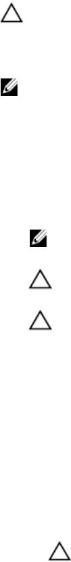
2. Open the hard-drive/SSD carrier handle to release the drive.
3. Slide the hard drive/SSD out until it is free of the drive bay.
If you are permanently removing the hard drive/SSD, install a blank insert.
50
Figure 19. Removing and Installing a Hard Drive/SSD
1. release button
2. hard drive/SSD
3. hard-drive/SSD connector (on backplane)
4. hard-drive/SSD carrier handle
Installing A Hard Drive/SSD
CAUTION: When a replacement hot-swappable hard drive/SSD is installed and the server module is powered on,
the drive automatically begins to rebuild. Make absolutely sure that the replacement hard drive/SSD is blank or
contains data that you wish to have over-written. Any data on the replacement hard drive/SSD is immediately lost
after the drive is installed.
NOTE: Not all operating systems support hot-swappable drive installation. See the documentation supplied with
your operating system.
1. Open the hard-drive/SSD carrier handle.
2. Insert the hard-drive/SSD carrier into the drive bay. Carefully align the channel on the hard-drive/SSD carrier with
the appropriate drive slot on the server module.
3. Push the drive carrier into the slot until the handle makes contact with the server module.
4. Rotate the carrier handle to the closed position while pushing the carrier into the slot until it locks into place.
The status LED indicator displays a steady green light if the drive is installed correctly. The drive carrier LED green
indicator flashes as the drive rebuilds.
Shutdown Procedure For Servicing a Hard Drive
NOTE: This section applies only to situations where the server module must be powered down to service a hard
drive. In many situations, the hard drive can be serviced while the server module is powered on.
51
If you need to power off the server module to service a hard drive, wait 30 seconds after the server module’s power
indicator turns off before removing the hard drive. Otherwise, the hard drive may not be recognized after it is reinstalled
and the server module is powered on again.
Configuring The Boot Drive
The drive or device from which the system boots is determined by the boot order specified in the System Setup.
Removing A Hard Drive/SSD From A Hard-Drive/SSD Carrier
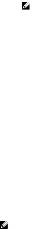
1. Remove the four screws from the slide rails on the hard-drive/SSD carrier.
2. Lift the hard drive/SSD out of the hard-drive/SSD carrier.
Figure 20. Removing and Installing a Hard Drive/SSD in a Hard-Drive/SSD Carrier
1. hard drive/SSD
2. screw holes (4)
3. hard-drive/SSD carrier
4. screws (4)
Installing A Hard Drive/SSD In A Hard-Drive/SSD Carrier
1. Insert the hard drive/SSD into the hard-drive/SSD carrier with the drive’s controller board’s connector end of the
drive at the back of the carrier.
2. From the back of the carrier, slide the drive into the carrier.
3. Align the screw holes on the hard drive/SSD with the holes on the hard-drive/SSD carrier.
CAUTION: To avoid damaging the drive or the carrier, do not overtighten the screws.
4. Attach the four screws to secure the hard drive/SSD to the hard-drive/SSD carrier.
52
Hard-Drive/SSD Backplane
Removing The Hard-Drive/SSD Backplane
CAUTION: Many repairs may only be done by a certified service technician. You should only perform
troubleshooting and simple repairs as authorized in your product documentation, or as directed by the online or
telephone service and support team. Damage due to servicing that is not authorized by Dell is not covered by your
warranty. Read and follow the safety instructions that came with the product.
1. Remove the server module from the enclosure.
2. Open the server module.
CAUTION: You must note the number of each hard drive/SSD and temporarily label them before removal so
that you can replace them in the same locations.
CAUTION: To prevent damage to the hard drives/SSDs and the hard-drive/SSD backplane, you must remove
the hard drives/SSDs from the server module before removing the hard-drive/SSD backplane.
3. Remove the hard drive(s)/SSD(s).
4. Hold both edges of the hard-drive/SSD backplane near the server module chassis and lift the backplane away from
the server module.
Figure 21. Removing and Installing the Hard-Drive/SSD Backplane
53
1. guide pins (3)
4. hard-drive/SSD connectors (2)
2. guides (3)
5. hard-drive backplane/SSD connector
3. hard-drive/SSD backplane
Installing The Hard-Drive/SSD Backplane
1. Open the server module.
2. Align the guides on the hard-drive/SSD backplane with the guide pins on the system board.
3. Press down the backplane until the connectors on the backplane and the system board are fully engaged.
4. Install the hard drives/SSDs in their original locations.
5. Close the server module.
6. Install the server module in the enclosure.
System Board
Removing The System Board
CAUTION: Many repairs may only be done by a certified service technician. You should only perform
troubleshooting and simple repairs as authorized in your product documentation, or as directed by the online or
telephone service and support team. Damage due to servicing that is not authorized by Dell is not covered by your
warranty. Read and follow the safety instructions that came with the product.
1. Remove the server module from the enclosure.
2. Open the server module.
3. Install an I/O connector cover on the I/O connector(s) at the back of the board.
WARNING: The processor and heat sink can become extremely hot. Be sure the processor has had sufficient
time to cool before handling.
WARNING: The memory modules are hot to the touch for some time after the system has been powered
down. Allow time for the memory modules to cool before handling them. Handle the memory modules by the
card edges and avoid touching the components.
NOTE: If you are removing more than one hard drive/SSD, label them so you can replace them in their original
locations.
4. Remove the hard drives/SSDs.
5. Remove the hard-drive/SSD backplane.
6. Remove the cooling shroud.
7. Remove both PCIe mezzanine cards, if present.
CAUTION: Do not lift the system board assembly by grasping a memory module, processor, or other
components.
8. Hold the server module chassis with one hand, lift and pull the system board retention latch with the other hand,
and then slide the system board out of the open end of the chassis.
9. Ensure that the I/O connector cover is still in place on the I/O connector at the back of the board.
10. Remove the memory modules and memory module blanks.
11. Remove the processor(s).
12. Remove the storage controller card.
54
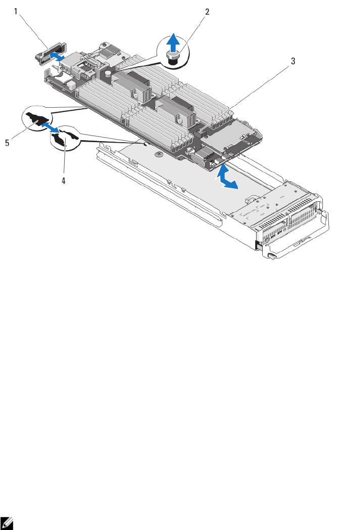
Figure 22. Removing and Installing the System Board
1. I/O connector cover
4. tabs on system chassis
2. retention latch
5. slots in system board tray
3. system board
Installing The System Board
1. Transfer the following components to the new system board:
– Internal USB key
– storage controller card/PCIe extender card
– SD vFlash card
– Memory modules and memory module blanks
– Processor(s) and heat sink(s), or processor filler blank
– network daughter card
2. Slide the new system board into the open end of the server module chassis until the retention latch or retention pin
engages.
NOTE: Ensure that the system board plate is parallel with the chassis.
When the board assembly is installed correctly, the tabs on the system board pan fit into the corresponding
openings in the floor of the server module chassis.
3. Replace the PCIe mezzanine card(s) in their original locations.
4. Reinstall the hard-drive/SSD backplane.
5. Replace the hard drive(s)/SSDs.
Ensure that you reinstall the hard drives/SSDs in their original locations.
55

6. Reinstall the cooling shroud.
7. Close the server module.
8. Remove the plastic I/O connector covers from the back of the server module.
9. Install the server module in the enclosure.
10. Import your new or existing iDRAC Enterprise license. For more information, see the
iDRAC7 User's Guide
at
dell.com/support/manuals.
NVRAM Backup Battery
Replacing The NVRAM Backup Battery
WARNING: There is a danger of a new battery exploding if it is incorrectly installed. Replace the battery only with
the same or equivalent type recommended by the manufacturer. Discard used batteries according to the
manufacturer's instructions. See the safety instructions that came with your system for additional information.
CAUTION: Many repairs may only be done by a certified service technician. You should only perform
troubleshooting and simple repairs as authorized in your product documentation, or as directed by the online or
telephone service and support team. Damage due to servicing that is not authorized by Dell is not covered by your
warranty. Read and follow the safety instructions that came with the product.
1. Remove the server module from the enclosure.
2. Open the server module.
3. Remove the system board to access the battery.
4. To remove the battery, press down firmly on the positive side of the connector and lift the battery out of the
securing tabs at the negative side of the connector.
5. To install a new system battery:
a) Support the battery connector by pressing down firmly on the positive side of the connector.
b) Hold the battery with the "+" facing up and slide it under the securing tabs at the positive side of the connector.
6. Press the battery straight down into the connector until it snaps into place.
7. Reinstall the system board.
8. Close the server module.
9. Install the server module in the enclosure.
10. Enter the System Setup to confirm that the battery is operating properly.
11. Enter the correct time and date in the System Setup's Time and Date fields.
12. Exit the System Setup.
13. To test the newly installed battery, remove the server module for at least an hour.
14. After an hour, reinstall the server module.
15. Enter the System Setup and if the time and date are still incorrect, see Getting Help.
56
Figure 23. Replacing the NVRAM Backup Battery
1. positive side of battery
2. negative side of battery connector
Storage Controller Card
Your system includes a dedicated expansion-card slot on the server module system board for a storage controller card
that provides the integrated storage subsystem for your system’s hard drives. The storage controller card supports SAS
and SATA hard drives. The storage controller card supports PCIe SSDs.
NOTE: The storage controller card is located underneath the hard-drive bays.
Removing The Storage Controller Card
CAUTION: Many repairs may only be done by a certified service technician. You should only perform
troubleshooting and simple repairs as authorized in your product documentation, or as directed by the online or
telephone service and support team. Damage due to servicing that is not authorized by Dell is not covered by your
warranty. Read and follow the safety instructions that came with the product.
1. Remove the server module from the enclosure.
2. Open the server module.
3. Remove the system board and place it on the work surface.
4. Remove the two screws from the storage controller card.
5. Pull the storage controller card straight up and out of the connector.
57
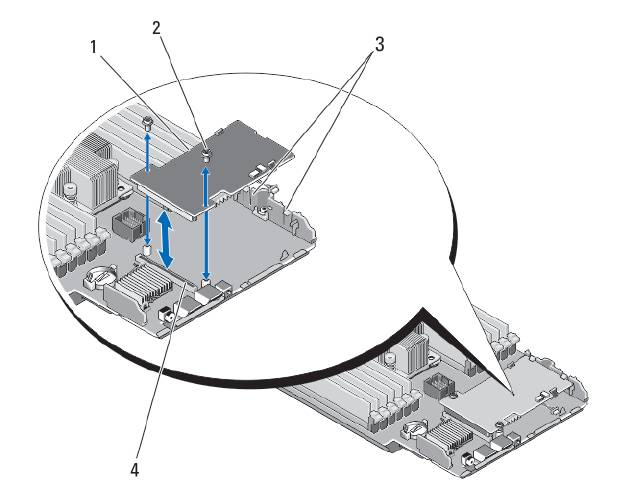
Figure 24. Removing and Installing the Storage Controller Card
1. storage controller card
2. screws (2)
3. tab
4. connector
Installing The Storage Controller Card
1. Holding by its edges, position the storage controller card so that the card-connector aligns with the system board
connector.
2. Adjust the other end of the card so that the card edge is secured under the two tabs on the plastic bracket.
3. Insert the controller card-connector firmly into the system board connector until the card is fully seated.
4. Install the two screws to secure the storage controller card to the server module system board.
5. Reinstall the system board.
6. Install the server module in the enclosure.
58
4
Troubleshooting Your System
Safety First—For You and Your System
CAUTION: Many repairs may only be done by a certified service technician. You should only perform
troubleshooting and simple repairs as authorized in your product documentation, or as directed by the online or
telephone service and support team. Damage due to servicing that is not authorized by Dell is not covered by your
warranty. Read and follow the safety instructions that came with the product.
NOTE: For troubleshooting information on the PowerEdge VRTX enclosure components, see “Troubleshooting The
Enclosure” in the
Dell PowerEdge VRTX Enclosure Owner's Manual
at dell.com/poweredgemanuals.
Troubleshooting System Memory
CAUTION: Many repairs may only be done by a certified service technician. You should only perform
troubleshooting and simple repairs as authorized in your product documentation, or as directed by the online or
telephone service and support team. Damage due to servicing that is not authorized by Dell is not covered by your
warranty. Read and follow the safety instructions that came with the product.
NOTE: Before performing the following procedure, ensure that you have installed the memory modules according
to the memory installation guidelines for the server module.
1. Restart the server module:
a) Press the power button once to turn off the server module
b) Press the power button again to apply power to the server module.
If no error messages appear, go to step 8.
2. Enter the System Setup and check the system memory setting.
If the amount of memory installed matches the system memory setting, go to step 8.
3. Remove the server module from the enclosure.
4. Open the server module.
CAUTION: The memory modules are hot to touch for some time after the server module has been powered
down. Allow time for the memory modules to cool before handling them. Handle the memory modules by the
card edges and avoid touching the components.
5. Reseat the memory modules in their sockets.
6. Close the server module.
7. Install the server module in the enclosure.
8. Run the appropriate diagnostic test. For more information, see Using System Diagnostics.
If the test fails, see Getting Help.
59
Troubleshooting Hard Drives
CAUTION: Many repairs may only be done by a certified service technician. You should only perform
troubleshooting and simple repairs as authorized in your product documentation, or as directed by the online or
telephone service and support team. Damage due to servicing that is not authorized by Dell is not covered by your
warranty. Read and follow the safety instructions that came with the product.
CAUTION: This troubleshooting procedure can destroy data stored on the hard drive. Before you proceed, back up
all the files on the hard drive, if possible.
1. Run the appropriate controllers test and the hard drive tests in system diagnostics.
If the tests fail, go to step 3.
2. Take the hard drive offline and wait until the hard-drive indicator codes on the drive carrier signal that the drive
may be removed safely, then remove and reseat the drive carrier in the server module.
3. Restart the server module, enter the System Setup and confirm that the drive controller is enabled.
4. Ensure that any required device drivers are installed and are configured correctly.
NOTE: Installing a hard drive into another bay may break the mirror if the mirror state is optimal.
5. Remove the hard drive and install it in the other drive bay.
6. If the problem is resolved, reinstall the hard drive in the original bay.
If the hard drive functions properly in the original bay, the drive carrier could have intermittent problems. Replace
the drive carrier.
7. If the hard drive is the boot drive, ensure that the drive is configured and connected properly.
8. Partition and logically format the hard drive.
9. If possible, restore the files to the drive.
If the problem persists, see Getting Help.
Troubleshooting USB Devices
CAUTION: Many repairs may only be done by a certified service technician. You should only perform
troubleshooting and simple repairs as authorized in your product documentation, or as directed by the online or
telephone service and support team. Damage due to servicing that is not authorized by Dell is not covered by your
warranty. Read and follow the safety instructions that came with the product.
1. Ensure that the server module is turned on.
2. Check the USB device connection to the server module.
3. Swap the USB device with a known-working USB device.
4. Connect the USB devices to the server module using a powered USB hub.
5. If another server module is installed, connect the USB device to that server module. If the USB device works with a
different server module, the first server module may be faulty. See
Getting Help.
60
