Dimplex SRX 180M: инструкция
Раздел: Бытовая, кухонная техника, электроника и оборудование
Тип: Кулер для воды
Инструкция к Кулеру для воды Dimplex SRX 180M
Dimplex SmartRad Fan Convector
SRX 080M, SRX 120M, SRX 140M & SRX 180M
EN
RU
DK
The product complies with the European Safety Standards EN60335-1 and the European Standard Electromagnetic Compatibility (EMC) EN55014, EN60555-2
and EN60555-3. These cover the essential requirements of EEC Directives 2006/95/EC and 2004/108/EC
FR
NO
DE
FI
NL
PL
srx_ba 01/11/C
362
38
100
180
30
125
MIN
590
MIN
535
150
MIN
150
MIN
235
MIN
100
MIN
(a)
(d)
(b)
(c)
J
A
E
B
F
C
G
D
H
K
1 2 3 4
82
A
B
C
D
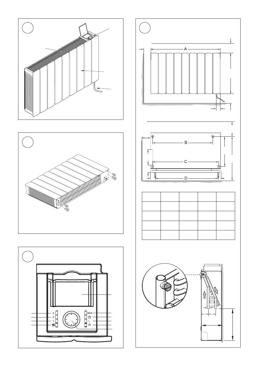
SRX 080
503
324
396
386
SRX 120
670
492
564
564
SRX 140
740
562
634
624
SRX 180
911
732
804
794
50
15
150
50
220
P
N
L1
P
N
L1
5 6
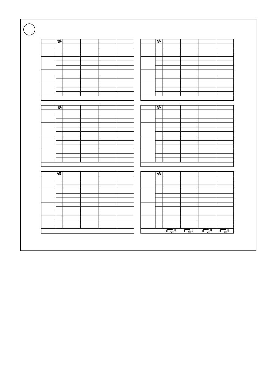
Power Output
35°C
45°C
55°C
65°C
35°C
45°C
55°C
65°C
3
1631
2734
3844
4959
3
1480
2502
3520
4546
2
1079
1803
2530
3260
2
1020
1713
2406
3102
1
641
1069
1499
1929
1
625
1044
1464
1885
3
1299
2177
3061
3951
3
1199
2024
2850
3682
2
838
1403
1968
2536
2
802
1346
1892
2439
1
493
823
1154
1484
1
484
808
1133
1459
3
1120
1878
2641
3408
3
1044
1760
2479
3202
2
719
1201
1686
2172
2
691
1160
1629
2100
1
415
693
971
1249
1
408
683
957
1231
3
759
1273
1790
2050
3
719
1210
1705
2203
2
479
801
1124
1448
2
465
780
1095
1412
1
251
419
588
756
1
249
416
582
749
35°C
45°C
55°C
65°C
35°C
45°C
55°C
65°C
3
1059
1832
2648
3498
3
852
1431
2020
2559
2
820
1408
2021
2655
2
695
1167
1647
2109
1
558
948
1346
1750
1
506
848
1175
1542
3
900
1558
2256
2984
3
752
1269
1798
2263
2
671
1151
1651
2167
2
591
995
1355
1793
1
442
749
1063
1378
1
411
691
955
1251
3
806
1394
2016
2668
3
689
1164
1557
2070
2
591
1010
1447
1894
2
530
894
1215
1606
1
379
641
907
1174
1
357
599
828
1083
3
587
1012
1460
1926
3
530
902
1190
1580
2
413
704
1005
1309
2
387
655
884
1163
1
237
399
564
728
1
231
387
534
694
35°C
45°C
55°C
65°C
35/30°C
45/40°C
55/47°C
65/50°C
3
551
918
1284
1649
3
1495
2856
3925
4628
2
487
812
1136
1460
2
893
1760
2424
2879
1
394
657
920
1183
1
522
1008
1395
1636
3
511
852
1193
1535
3
1078
2172
2982
3492
SRX120
SRX120
SRX180
SRX180
SRX140
SRX140
SRX80
SRX80
SRX180
SRX180
SRX140
SRX140
SRX120
SRX120
SRX80
SRX80
SRX180
SRX180
Q = 450 l/h
Q = 300 l/h
Q = 150 l/h
Q = 100 l/h
2
436
728
1020
1313
2
631
1329
1828
2154
1
338
564
791
1019
1
344
752
1039
1176
3
480
802
1124
1446
3
870
1826
2506
2924
2
402
672
943
1215
2
561
1119
1541
1770
1
302
504
707
912
1
331
621
856
1017
3
392
655
921
1191
3
573
1165
1595
1777
2
312
522
734
950
2
358
695
956
1137
1
207
345
486
627
1
201
375
516
607
Q
SRX120
SRX80
SRX80
SRX140
SRX140
Q = 50 l/h
SRX120
7
- 1 -
Dimplex SmartRad fan convector
Models: SRX 080M, SRX 120M, SRX 140M & SRX 180M
PLEASE STORE THESE INSTRUCTIONS IN A SAFE PLACE.
Important safety information
The air inlet and outlet guards must not be covered or
blocked.
Before performing maintenance work on the device, discon-
nect it from the power supply.
THE DEVICE MUST BE GROUNDED.
The heater must not be installed directly below a permanently
installed socket. Combustible materials or liquids and other
highly flammable furnishings must be kept away from the
heater.
For the necessary minimum distances (in mm), see fig. 4.
Install the device such that it is not possible for someone in
the bath or shower to touch the control elements.
The heater must not be operated in very dusty areas.
This device is not suitable for children or persons who cannot
use the device safely as a result of physical or mental disability
or reduced perception without the assistance or supervision
of another person. Children should be supervised to ensure
they do not play with the device.
A warning symbol is attached to the heater. This in-
dicates that the device must not be covered.
The operating instructions belong to the device and
must be stored in a safe place. In case of the owner changes,
the operating instructions should be passed on to the new
owner.
IMPORTANT – If the mains cable of the device is damaged, it
must be replaced by the manufacturer, a customer service
representative or a similarly qualified person.
Always ensure proper operation.
Device description
The SmartRad model is a fan convector for heating living spaces.
The fan convector is intended for connection to a central heat-
ing system. The fan convector is suitable for use in heat pump
systems, but it can also be operated in conjunction with other
heating systems, e.g. with oil or gas fires. The device draws in air
from the underside. This is heated up in the heat exchanger and
discharged at the top.
Fig. 1:
(a) Casing cover
(b) Control panel
(c) Air outlet guard
(d) 1 m connection cable
Fan convectors may only be used in central heating systems
with a closed control circuit.
The heating system must be operated as a dual-pipe system.
The devices must be of a sufficient rating such that they can
compensate for heat losses in the room.
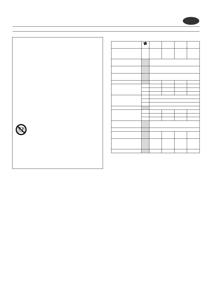
Technical data
SRX
080M
SRX
120M
SRX
140M
SRX
180M
Heat output (kW) at
flow temperature of
45°C
2
0.70
1.10
1.40
1.80
Temperature range
of flow temperature (°C)
25 – 85
Maximum permissible
flow temperature (°C)
85
Permissible operating
overpressure (MPa)
1
Pressure drop (kPa)
11.3
13.1
13.7
15.8
Air volume flow (m³/h)
3
228
345
410
540
2
125
190
225
300
1
60
100
120
160
Sound pressure level at
1 m (dB(A))
3
47
2
38
1
27
Nominal voltage
~ 230 V, 50 Hz
Power consumption
of fan (W)
3
26
43
56
50
2
19
29
36
33
1
16
20
24
23
Standby energy
consumption (W)
< 1
Protection category
IP 20
Volume of
heat exchanger (ml)
310
430
480
600
Dimensions
W x H x D (mm)
503 x
530 x
145
670 x
530 x
145
740 x
530 x
145
911 x
530 x
145
Weight (kg)
12
15
17.5
22
Installation preparation
Remove packaging material.
Unscrew the four fixing screws from underside of device (see
fig. 2) to remove casing cover. Store the casing cover such that it
cannot be damaged during installation.
Fixing to the wall
For drywalls, use suitable fixing material (not supplied)!
Draw and drill four holes on a sturdy wall as shown in fig. 4. All
dimensions are in mm.
Insert dowels and pre-fit the two top screws (don't completely
screw in yet). Hang device on the two top screws.
Insert and tighten the two bottom screws, then tighten the two
top screws.
Hydraulic connection
To ensure a sufficient heating water flow rate through the fan
convectors, observe the following points:
-
The devices are not suitable for installation in single-pipe
systems.
-
The nominal width of the connection pipe must have a
minimum diameter of 15 mm.
-
If the devices are installed in a heating system with various
heat distribution systems (e.g. underfloor heating), a sepa-
rate circuit is required to guarantee a sufficient water flow
rate.
-
For optimum operation (heat output) of the fan convectors,
EN
- 2 -
a hydraulic balance is required on the heating system.
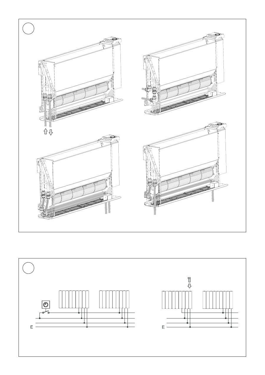
Fig. 5 shows the various hydraulic connection options on the
device. The recommended flow and return connections are
shown in fig. 5 and fig. 4 (below). The heating pipes can be laid
in the floor or in the wall. The device is supplied with two cop-
per pipes with a diameter of 15 mm that are fitted on the heat
exchanger at the factory.
Before and during filling of the heating system, all pipe connec-
tions must be checked for leaks. During filling, the bleeder valve
(see fig. 4) must be open such that air can escape from the de-
vice. If necessary, bleed again following commissioning (circulat-
ing pump running).
Electrical connection
WARNING: The device must be grounded.
WARNING – phase conductor (brown) and neutral conductor
(blue) must not be swapped as this may cause malfunctions.
The electrical connection should have a supply voltage of ~230-
240V, 50 Hz.
The device must be installed by a qualified electrician in compli-
ance with the existing standards and local installation guide-
lines. Before performing installation, ensure that the power
supply is switched off.
The device is equipped with a flexible 1 m connection cable (4 x
0.75 mm²), which can be used to connect the heater directly to
the power supply via a suitable wall socket.
In the electrical supply line, fit a circuit breaker for each pole
with a contact opening width of at least 3 mm. Automatic fuses
are also permitted as separators. Automatic fuses should have a
delayed tripping characteristic.
Conductor configuration of the connection cable:
Brown: 'L' – supply voltage phase conductor
Blue: 'N' – supply voltage neutral conductor
Green/yellow: 'PE' grounding conductor
Black: control conductor (temperature reduction; on/off)
For circuit diagram, see fig. 6.
Control conductor
The black control conductor has the following functions:
Lowering temperature using an external timer or switch
By activating the control conductor, see fig. 6 on the left, the set
target temperature on the device is lowered.
The temperature reduction is forwarded to any downstream
devices via the control conductor.
Operation with programming cassette
The control signals of the programming cassette, which is
plugged into the pilot device, are forwarded to any downstream
devices via the control conductor, see fig. 6 on the right.
The control conductor does not have to be in phase with the
supply connection. If the control conductor is not used, it must
be properly insulated.
WARNING – if you switch over to controlled operation, the
mains voltage is on this conductor!
WARNING – do not ground the control conductor.
When taking out of service, e.g. for maintenance work, ensure
that both the mains supply and the control conductor are dis-
connected from the power supply, because this may result in
external voltage (via a timer contact or pilot device with pro-
gramming cassette).
Final installation
Fit casing cover following completion of installation work. To do
this, screw in the four fixing screws on the underside of the de-
vice, see fig. 2.
Operation
The control panel is shown in fig. 3.
The individual elements have the following meaning:
A – Operating mode button
B – On/off indicator
C – Manual mode indicator
D – Automatic mode indicator
E – Fan level button
F – Low fan level indicator
G – Medium fan level indicator
H – High fan level indicator
J – Thermostat setting wheel
K – Cover for programming cassette slot
Manual operation
Press the
button once or several times until the yellow
indicator lights up.
Press the
button once or several times to select the de-
sired fan level (fan speed). The set fan level is indicated by
the red indicator (1, 2, 3). Set the desired room tempera-
ture with the knob. The set fan level is switched on and off
depending on the room temperature. The temperature re-
duction is forwarded to any downstream devices via the control
conductor.
Automatic mode (eco)
Press the
button once or several times until the red
eco
indicator lights up.
Set the desired room temperature with the knob. Depend-
ing on the current room temperature and the target tem-
perature set on the thermostat, the electronics calculate
which of the three fan levels (fan speeds) to use. The elec-
tronics select the required fan level depending on the dif-
ference between the current room temperature and the de-
sired target temperature.
If necessary, the number of possible fan levels can be reduced.
For instance, to limit the fan levels to a maximum of 2, press
the
button once or several times until the red
2
indicator
lights up.
Operation with a programming cassette or a timer can only take
place in automatic mode (eco). If there is a control signal, the
green
eco
indicator lights up.
Fault indication
If the water temperature is too low, operation of the device is
interrupted and the red
indicator flashes. In this case, check
that the heating system and circulating pump are operating cor-
rectly. For more information, please refer to the "Troubleshoot-
ing" chapter.
- 3 -
Operation with air/water heat pumps
When operating with an air/water heat pump, particularly when
temperatures are low outside, the heat pump's buffer tank
must be at a temperature of at least 14°C to ensure that the
heat pump evaporator can defrost. You should therefore en-
sure that thawing has taken place if necessary before opening
the valves to the heating circuit.
Troubleshooting
The following causes can result in the fan convector producing
insufficient heat:
•
Red indicator flashes:
See "Fault indication" section
•
Air trapped in heat exchanger:
Disconnect device from power supply, remove casing and
bleed heat exchanger. For position of bleeder screw, see fig.
4.
•
Water temperature too low:
Set flow temperature higher on heating system.
•
Insufficient water flow rate through device:
Adjust flow rate (hydraulic balance). To do this, close ther-
mostat valves on the other heaters.
•
Dirt on heat exchanger:
Clean heat exchanger, see "Maintenance" section.
Cleaning outer surfaces
The heater must be switched off and cooled for cleaning. The
surfaces of the heater can be cleaned by wiping with a soft,
damp cloth and then dried. Do not use abrasive powder or fur-
niture polish to clean as these may damage the surface.
Maintenance – to be performed by a specialist
Dust or lint that collects inside the heater must be removed at
regular intervals.
To do this, disconnect the device from the power supply, loosen
the 4 fixing screws on the underside of the casing and carefully
remove the casing cover. Remove dirt with a soft brush or a
vacuum cleaner.
Build-up of air in the heat exchanger can be remedied by open-
ing the bleeder valve (fig. 4).
Warranty
We offer a two-year warranty for this device in accordance with
our warranty conditions.
Glen Dimplex Deutschland GmbH
Phone +49 9221 709564
Am Goldenen Feld 18
Fax +49 9221 709589
D-95326 Kulmbach
www.glendimplex.de
Subject to modifications
EN 01/11/C
