Pioneer CDJ-400: CONNECTIONS 2. Connecting control cable for relay play
CONNECTIONS 2. Connecting control cable for relay play: Pioneer CDJ-400
Table of contents
- IMPORTANT VENTILATION CAUTION Operating Environment
- FEATURES
- BEFORE OPERATING (FEATURES) CONTENTS
- DISCS USABLE WITH THIS UNIT Types of discs playable on this unit Playing MP3 files
- BEFORE OPERATING (DISCS USABLE WITH THIS UNIT)
- CAUTIONS REGARDING HANDLING Location Storing Discs Installation Guidelines Condensation Cleaning and Handling Compact Discs Cleaning the Player CD Lens Cleaner
- CONNECTIONS 2. Connecting control cable for relay play
- 3. Connecting to other devices 4. Connecting the power cord
- PANEL FACILITIES 7. HOLD button
- 30. Jog touch indicators Rear Panel
- About TEXT display Removing the jog sheet
- DISC LOADING/UNLOADING
- DJ PLAYER OPERATIONS Starting playback Auto cue function Resume function To stop playback To temporarily interrupt playback
- Track cueing Jog dial functions Rotary search Fast-forward/fast-reverse
- Scratch Jog Effect Digital Jog Break Change playback speed Applying master tempo
- Mixing different tracks Cue point settings
- ADVANCED OPERATIONS Fader start playback Loop playback Scratch play Spin play Reverse play
- Relay play using two players Cue point/loop point memory Writing and reading data
- MIDI SETTING
- TROUBLESHOOTING Symptom
- Error message display
- SPECIFICATIONS
BEFORE OPERATING (CONNECTIONS)
CONNECTIONS
Before making or changing connections, switch off the power and disconnect the power cord from the AC outlet.
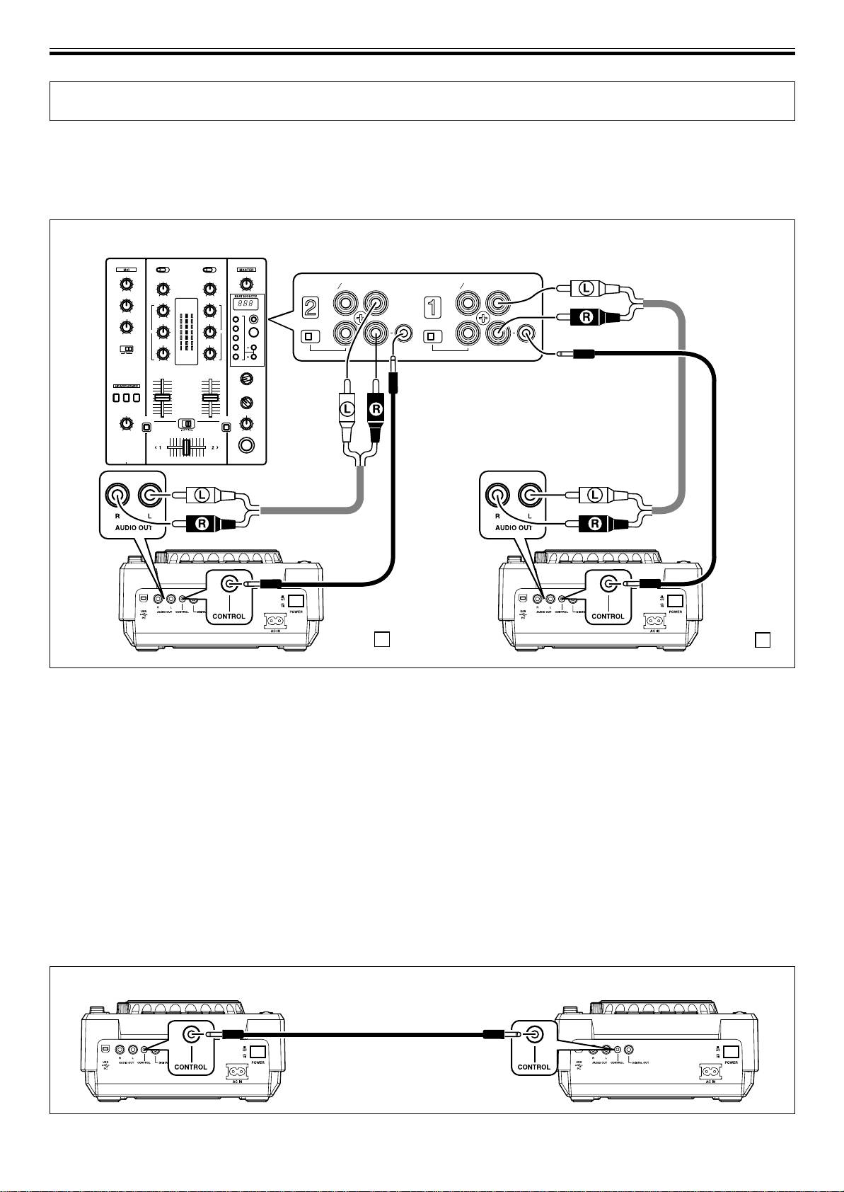
1. Connection to a Pioneer DJ mixer (audio output and CONTROL connector)
Using the supplied audio cables, connect the white plug into the L (left) terminal and the red plug to the R (right) terminal.
Connect the supplied control cable to enable control of the unit from the mixer for fader start play and back cue.
When connecting to a DJ mixer (DJM-400)
DJM-400
PHONO
PHONO
LINE
CD
LINE
CD
L
L
LINE PHONO
LINE PHONO
R
R
CONTROL
CONTROL
Supplied
control
cable
Supplied audio
cable
Supplied
Supplied
audio cable
control cable
CDJ-400 B
CDJ-400 A
÷ When connecting to DJM-600, DJM-300 and DJM-500, connect as shown in the accompanying illustration.
÷ When connecting to DJM-909 and DJM-707, connect CH-1 CD with A PLAYER, CH-2 CD with B PLAYER using the supplied
audio cables.
÷ When connecting to DJM-3000, connect A PLAYER to LINE 1 of CH-1, and B PLAYER to LINE 3 of CH-2.
÷ When connecting to the DJM-1000, use the supplied audio cable to connect one set of the CD/LINE connectors to PLAYER A
and the other CD/LINE connectors to PLAYER B. For digital audio signal output, use a coaxial digital signal cable (sold
separately) to connect the CDJ-400’s DIGITAL OUT connector to one of the DJM-1000’s DIGITAL IN connectors (channel 4 to 6).
÷ When connecting to the DJM-800, use the supplied audio cable to connect one set of the CD/LINE connectors to PLAYER A and
the other set of CD/LINE connectors to PLAYER B. For digital output of audio signals, use a coaxial digital signal cable (sold
separately) to connect the CDJ-400’s DIGITAL OUT connector to the DJM-800’s DIGITAL IN connector.
÷ When connecting to the DJM-700, use the supplied audio cable to connect one set of CD/LINE connectors to PLAYER A and the
other set of CD/LINE connectors to PLAYER B.
÷ When connecting to a audio mixer other than the ones listed above, connect the unit’s AUDIO OUT terminal to the mixer’s line
in terminal, or the AUX terminal (* do not connect to the PHONO terminal, since distortion or improper operation may occur).
2. Connecting control cable for relay play
Alternating playback can be automatically performed when the CONTROL connectors of the two units are connected with the
supplied control cable. (☞P.19)
CDJ-400 CDJ-400
Supplied control cable
8
<DRB1451>
En


