Yamaha RX-797: CONTROLS AND FUNCTIONS
CONTROLS AND FUNCTIONS: Yamaha RX-797
CONTROLS AND FUNCTIONS
CONTROLS AND FUNCTIONS
INTRODUCTION
Front panel
ZONE 2 ON/OFF
FM/AM
l
TUNING
h
CD DIRECT AMPPURE DIRECT
ZONE CONTROL
EDIT
MEMORY
TUNING MODE
MAN'L/AUTO FM
AUTO/MAN'L
MASTER SPEAKERS
BA
A/B/C/D/E
12345678
VOLUME
12
ON OFF
INPUT
REC OUT
BASS
TREBLE
BALANCE
LOUDNESS
MAIN ZONE
SOURCE
PHONES
MD/TAPE
CD
1
0
1
1
0
1
1
0
1
1
FLAT
VCR TUNER
22
22
22
210
–
30dB
ON/OFF
DTV/CBL
PHONO
3
3
3
3
3
3
3 9
DVD
44
44
44
48
–
55
+
–
55
+
L
55
R
57
0
6
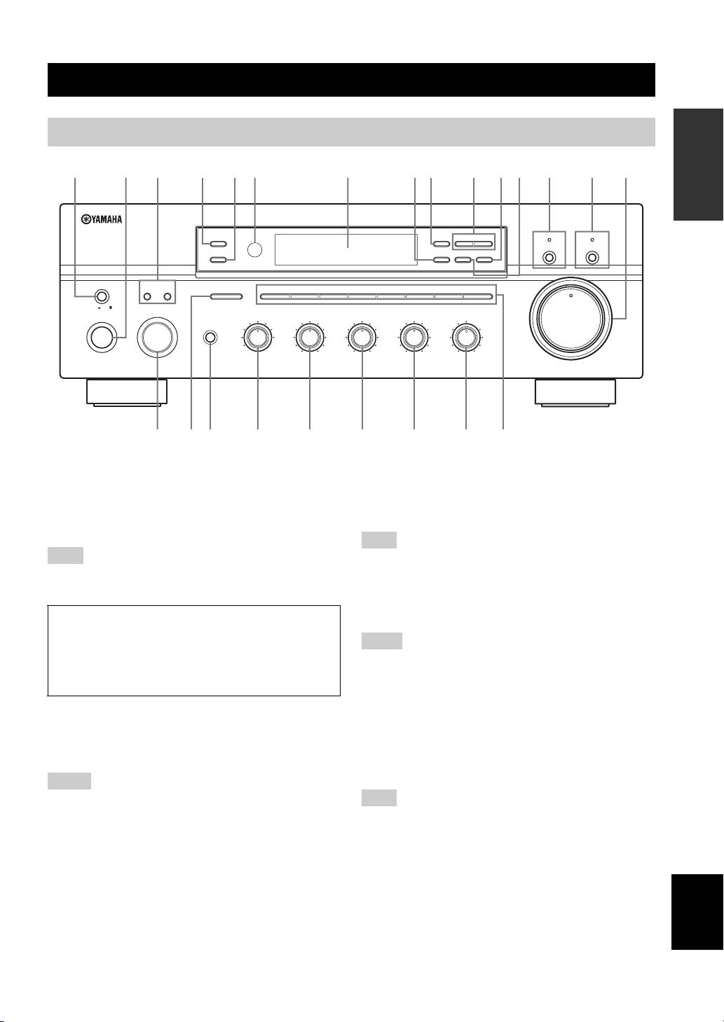
1 MASTER ON/OFF
4 ZONE 2 ON/OFF
Press inward to the ON position to turn on the power of
Turns on Zone 2 or set it to the standby mode. When Zone
this unit. Press again to release it outward to the OFF
2 is turned on, signals are output at the ZONE 2 OUT
position to turn off this unit.
jacks.
See page 16 for details.
This switch is operational only when MASTER ON/OFF is
Even when this unit is turned off, this unit consumes a small
pressed inward to the ON position.
amount of power to preserve the memory.
5 ZONE CONTROL
Press to control the input source of Zone 2.
• This button is operational only when Zone 2 is turned on.
• When you press this button, the ZONE 2 indicator flashes in the
front panel display for approximately 5 seconds. Select the
input source of Zone 2 while the indicator is flashing.
2 MAIN ZONE ON/OFF
• You can select the preset station when TUNER is selected as the
Turns on Main Zone of this unit or sets it to the standby
input source of Zone 2.
mode.
See page
16
for details.
6 Remote control sensor
Receives infrared signals from the remote control.
• This switch is operational only when MASTER ON/OFF is
pressed inward to the ON position.
Switch the remote control ID between ID1 and ID2 when using
• In the standby mode, this unit consumes a small amount of
multiple YAMAHA receivers or amplifiers (see pages 9, 32 and
power to receive infrared signals from the remote control.
33).
3 SPEAKERS A/B
7 Front panel display
Turns on or off the speaker set connected to the
English
Shows information about the operational status of this
SPEAKERS A and/or SPEAKERS B terminals on the rear
unit.
panel each time the corresponding button is pressed (see
page 17).
3
12
20
8
4
2
∞
20
60
60
26
26
40
40
16
16
-dB
-dB
6312 5498AB7DC0
E
DISPLAY
(General model)
HGFIJKLMN
Note
Note
Memory back-up
The memory back-up circuit prevents the stored data
Notes
from being lost. However, the stored data will be lost if
the power cord is disconnected from the AC wall outlet
for more than one week.
Notes
Note

CONTROLS AND FUNCTIONS
8 EDIT
F INPUT selector
Exchanges the assignment of two preset stations with each
Selects the input source you want to listen to or watch.
other when TUNER is selected as the input source (see
G A/B/C/D/E
page 28).
Selects the preset station group (A to E) when TUNER is
9 FM/AM
selected as the input source (see page 26).
Switches the reception band between AM and FM when
H PHONES jack
TUNER is selected as the input source (see page 23).
Outputs audio for private listening with your headphones.
0 TUNING l / h
Note
Selects the tuning frequency when TUNER is selected as
the input source (see page 23).
Press SPEAKERS A/B so that the SP A/B indicators turn off
before you connect your headphones to the PHONES jack.
A TUNING MODE
Switches the tuning mode between automatic (the AUTO
I REC OUT selector
indicator turns on as a result) and manual (the AUTO
Selects a source for recording to the MD recorder or the
indicator turns off as a result) when TUNER is selected as
tape deck independently of the INPUT selector setting,
the input source.
allowing you to record the selected source while listening
to another source (see page 20).
B MEMORY
Stores a station in the system memory (see page 27).
J BASS
Sets this unit to the automatic preset tuning mode (see
Increases or decreases the low frequency response. The 0
page 25).
position produces a flat response (see page 19).
C PURE DIRECT and indicator
K TREBLE
Allows you to listen to a source in the purest possible
Increases or decreases the high frequency response. The 0
sound. The indicator above it lights up when this function
position produces a flat response (see page 19).
is turned on.
L BALANCE
See page 19 for details.
Adjusts the sound output balance of the left and right
D CD DIRECT AMP and indicator
speakers to compensate for sound imbalances caused by
Allows you to listen to a CD source in the purest possible
speaker locations or listening room conditions (see page
sound. The indicator above it lights up and the front panel
19).
display turns off when this function is turned on.
M LOUDNESS
See page 19 for details.
Retains a full tonal range at any volume level to
E VOLUME
compensate for the human ears’ loss of sensitivity to high
Increases or decreases the sound output level.
and low-frequency ranges at a low volume level (see page
19).
Note
N Preset station number buttons
This does not affect the OUT (REC) level.
(1 to 8)
Selects the preset station number (1 to 8) directly when
TUNER is selected as the input source (see page 28).
4

CONTROLS AND FUNCTIONS
Front panel display
INTRODUCTION
SP
DVD VCR CD TUNER PHONO
DTV/CBL
MD/TAPE
A B
ZONE2 ZONE3 MEMORY AUTO
TUNED STEREO
SLEEP
MUTE
HOLDPTY
EON
PS
PTY
RT
CT
1 SP (SPEAKERS) A/B indicators
7 SLEEP indicator
Light up according to the set of speakers selected.
Lights up when the sleep timer is turned on.
Both indicators light up when both sets of speakers are
8 MUTE indicator
selected.
Flashes while the MUTE function is turned on.
2 ZONE 2 indicator
9 Multi-information display
Lights up when Zone 2 is turned on.
Shows information when adjusting or changing settings.
3 Input source indicators
0 TUNED indicator
Light up when this unit is in the corresponding mode.
Lights up when this unit is tuned into a station.
4 MEMORY indicator
■ Europe model only
Flashes for approximately 5 seconds after MEMORY on
the front panel is pressed. While the MEMORY indicator
A Radio Data System indicators
is flashing, store the displayed station in the system
The box-shaped indicator beside the name of each Radio
memory by using A/B/C/D/E and one of the preset station
Data System mode lights up when the corresponding
number buttons on the front panel.
Radio Data System mode is selected.
5 AUTO indicator
PTY HOLD indicator
Lights up when this unit is in the automatic tuning mode.
Lights up while searching for stations in the PTY
6 STEREO indicator
SEEK mode.
Lights up when this unit is receiving a strong signal for an
EON indicator
FM stereo broadcast while the AUTO indicator is lit.
Lights up when the Radio Data System station that
offers the EON data service is being received.
English
5
0A9
12 4 5 6 738
CONTROLS AND FUNCTIONS
Rear panel
123 5
4
6
(General model)
TUNER
REMOTE
AC IN
DVD
DVD
IN
GND
1
DTV/
DTV/
CBL
CBL
OUT
AM
ANT
IN
2
AC OUTLETS
VOLTAGE
IN
IN
SWITCHED
CONTROL OUT
SELECTOR
VCR
VCR
+12V 15mA MAX.
SPEAKERS
IMPEDANCE SELECTOR
OUT
OUT
COUPLER
SET BEFORE POWER ON
75Ω
UNBAL.
FM
ANT
MAIN
IN
GND
MONITOR
(PLAY)
IN
OUT
A
CD
MD/
PRE
TAP E
OUT
ZONE 2
OUT
A OR B: 4ΩMIN. /SPEAKER
A OR B: 6ΩMIN. /SPEAKER
OUT
(REC)
A+B: 8ΩMIN. /SPEAKER
A+B:12ΩMIN. /SPEAKER
PHONO
SUB
WOOFER
B
VIDEO
ZONE 2
OUT
OUTPUTAUDIOAUDIO
70 CD8AB
9
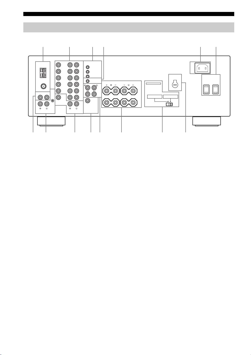
1 Antenna terminals
8 PHONO jacks and GND terminal
Connect FM and AM antennas.
Connect a turntable.
See page 13 for connections information.
See page 12 for connection information.
2 AUDIO/VIDEO jacks
9 ZONE 2 jacks
Connect audio and video components.
Connect a Zone 2 component.
See page 12 for connection information.
See page 34 for connection information.
3 REMOTE jacks
0 SUBWOOFER OUTPUT jack
These jacks are used to input/output remote control
Connect a subwoofer with built-in amplifier.
signals.
A COUPLER jacks
See page 34 for connection information.
Connect an external unit.
4 CONTROL OUT jack
See page 15 for connection information.
This is a control expansion jack. Consult your nearest
B SPEAKERS terminals
authorized YAMAHA dealer or service center about this
Connect speakers.
jack.
See page 11 for connection information.
5 AC IN
C IMPEDANCE SELECTOR switch
Use to plug in the supplied power cable.
Switches the impedance setting.
See page 15 for connection information.
See page 15 for details.
6 AC OUTLET(S) (SWITCHED)
■ Asia and General models only
Use to supply power to your other audio and video
components.
D VOLTAGE SELECTOR
See page 15 for details.
See page 15 for details.
7 CD jacks
Connect a CD player.
See page 12 for connection information.
6
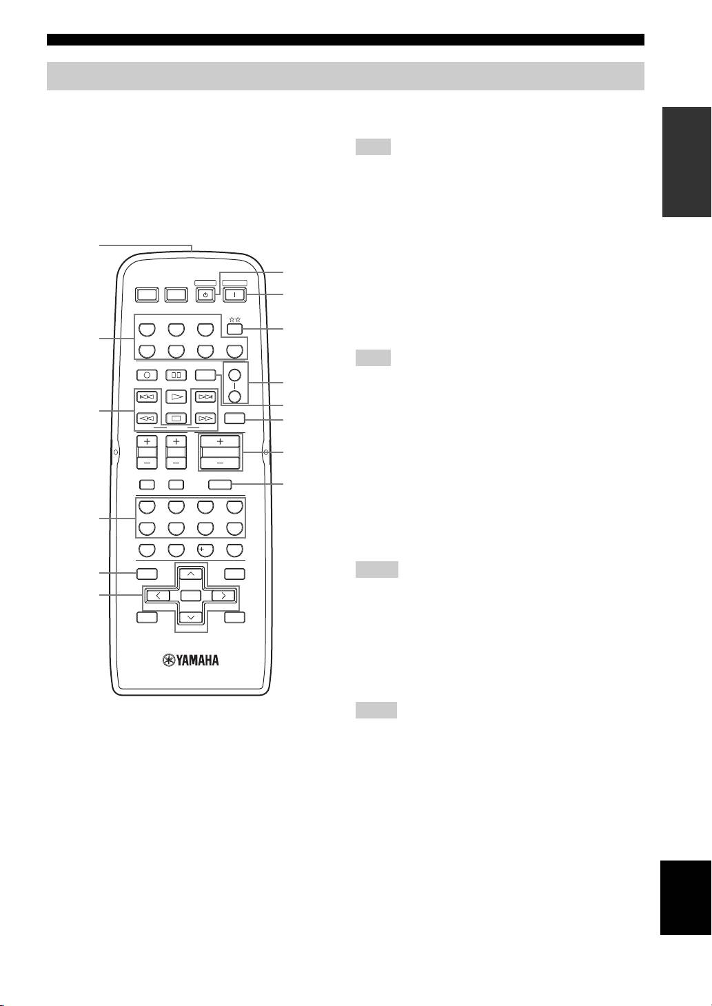
CONTROLS AND FUNCTIONS
Remote control
This section describes the function of each button on the
3 Radio Data System control buttons
INTRODUCTION
remote control used to control this unit or other
Controls the Radio Data System features.
components made by YAMAHA or other manufacturers.
The functions of the buttons used to control your other
Note
audio and video components are the same as those of the
The Radio Data System features (FREQ/TEXT, EON, PTY
corresponding buttons on those components. Refer to
SEEK MODE and PTY SEEK START) are only applicable to the
those components’ instruction manuals for details. To
Europe model and are operational only when TUNER is selected
operate other components using this remote control, see
as the input source. For details, see “Receiving Radio Data
“REMOTE CONTROL FEATURES” on page 36.
System stations” on page 29.
1
4 Numeric buttons (1 to 8)
Select the preset station number (1 to 8) when TUNER is
7
POWER POWER
STANDBY
POWER
selected as the input source.
AVTV
8
5 BAND
CD
MD/TAPE
TUNER
Switches to the previously used reception band (FM or
9
AM) when TUNER is selected as the input source.
2
DTV/CBL
VCR
PHONODVD
Note
REC
CODE SET
SPEAKERS
A
DISC SKIP
0
The frequency of the previously received station is automatically
B
recalled.
FREQ/TEXT
EON
SLEEP
A
3
B
6 A/B/C/D/E j / i
MODE PTY SEEK
START
Selects the preset station group (A to E) when TUNER
TV VOL
TV CH
VOLUME
C
is selected as the input source (see page 28).
TV MUTE TV INPUT
PRESET/CH u / d
MUTE
D
Selects the preset station number (1 to 8) when
4321
TUNER is selected as the input source (see page 28).
4
65
7
8
7 STANDBY
09
10
ENT.
Sets this unit to the standby mode.
5
MENUTITLE
Notes
BAND
6
ENTER
• This button is operational only when MASTER ON/OFF on the
A/B/C/D/E A/B/C/D/E
front panel is pressed inward to the ON position.
DISPLAYRETURN
• In the standby mode, this unit consumes a small amount of
PRESET/CH
power to receive infrared signals from the remote control.
• This button does not set Zone 2 to the standby mode.
8 POWER
Turns on this unit.
(Europe model)
Notes
1 Infrared signal transmitter
• This button is operational only when MASTER ON/OFF on the
front panel is pressed inward to the ON position.
Sends infrared signals.
• This button does not turn on Zone 2.
2 Input selector buttons
Select the desired input source and change the control area
(see page 36).
English
7

CONTROLS AND FUNCTIONS
9
Changes the control area (see page 36).
0 SPEAKERS A/B
Turns on or off the set of speakers connected to the
SPEAKERS A and/or SPEAKERS B terminals on the rear
panel of this unit when the corresponding button is
pressed each time.
A CODE SET
Use to set up remote control codes (see page 38).
B SLEEP
Sets the sleep timer.
C VOLUME +/–
Increases or decreases the sound output level.
Notes
• This does not affect the OUT (REC) level.
• When you press VOLUME +/– to control the sound output
level of this unit, VOLUME on the front panel rotates.
D MUTE
Mutes the sound output. Press again to restore the sound
output to the previous volume level (see page 22).
Note
The sound output to Zone 2 is not muted.
8
CONTROLS AND FUNCTIONS
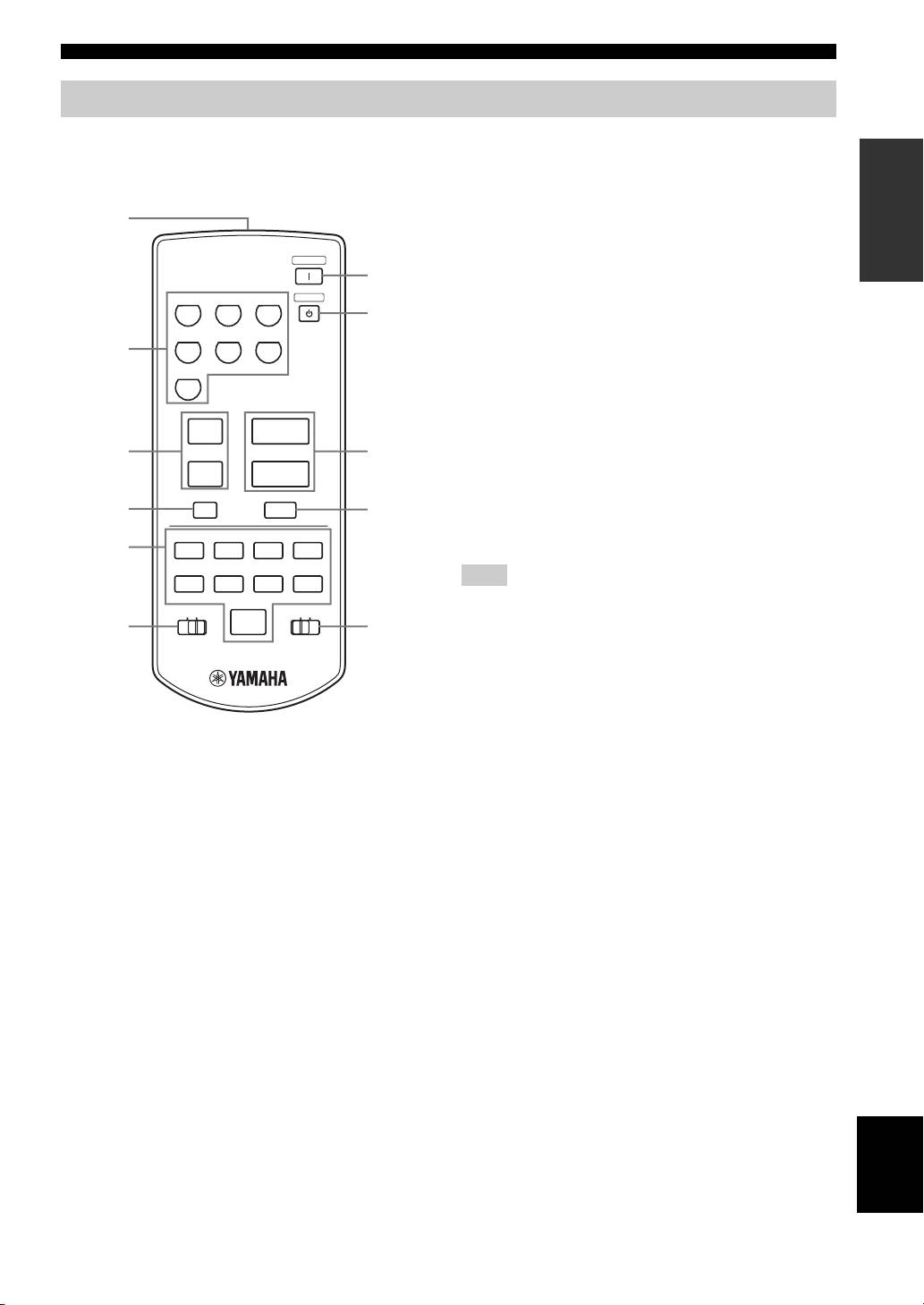
Zone 2 remote control
This section describes the function of each button on the
3 PRESET u / d
INTRODUCTION
Zone 2 remote control used to control Zone 2. You can
Selects the preset station number (1 to 8) when TUNER is
also use the Zone 2 remote control to control YAMAHA
selected as the input source.
CD players and YAMAHA cassette tape deck.
4 A/B/C/D/E
1
Selects the preset station group (A to E) when TUNER is
selected as the input source.
POWER
ZONE 2
7
5 CD/TAPE control buttons
CD PHONO
TUNER
STANDBY
Controls YAMAHA CD players or YAMAHA cassette
8
tape deck.
MD/TAPE VCR DTV/CBL
2
6 ID1/ID2 switch
Switches the remote control ID between ID1 and ID2 (see
DVD
page 33).
7 POWER
u
+
Turns on Zone 2.
3
PRESET
VOLUME
9
8 STANDBY
d
–
Sets Zone 2 to the standby mode.
A/B/C/D/E
4
MUTE
0
9 VOLUME +/–
A/B
Increases or decreases the sound output level of Zone 2.
5
w
e
f
DISPLAY
DIR BDIR A
REC
Note
b
s
a
DISC
This does not affect the OUT (REC) level.
TAPECDID2ID1
p
6
A
0 MUTE
Mutes the sound output to Zone 2. Press again to restore
the sound output to the previous volume level.
A CD/TAPE switch
(Europe model)
Switches the function of the control buttons numbered 5
between controlling YAMAHA CD players and
1 Infrared signal transmitter
controlling YAMAHA cassette tape deck.
Sends infrared signals.
2 Input selector buttons
Select the desired input source of Zone 2.
English
9
CONTROLS AND FUNCTIONS
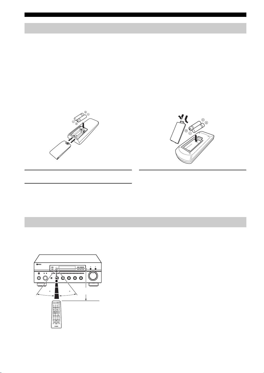
Installing batteries in the remote controls
■ Notes on batteries
• Change all of the batteries if the operation range of the remote controls decreases.
• Use AA, R6, UM-3 batteries for the remote control and AAA, R03, UM-4 batteries for the Zone 2 remote control.
• Make sure that the polarities are correct. See the illustration inside the battery compartment of each remote control.
• Remove the batteries if the remote controls are not used for an extended period of time.
• Do not use old batteries together with new ones.
• Do not use different types of batteries (such as alkaline and manganese batteries) together. Read the packaging carefully as these
different types of batteries may have the same shape and color.
• We strongly recommend using alkaline batteries.
• If the batteries have leaked, dispose of them immediately. Avoid touching the leaked material or letting it come into contact with
clothing, etc. Clean the battery compartment thoroughly before installing new batteries.
• Do not throw away batteries with general house waste; dispose of them correctly in accordance with your local regulations.
Remote control Zone 2 remote control
1
3
2
1
2
3
1 Open the battery compartment cover.
3 Close the cover back.
2 Insert the supplied batteries in each remote
control according to the polarity markings (+
and –) on the inside of the battery
compartment.
Using the remote controls
The remote controls transmit a directional infrared beam.
Be sure to aim the remote controls directly at the remote control sensor on the front panel of this unit or on the infrared
signal receiver in Zone 2 during operation.
■ Handling the remote controls
• The area between the remote controls and this unit (or the
infrared signal receiver in Zone 2) must be clear of large
ZONE 2 ON/OFF
FM/AM
l
TUNING
h
ZONE CONTROL
EDIT
MEMORY
TUNING MODE
CD DIRECT AMPPURE DIRECT
obstacles.
MAN'L/AUTO FM
AUTO/MAN'L
MASTER SPEAKERS
BA
A/B/C/D/E
12345678
VOLUME
ON OFF
• Do not spill water or other liquids on the remote controls.
MAIN ZONE
INPUT
PHONES
MD/TAPE
REC OUT
SOURCE
CD
1
BASS
0
1
TREBLE
BALANCE
VCR TUNER
22
22
1
0
1
22
1
0
1
LOUDNESS
1
FLAT
–
30dB
ON/OFF
DTV/CBL
DVD
PHONO
3
44
3
3
44
3
3
44
3
3
210
9
• Do not drop the remote controls.
–
55
+
–
55
+
L
55
R
48
57
6
• Do not leave or store the remote controls in the following types
of conditions:
Approximately 6 m (19.7 ft)
30 30
– places of high humidity, such as near a bath
– places of high temperature, such as near a heater or a stove
POWER POWER
AVTV
STANDBY
POWER
CD
MD/TAPE
TUNER
– places of extremely low temperatures
DTV/CBL
VCR
PHONODVD
REC
CODE SET
SPEAKERS
DISC SKIP
A
FREQ/TEXT
EON
SLEEP
B
– dusty places
MODE PTY SEEK
START
TV VOL
TV CH
VOLUME
TV MUTE TV INPUT
MUTE
• Do not expose the remote control sensor to strong lighting, in
4321
65
7
8
09
10
ENT.
particular, an inverter type fluorescent lamp; otherwise, the
BAND
MENUTITLE
A/B/C/D/E A/B/C/D/E
ENTER
PRESET/CH
DISPLAYRETURN
remote controls may not work properly. If necessary, position
this unit away from direct lighting.
10
Оглавление
- CAUTION: READ THIS BEFORE OPERATING YOUR UNIT.
- CONTENTS
- FEATURES
- CONTROLS AND FUNCTIONS
- CONNECTIONS
- PLAYING AND RECORDING
- FM/AM TUNING
- RADIO DATA SYSTEM (EUROPE MODEL ONLY)
- ADVANCED SETUP
- ZONE 2
- REMOTE CONTROL FEATURES
- TROUBLESHOOTING
- SPECIFICATIONS
- ATTENTION: VEUILLEZ LIRE CE QUI SUIT AVANT D’UTILISER L’APPAREIL.
- TABLE DES MATIÉRES
- PARTICULARITÉS
- COMMANDES ET FONCTIONS
- RACCORDEMENTS
- LECTURE ET ENREGISTREMENT
- SYNTONISATION FM/AM
- RADIO DATA SYSTEM (MODÈLE POUR L’EUROPE SEULEMENT)
- RÉGLAGES APPROFONDIS
- ZONE 2
- PARTICULARITÉS DE LA TÉLÉCOMMANDE
- GUIDE DE DÉPANNAGE
- CARACTÉRISTIQUES TECHNIQUES
- VORSICHT: VOR DER BEDIENUNG DIESES GERÄTES DURCHLESEN.
- INHALTSVERZEICHNIS
- MERKMALE
- BEDIENUNGSELEMENTE UND IHRE FUNKTIONEN
- ANSCHLÜSSE
- WIEDERGABE UND AUFNAHME
- UKW-/MW-ABSTIMMUNG
- RADIO DATA SYSTEM (NUR MODELL FÜR EUROPA)
- WEITERFÜHRENDES SETUP
- ZONE 2
- MERKMALE DER FERNBEDIENUNG
- STÖRUNGSBESEITIGUNG
- TECHNISCHE DATEN
- OBSERVERA: LÄS DETTA INNAN ENHETEN TAS I BRUK.
- INNEHÅLL
- EGENSKAPER
- BESKRIVNING AV REGLAGE M.M.
- ANSLUTNINGAR
- LJUDÅTERGIVNING OCH INSPELNING
- FM/AM-MOTTAGNING
- RADIO DATA SYSTEM (GÄLLER ENDAST MODELL TILL EUROPA)
- AVANCERAD INSTÄLLNING
- ZONE 2
- FJÄRRKONTROLLENS FUNKTIONER
- FELSÖKNING
- TEKNISKA DATA
- LET OP: LEES HET VOLGENDE VOOR U DIT TOESTEL IN GEBRUIK NEEMT.
- INHOUD
- KENMERKEN
- BEDIENINGSORGANEN EN FUNCTIES
- AANSLUITINGEN
- WEERGAVE EN OPNAME
- AFSTEMMEN OP FM/AM RADIO
- RADIO DATA SYSTEM (ALLEEN MODELLEN VOOR EUROPA)
- GEAVANCEERDE SETUP
- ZONE 2
- KENMERKEN VAN DE AFSTANDSBEDIENING
- OPLOSSEN VAN PROBLEMEN
- TECHNISCHE GEGEVENS
- ПРЕДУПРЕЖДЕНИЕ: ВНИМАТЕЛЬНО ИЗУЧИТЕ ЭТО ПЕРЕД ИСПОЛЬЗОВАНИЕМ АППАРАТА.
- СОДЕРЖАНИЕ
- ОПИСАНИЕ
- СИСТЕМЫ УПРАВЛЕНИЯ И ФУНКЦИИ
- СОЕДИНЕНИЯ
- ВОСПРОИЗВЕДЕНИЕ И ЗАПИСЬ
- НАСТРОЙКА ДИАПАЗОНА ЧМ/AM
- RADIO DATA SYSTEM ( ТОЛЬКО
- ДОПОЛНИТЕЛЬНЫЕ НАСТРОЙКИ
- ZONE 2
- ОПИСАНИЕ ПУЛЬТА ДИСТАНЦИОННОГО УПРАВЛЕНИЯ
- ВОЗМОЖНЫЕ НЕИСПРАВНОСТИ И СПОСОБЫ ИХ УСТРАНЕНИЯ
- ТЕХНИЧЕСКИЕ ХАРАКТЕРИСТИКИ
