Yamaha RX-397: CONNECTIONS
CONNECTIONS: Yamaha RX-397
CONNECTIONS
9
PREP
ARA
TION
English
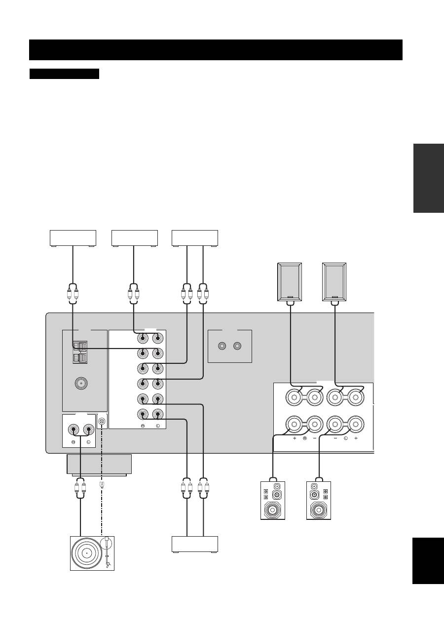
• Do not connect this unit or other components to the main power until all connections between components are complete.
• Do not let the bare speaker wires touch each other or do not let them touch any metal part of this unit. This could damage this unit and/
or the speakers.
• All connections must be correct: L (left) to L, R (right) to R, “+” to “+” and “–” to “–”. If the connections are faulty, no sound will be
heard from the speakers, and if the polarity of the speaker connections is incorrect, the sound will be unnatural and lack bass. Also,
refer to the owner’s manual for each of your components.
• Use the RCA type pin plug cables for audio components except speakers.
y
• The PHONO jacks are designed to connect a turntable with an MM or high-output MC cartridge. If you have a turntable with a low-
output MC cartridge, use an in-line boosting transformer or an MC-head amplifier when connecting your turntable to the PHONO
jacks.
• Connect your turntable to the GND terminal to reduce noise in the signal. However, you may hear less noise without the connection to
the GND terminal for some record players.
CONNECTIONS
CAUTION
GND
AM
ANT
FM
ANT
75
Ω
UNBAL.
CD/DVD
AUX
IN
(PLAY)
IN
(PLAY)
OUT
(REC)
OUT
(REC)
TAPE
MD
AUDIO
TUNER
AUDIO
GND
REMOTE
PHONO
IN
OUT
SPEAKERS
A
B
R
L
L
R
L
R
L
R
L
R
L
R
L
R
+
–
–
+
+
–
–
+
Turntable
CD/DVD player,
etc.
Au
dio
in
MD recorder,
etc.
Tape deck, etc.
Au
di
o ou
t
Au
di
o ou
t
GN
D
Au
di
o ou
t
Au
dio
in
Au
di
o ou
t
MP3 player, etc.
Au
di
o ou
t
Speakers B
Speakers A
10
CONNECTIONS
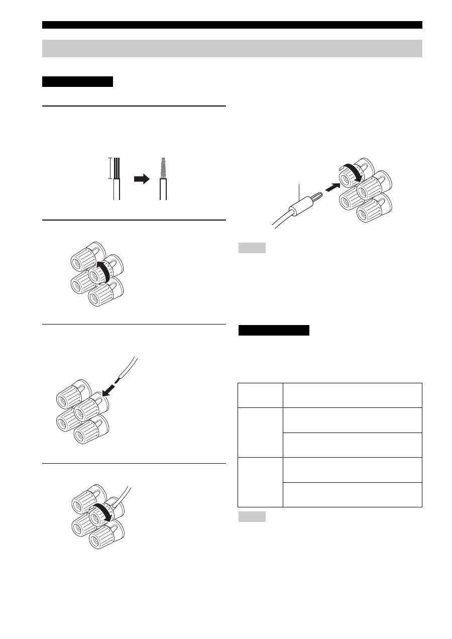
Be sure to connect the left channel (L), right channel (R), “+” (red) and “–” (black) properly.
Before connecting the speakers, make sure that the power of this unit is off.
1
Remove approximately 10 mm (3/8 in) of
insulation from the end of each speaker
cable and twist the exposed wires of the
cable together to prevent short circuits.
2
Unscrew the knob.
3
Insert one bare wire into the hole in the side
of each terminal.
4
Tighten the knob to secure the wire.
■
Connecting the banana plug
(U.S.A., Canada, Australia and General
models only)
First, tighten the knob and then insert the banana plug into
the end of the corresponding terminal.
• One or two speaker sets can be connected to this unit. If you use
only one speaker set, connect it to either the SPEAKERS A or B
terminals.
• Use speakers with the specified impedance shown on the rear
panel of this unit.
■
IMPEDANCE SELECTOR switch
Do not slide the IMPEDANCE SELECTOR switch while the
power of this unit is turned on, as doing so may damage the unit.
Select the switch position (left or right) according to the
impedance of the speakers in your system.
• The Canada model cannot use two separate speaker sets (A and
B) simultaneously when the IMPEDANCE SELECTOR switch
is slid to the right position.
• If this unit fails to turn on, the IMPEDANCE SELECTOR
switch may not be fully slid to either position. If this is the case,
slide the switch all the way to either position when the power
supply to this unit is completely cut off.
Connecting speakers
CAUTION
10 mm (3/8 in)
Red: positive (+)
Black: negative (–)
Red: positive (+)
Black: negative (–)
Red: positive (+)
Black: negative (–)
Notes
Switch
position
Impedance level
Right
If you use one set (A or B), the impedance of
each speaker must be 8
Ω
or higher.
If you use two sets (A and B), the impedance
of each speaker must be 16
Ω
or higher.
Left
If you use one set (A or B), the impedance of
each speaker must be 4
Ω
or higher.
If you use two sets (A and B), the impedance
of each speaker must be 8
Ω
or higher.
Notes
Banana plug
CAUTION
11
CONNECTIONS
PREP
ARA
TION
English
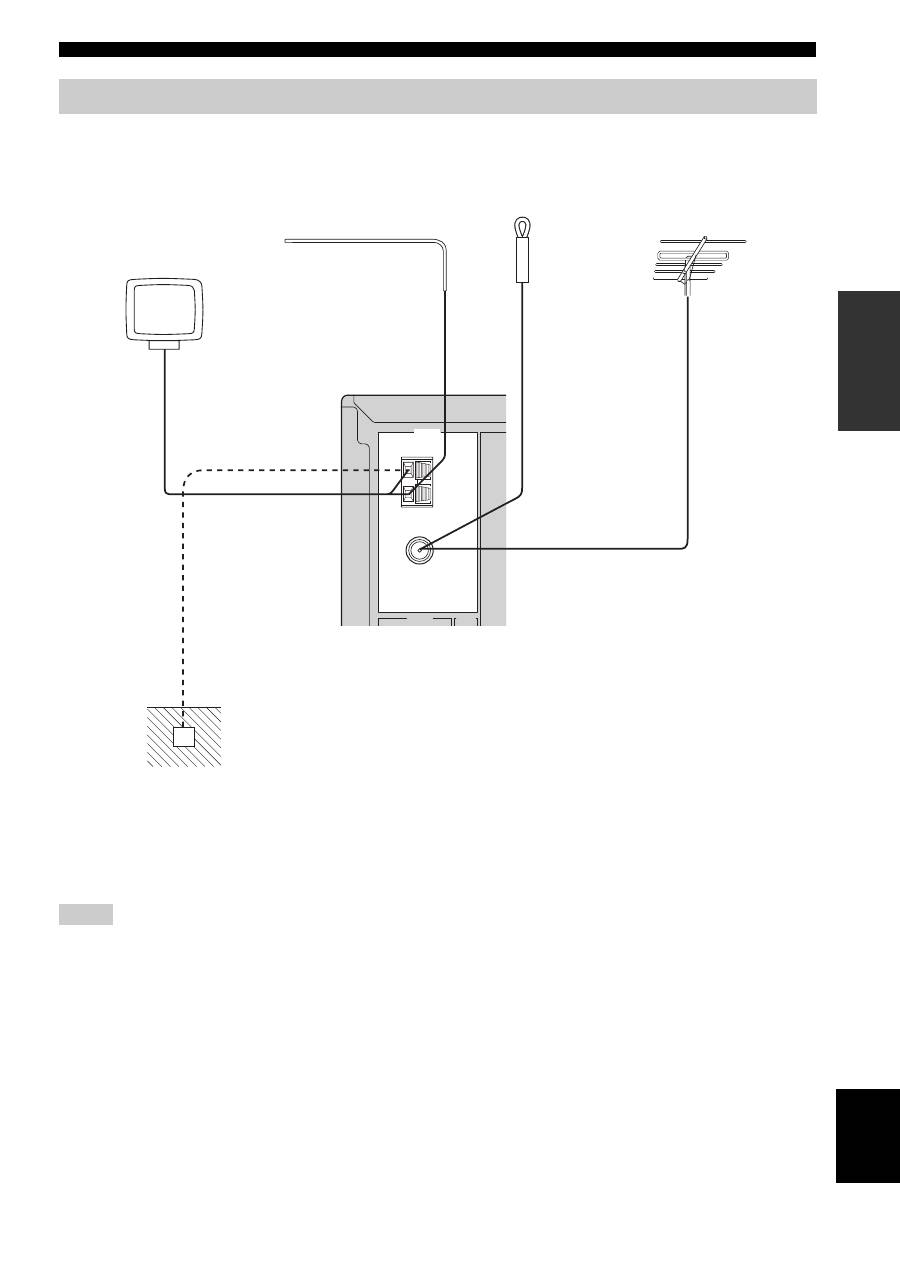
Both AM and FM indoor antennas are included with this unit. In general, these antennas should provide sufficient signal
strength. Connect each antenna correctly to the designated terminals.
• A properly installed outdoor antenna provides clearer reception than an indoor one. If you experience poor reception quality, an
outdoor antenna may improve the quality. Consult your nearest authorized YAMAHA dealer or service center about outdoor antennas.
• If you connect an outdoor FM antenna to this unit, do not connect the indoor FM antenna to this unit.
• To minimize interference from automobile ignition, locate the antenna as far from heavy traffic as possible.
• Keep the feeder cable or coaxial cable as short as possible. Do not bundle or roll up excess cable.
• The antenna should be placed at least 2 meters from reinforced concrete walls or metal structures.
Connecting the AM and FM antennas
Notes
GND
AM
ANT
FM
ANT
75
Ω
UNBAL.
TUNER
AUDIO
GND
AM loop antenna
(included)
Indoor FM antenna
(included)
Outdoor AM antenna
Use a 5 to 10 m of vinyl-
covered wire extended
outdoors from a window.
Outdoor FM antenna
Ground (GND terminal)
For maximum safety and
minimum interference, connect
the antenna GND terminal to a
good earth ground. A good earth
ground is a metal stake driven into
moist earth.
12
CONNECTIONS
■
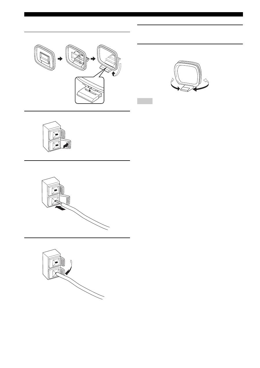
Connecting the AM loop antenna
1
Set up the AM loop antenna.
2
Press and hold the tab.
3
Insert the AM loop antenna lead wires into
the AM ANT terminal.
4
Release the tab.
5
Repeat steps 2 to 4 to insert the AM loop
antenna lead wires into the GND terminal.
6
Orient the AM loop antenna for the best
reception.
• The AM loop antenna should be placed away from this unit.
• A properly installed outdoor antenna provides clearer reception
than an indoor one. If you experience poor reception quality, an
outdoor antenna may improve the quality. It is recommended
that you should connect a 5 to 10 m of vinyl-covered wire to the
AM ANT terminal and extend it outdoors from a window.
Consult your nearest authorized YAMAHA dealer or service
center about outdoor antennas.
• The AM loop antenna should always be connected, even if an
outdoor AM antenna is connected to this unit.
Notes
13
CONNECTIONS
PREP
ARA
TION
English
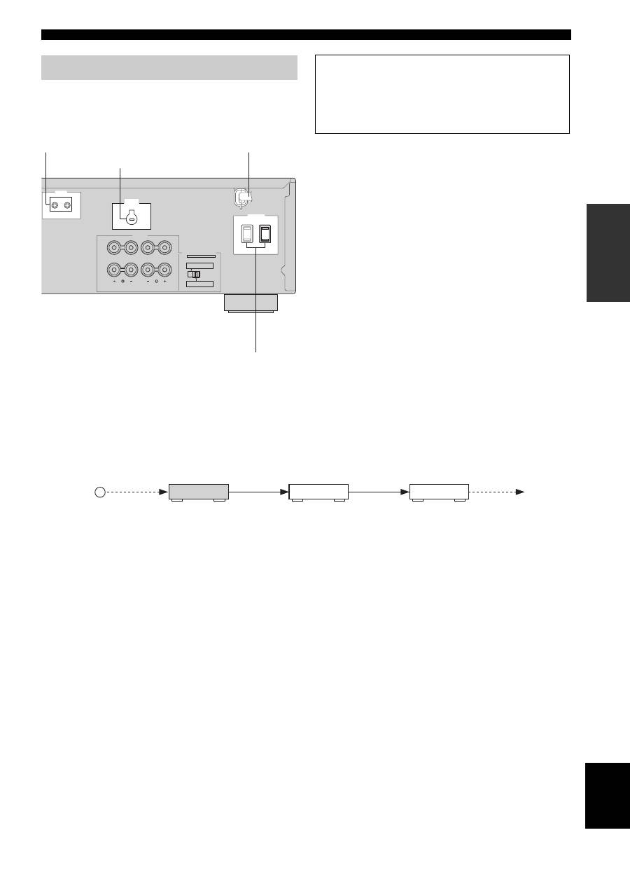
Plug the power supply cord into the AC wall outlet after
all other connections are complete.
■
REMOTE jacks
Some YAMAHA models are able to connect directly to the
REMOTE jack on the rear panel of this unit. If you own these
products, you may not need to use an infrared emitter. Up to six
YAMAHA components can be connected as shown below.
■
AC OUTLET(S) (SWITCHED)
Australia model ......................................................1 outlet
Other models ....................................................... 2 outlets
Use these outlets to connect the power supply cords from
your other components to this unit. The AC OUTLET(S)
supplies power to any connected components whenever
the power of this unit is turned on. For information on the
maximum power (total power consumption of
components), see “SPECIFICATIONS” on page 33.
■
VOLTAGE SELECTOR
(Asia and General models only)
VOLTAGE SELECTOR on the rear panel of this unit must
be set for your local main voltage BEFORE plugging the
power supply cord into the AC wall outlet.
Voltages are as follows:
Asia model ......................... AC 220/230–240 V, 50/60 Hz
General model ...... AC 110/120/220/230–240 V, 50/60 Hz
Connecting the power supply cord
REMOTE
IN
OUT
A OR B: 4
Ω
MIN. /SPEAKER
A + B: 8
Ω
MIN. /SPEAKER
A OR B: 8
Ω
MIN. /SPEAKER
A + B:16
Ω
MIN. /SPEAKER
IMPEDANCE SELECTOR
SET BEFORE POWER ON
SPEAKERS
CLASS 2 WIRING
VOLTAGE
SELECTOR
A
B
AC OUTLETS
SWITCHED
(General model)
AC power supply cord
VOLTAGE SELECTOR
AC OUTLET(S)
REMOTE jacks
Memory back-up
The memory back-up circuit prevents the stored data
from being lost. However, the stored data will be lost if
the power cord is disconnected from the AC wall outlet
for more than one week.
OUT
OUT
IN
REMOTE
IN
REMOTE
OUT
IN
REMOTE
REMOTE
This unit
YAMAHA
component
YAMAHA
component
Infrared signal
receiver
14
CONNECTIONS
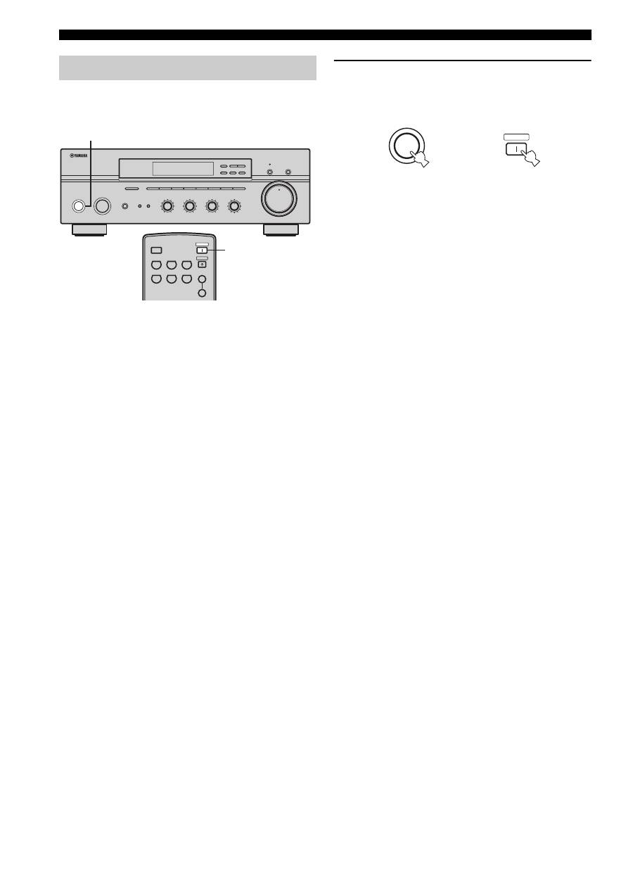
When all connections are complete, turn on the power of
this unit.
1
Press STANDBY/ON on the front panel (or
POWER on the remote control) to turn on this
unit.
Press STANDBY/ON on the front panel (or
STANDBY on the remote control) to set this unit to
the standby mode.
Turning on and off this unit
STANDBY
/ON
INPUT
PHONES
BASS
TAPE MONITOR
PURE DIRECT
5
5
1
0
1
4
4
2
2
3
3
+
–
VOLUME
l
TUNING
h
FM/AM
EDIT
A/B/C/D/E
1
2
3
4
5
6
7
8
MEMORY
MAN'L/AUTO FM
TUNING MODE
AUTO/MAN'L
TREBLE
5
5
1
0
1
4
4
2
2
3
3
+
–
BALANCE
5
5
1
0
1
4
4
2
2
3
3
R
L
LOUDNESS
5
7
1
FLAT
6
4
8
2
10
–30dB
3
9
SPEAKERS
B
A
1
0
12
12
2
8
4
∞
20
20
60
60
26
26
40
40
16
16
-dB
-dB
CD/DVD
PHONO
TUNER
MD
TAPE
AUX
SPEAKERS
B
A
POWER
STANDBY
SLEEP
1
STANDBY
/ON
Front panel
Remote control
or
POWER
Оглавление
- CAUTION: READ THIS BEFORE OPERATING YOUR UNIT.
- CONTENTS
- FEATURES SUPPLIED ACCESSORIES
- CONTROLS AND FUNCTIONS
- CONNECTIONS
- PLAYING AND RECORDING
- FM/AM TUNING
- RADIO DATA SYSTEM (EUROPE MODEL ONLY)
- ADVANCED SETUP
- TROUBLESHOOTING
- SPECIFICATIONS
- ATTENTION: VEUILLEZ LIRE CE QUI SUIT AVANT D’UTILISER L’APPAREIL.
- TABLE DES MATIÉRES
- PARTICULARITÉS ACCESSOIRES FOURNIS
- COMMANDES ET FONCTIONS
- RACCORDEMENTS
- LECTURE ET ENREGISTREMENT
- SYNTONISATION FM/AM
- RADIO DATA SYSTEM (MODÈLE POUR L’EUROPE SEULEMENT)
- RÉGLAGES APPROFONDIS
- GUIDE DE DÉPANNAGE
- CARACTÉRISTIQUES TECHNIQUES
- VORSICHT: VOR DER BEDIENUNG DIESES GERÄTES DURCHLESEN.
- INHALTSVERZEICHNIS
- MERKMALE MITGELIEFERTES ZUBEHÖR
- BEDIENUNGSELEMENTE UND IHRE FUNKTIONEN
- ANSCHLÜSSE
- WIEDERGABE UND AUFNAHME
- UKW-/MW-ABSTIMMUNG
- RADIO DATA SYSTEM (NUR MODELL FÜR EUROPA)
- WEITERFÜHRENDES SETUP
- STÖRUNGSBESEITIGUNG
- TECHNISCHE DATEN
- OBSERVERA: LÄS DETTA INNAN ENHETEN TAS I BRUK.
- INNEHÅLL
- EGENSKAPER MEDFÖLJANDE TILLBEHÖR
- BESKRIVNING AV REGLAGE M.M.
- ANSLUTNINGAR
- LJUDÅTERGIVNING OCH INSPELNING
- FM/AM-MOTTAGNING
- RADIO DATA SYSTEM (ENDAST MODELLER FÖR EUROPA)
- AVANCERAD INSTÄLLNING
- FELSÖKNING
- TEKNISKA DATA
- LET OP: LEES HET VOLGENDE VOOR U DIT TOESTEL IN GEBRUIK NEEMT.
- INHOUD
- KENMERKEN MEEGELEVERDE ACCESSOIRES
- BEDIENINGSORGANEN EN FUNCTIES
- AANSLUITINGEN
- WEERGAVE EN OPNAME
- AFSTEMMEN OP FM/AM RADIO
- RADIO DATA SYSTEEM (ALLEEN MODELLEN VOOR EUROPA)
- GEAVANCEERDE SETUP
- OPLOSSEN VAN PROBLEMEN
- TECHNISCHE GEGEVENS
- ПРЕДУПРЕЖДЕНИЕ: ВНИМАТЕЛЬНО ИЗУЧИТЕ ЭТО ПЕРЕД ИСПОЛЬЗОВАНИЕМ АППАРАТА.
- СОДЕРЖАНИЕ
- ОПИСАНИЕ ПОСТАВЛЯЕМЫЕ АКСЕССУАРЫ
- СИСТЕМЫ УПРАВЛЕНИЯ И ФУНКЦИИ
- СОЕДИНЕНИЯ
- ВОСПРОИЗВЕДЕНИЕ И ЗАПИСЬ
- НАСТРОЙКА ДИАПАЗОНА ЧМ/AM
- СИСТЕМА РАДИОДАННЫХ RADIO DATA SYSTEM (ТОЛЬКО МОДЕЛЬ ДЛЯ ЕВРОПЫ)
- ДОПОЛНИТЕЛЬНЫЕ НАСТРОЙКИ
- ВОЗМОЖНЫЕ НЕИСПРАВНОСТИ И СПОСОБЫ ИХ УСТРАНЕНИЯ
- ТЕХНИЧЕСКИЕ ХАРАКТЕРИСТИКИ
