Indesit KN 1E1 (W): Installation
Installation: Indesit KN 1E1 (W)
Installation
! Before operating your new appliance please read
The legs* provided with the
GB
this instruction booklet carefully. It contains important
appliance fit into the slots on the
information concerning the safe installation and
underside of the base of the
operation of the appliance.
cooker.
! Please keep these operating instructions for future
reference. Make sure that the instructions are kept with
the appliance if it is sold, given away or moved.
! The appliance must be installed by a qualified
Electrical connection
professional according to the instructions provided.
Fitting the power supply cable
! Any necessary adjustment or maintenance must be
performed after the appliance has been disconnected
The cable should be suited to the type of electrical
from the electricity supply.
connection used, according to the following
connection diagram:
Positioning and levelling
400V 3N~
1 2
3
4
5
! It is possible to install the appliance alongside
H05RR-F 5x2.5 CEI-UNEL 35363
H05VV-F 5x2.5 CEI-UNEL 35746
R
S
T
N
cupboards whose height does not exceed that of the
hob surface.
400V 2N~
12345
H05RR-F 4x4 CEI-UNEL 35363
H05VV-F 4x4 CEI-UNEL 35746
R
S
N
! Make sure that the wall in contact with the back of
the appliance is made from a non-flammable, heat-
230V 1N~
1
2
3
4
5
H05RR-F 3x4 CEI-UNEL 35363
resistant material (T 90°C).
H05VV-F 3x4 CEI-UNEL 35746
R
N
To install the appliance correctly:
To install the power
• Place it in the kitchen, dining room or the bed-sit
supply cable correctly:
(not in the bathroom).
1. Loosen the screw V
• If the top of the hob is higher than the cupboards,
in the terminal board
the appliance must be installed at least 200 mm
V
and pull the cover to
away from them.
open it (
see figure
).
• If the cooker is
installed underneath a wall
HOOD
cabinet, there must be a
Min. mm.
600
minimum distance of 420
mm.
mm between this cabinet
420
420
mm. with hood
mm. without hood
and the top of the hob.
650
700
Min.
Min. mm.
This distance should be
min.
min.
increased to 700 mm if
3
2
2. Position the
the wall cabinets are
1
connection support A
flammable (
see figure
).
(
see figure
) according
• Do not position blinds behind the cooker or less
to the connection
than 200 mm away from its sides.
diagram shown above.
B
• Any hoods must be installed according to the
The terminal board is
A
instructions listed in the relevant operating manual.
designed for single-
N
phase 230 V
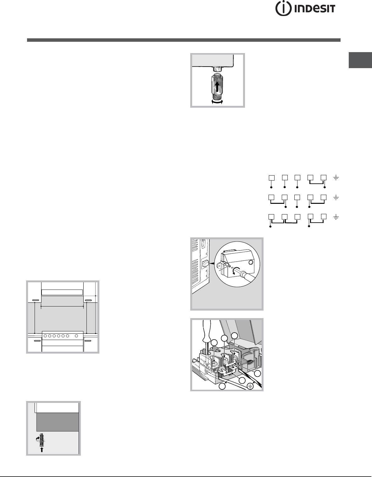
Levelling
connection: terminals 1, 2 and 3 are connected to
If it is necessary to level the
each other; jumper 4-5 is located in the lower area of
appliance, screw the adjustable
the terminal board.
feet* into the places provided on
3. Position wires N and
6 according to the diagram
66
66
each corner of the base of the
(
see figure
) and perform the connection by
cooker (
see figure
).
tightening the terminal board screws as much as
possible.
4. Position the remaining wires on terminals 1-2-3 and
tighten the screws.
13
5. Fix the power supply cable in place by fastening
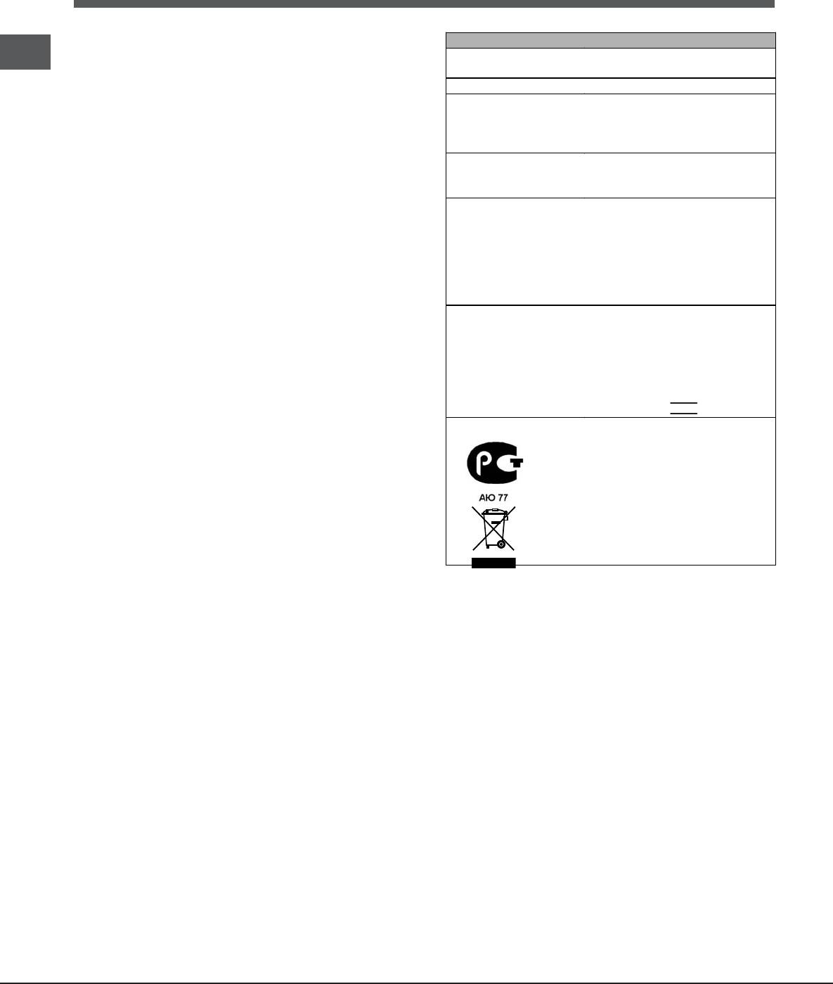
TECHNICAL DATA
GB
the cable clamp screw.
Oven dimensions
38x34x39 cm
6. Close the terminal board cover by tightening the
(WxDxH)
screws V.
Volume
50 l
Useful
width 42 cm
measurements
Connecting the supply cable to the mains
depth 44 cm
relating to the oven
height 18 cm
compartment
Install a standardised plug corresponding to the
Power supply
load indicated on the data plate located on the
voltage and
see data plate
appliance.
frequency
The appliance must be directly connected to the
Electric hob
mains using an omnipolar circuit-breaker with a
Front left
600 W
minimum contact opening of 3 mm installed between
Back left
2000 W
Back right
1500 W
the appliance and the mains. The circuit-breaker
Front right
1500 W
must be suitable for the charge indicated and must
Maximum absorption
comply with current electrical regulations (the
of the electric hob
5600 W
earthing wire must not be interrupted by the circuit-
Directive 2002/40/EC on the
breaker). The supply cable must be positioned so
label of electric ovens. Standard
that it does not come into contact with temperatures
EN 50304
higher than 50°C at any point.
ENERGY LABEL
Declared energy consumption
Before connecting the appliance to the power
for Natural convection Class –
supply, make sure that:
heating mode:
Static
• The appliance is earthed and the plug is compliant
EC Directives: 2006/95/EC
with the law.
dated 12/12/06 (Low Voltage)
• The socket can withstand the maximum power of
and subsequent amendments -
2004/108/EC dated 15/12/04
the appliance, which is indicated by the data
(Electromagnetic Compatibility)
plate.
and subsequent amendments -
• The voltage is in the range between the values
93/68/EEC dated 22/07/93 and
indicated on the data plate.
subsequent amendments -
• The socket is compatible with the plug of the
2002/96/EC.
appliance. If the socket is incompatible with the
1275/2008 (Stand-by/ Off mode)
plug, ask an authorised technician to replace it.
Do not use extension cords or multiple sockets.
! Once the appliance has been installed, the power
supply cable and the electrical socket must be
easily accessible.
! The cable must not be bent or compressed.
! The cable must be checked regularly and replaced
by authorised technicians only.
! The manufacturer declines any liability should
these safety measures not be observed.
We recommend cleaning the oven before using it for
the first time, following the instructions provided in
the "Care and maintenance" section.
Only available in certain models.
*
14
Оглавление
- Руководство по эксплуатации
- Установка
- Описание изделия
- Включение и эксплуатация
- Электрическая варочная панель
- Предосторожности и рекомендации
- Техническое обслуживание и уход
- Operating Instructions
- Installation
- Description of the appliance
- Start-up and use
- Using the electric hob
- Precautions and tips
- Care and maintenance
- Інструкціі з експлуатаціі
- Встановлення
- Опис приладу
- Включення і використання
- Електричні конфорки
- Запобіжні засоби и поради
- Догляд i технічне обслуговування
- Instrucţiuni de folosire
- Instalare
- Descriere aparatului
- Pornire şi utilizare
- Folosirea plitei eletrice
- Precauţii şi sfaturi
- Întreţinere şi curăţire


")
")

