Indesit K6G21S/R: Installation
Installation: Indesit K6G21S/R
Installation
The following instructions should be read by a qualified technician
subject to heat produced by external sources (ovens, fire-
to ensure that the appliance is installed, regulated and technically
places, stoves, etc. ) which are able to increase the tempera-
serviced correctly in compliance with current regulations.
ture of the cylinder above 50°C.
Important: remember to unplug the appliance from the mains
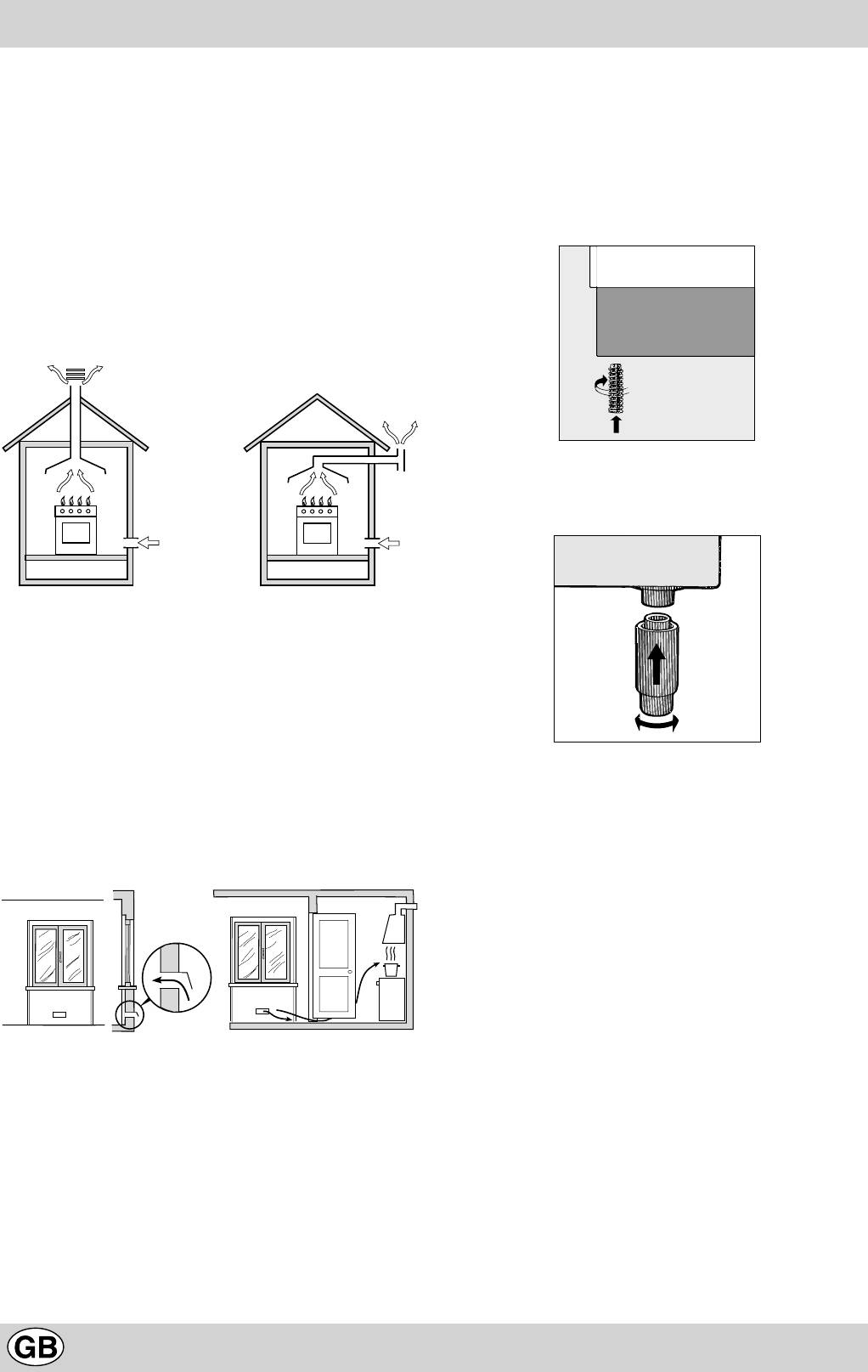
Levelling Your Appliance (only on certain models)
before regulating the appliance or carrying out any
4 support feet which are adjusted using screws are located
maintenance work.
in the lower part of the cooker. These level off the oven
Positioning
when necessary. It is essential that the cooker be standing
Important: This unit may be installed and used only in perma-
level.
nently ventilated rooms in accordance with current National Regu-
lations. The following requirements must be observed:
a) The room must be equipped with an exhaust system that
vents the combustion fumes to the outside. It may consist of
a hood or an electric fan that automatically starts each time
the appliance is turned on.
Mounting the legs (only on certain models)
Press-fit legs are supplied which fit under the base of your
cooker.
A Flue or Branched Flue System Directly to the outside
(only for cooking appliances)
b)
The room must also have a system to permit proper air circulation, needed
for combustion to occur normally. The flow of air needed for combustion
3
must not be less than 2 m
/h per kW of installed power. The air circulation
system may take air directly from the outside by means of a pipe with an
2
inner cross section of at least 100 cm
; the opening must not be able to be
accidentally blocked. For those appliances not equipped with a safety
device for accidental flame loss, the ventilation apertures must be in-
2
creased by 100%, with the minimum being 200cm
(Fig. A). The system
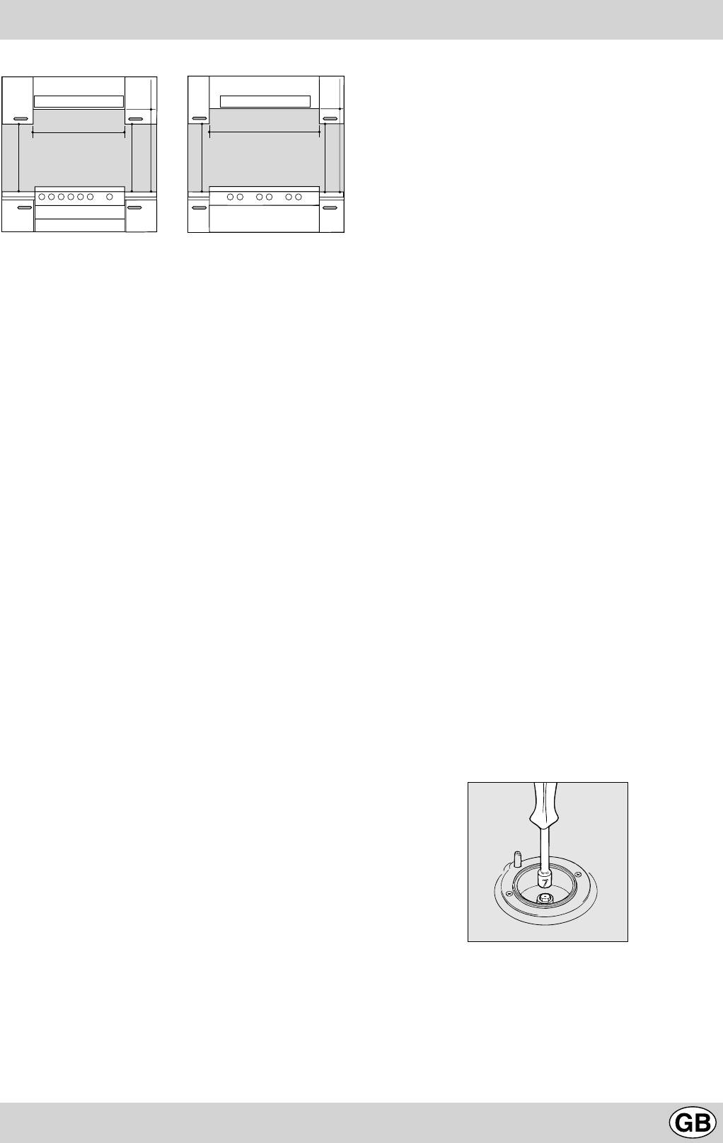
Installation of the cooker
can also provide the air needed for combustion by indirect means, i.e. from
The appliance can be installed next to cabinets, provided the
adjacent rooms fitted with air circulation tubes as described above. How-
height does not exceed that of the hob. If the cooker is placed
ever, these rooms must not be common rooms or bedrooms. (Fig. B).
touching walls or sides of neighbouring cabinets, these must be
Detail A Adjacent Room to be
Room Ventilated
capable of withstanding a temperature rise of 50°C above room
temperature. For a correct installation of the cooker the following
precautions must be followed:
a) The cooker may be located in a kitchen, a kitonen/diner or
bed sitting room, but not in a bathroom or shower room.
b) The furniture units next to the cooker, that is higher than the
working boards, must be placed at least 600 mm from the
A
edge of the board. Curtains must not be fitted immediately
behind the cooker or within 110 mm. of the sides of the cooker.
c) The hoods must be installed according to the requirements
Examples of Ventilation Increased Opening Between
Openings Comburent Air Door and Floor
in the hood handbook.
Fig. A Fig. B
d) Wall cabinets may be fitted in line with the sides of the base
c) Intensive and prolonged use of the appliance may result in
units, providing that the lower edge of the wall cabinet is a
the need for supplemental air circulation, e.g. opening win-
minimum of 420 mm. above the worktop. The minimum
dows or increasing mechanical venting (if present).
distance combustible material kitchen units can be fitted
d) Liquified petroleum gas is heavier than the air and, therefore,
directly above the worktop is 700 mm
(Fig. C and D)
.
settles downwards. Thus, rooms containing LPG cylinders
must also be equipped with apertures to the outside for ven-
tilation of gas in the case of leaks. LPG cylinders must not,
therefore, be installed or stored in rooms or storage areas
that are below ground level (cellars, etc.) whether they are
partially or completely full. It is a good idea to keep only the
cylinder being used in the room, positioned so that it is not
14
Tight control
Important: when installation has been completed, check the
HOOD
HOOD
pipe fitting for leaks with a soapy solution. Never use a flame.
Once the connection has been made, ensure that the flexible
Min. mm.
600
Min. mm.
900
metal tube does not touch any moving parts and is not crushed.
mm.
mm.
420
420
420
mm. with hood
Connecting the supply cable to the mains
420
mm. without hood
700 mm. without hood
650
700
Min.
Min. mm.
min. 650 mm. with hood
Min.
Install a normalised plug corresponding to the load indicated on
Min. mm.
min.
min.
min.
the data plate. When connecting the cable directly to the mains,
install an omnipolar circuit-breaker with a minimum contact
opening of 3 mm between the appliance and the mains. The
omnipolar circuit breaker should be sized according to the load
Fig. C Fig. D
and should comply with current regulations (the earth wire should
e) The wall in contact with the back of the cooker must be of
not be interrupted by the circuit breaker).
flameproof material.
The supply cable should be positioned so that it does not reach
a temperature of more than 50°C with respect to the room tem-
Connecting the gas
perature, along its length. Before making the connection, check
The appliance should be connected to the mains or to a gas
that:
cylinder in compliance with current directives. Before making the
• the limiter valve and the home system can support the
connection, check that the cooker is regulated for the gas supply
appliance load (see data plate);
you are using. If not, follow the instructions indicated in the
• the mains is properly earthed in compliance with current
paragraph “Adapting to different types of gas”. On some models
directives and regulations;
the gas supply can be connected on the left or on the right, as
• there is easy access to the socket and omnipolar circuit
necessary; to change the connection, reverse the position of the
breaker, once the hob has been installed.
hose holder with that of the cap and replace replace the gasket
N.B: never use reducers, adaptors or shunts since they can
(supplied with the appliance). When using liquid gas from a cylinder,
cause heating or burning.
install a pressure regulator which complies with current directive.
Important: check that the supply pressure complies with the
Adapting the cooker to different types of gas
values indicated in table 1 “Characteristics of the burners and
In order to adapt the cooker to a different type of gas with respect
nozzles” since this will ensure safe operation, correct consumption
to the gas for which it was produced (indicated on the label
and ensure a longer life to your appliance.
attached to the lid), follow these steps:
a) replace the hose holder mounted on the appliance with that
Connection with hose
supplied in the bag of “cooker accessories”.
Make the connection using a gas hose complying with the the
Important: the hose holder for liquid gas is marked 8, the hose
characteristics provided in current directive. The internal diameter
holder for methane gas is marked 13. Always fit the sealing
of the pipe used is as follows:
gasket.
- 8mm for liquid gas;
b) Replacing the burner nozzles on the hob:
- 13mm for methane gas.
• remove the grids and slide the burners from their housings;
When installing the hose, remember to take the following
• unscrew the nozzles using a 7 mm socket spanner, and
precautions:
replace them with nozzles for the new type of gas (see table
• No part of the hose should touch parts whose temperature
1 “Burner and nozzle characteristics”).
exceeds 50°C;
• replace all the components by repeating the steps in reverse
• The length of the hose should be less than 1500 mm;
order.
• The hose should not be subject to twisting or pulling, and
should not have bends or kinks.
• The hose should not touch objects with sharp edges, any
moving parts, and it should not be crushed;
• The full length of the hose should be easy to inspect in order
to check its condition;
Check that the hose fits firmly into place at the two ends and fix
it with clamps complying to current directive.If any of the above
recommendations can not be adopted, flexible metal pipes should
be used.
Should the cooker be installed according to the conditions of
Class 2, subdivision 1, only a flexible metal pipe which is in
compliance with current safety standards should be used to make
c) Minimum regulation of the hob burners:
the connection to the gas mains.
•
turn the tap to minimum;
• remove the knob and adjust the regulation screw, which is
Connecting a flexible jointless stainless steel pipe to a
positioned in or next to the tap pin, until the flame is small but
threaded attachment
steady.
Remove the hose holder fitted on the appliance. The gas supply
N.B.: in the case of liquid gas, the regulation screw must be
pipe fitting is a threaded 1/2 gas cylindrical male attachment.
screwed in to the bottom.
Only pipes and gaskets complying with current directives. The
• check that the flame does not turn off when you turn the tap
full length of the pipe must not exceed 2000 mm.
15
quickly from high to low.
d) Regulating the primary air of the burners:
The primary air of the burners requires no regulation.
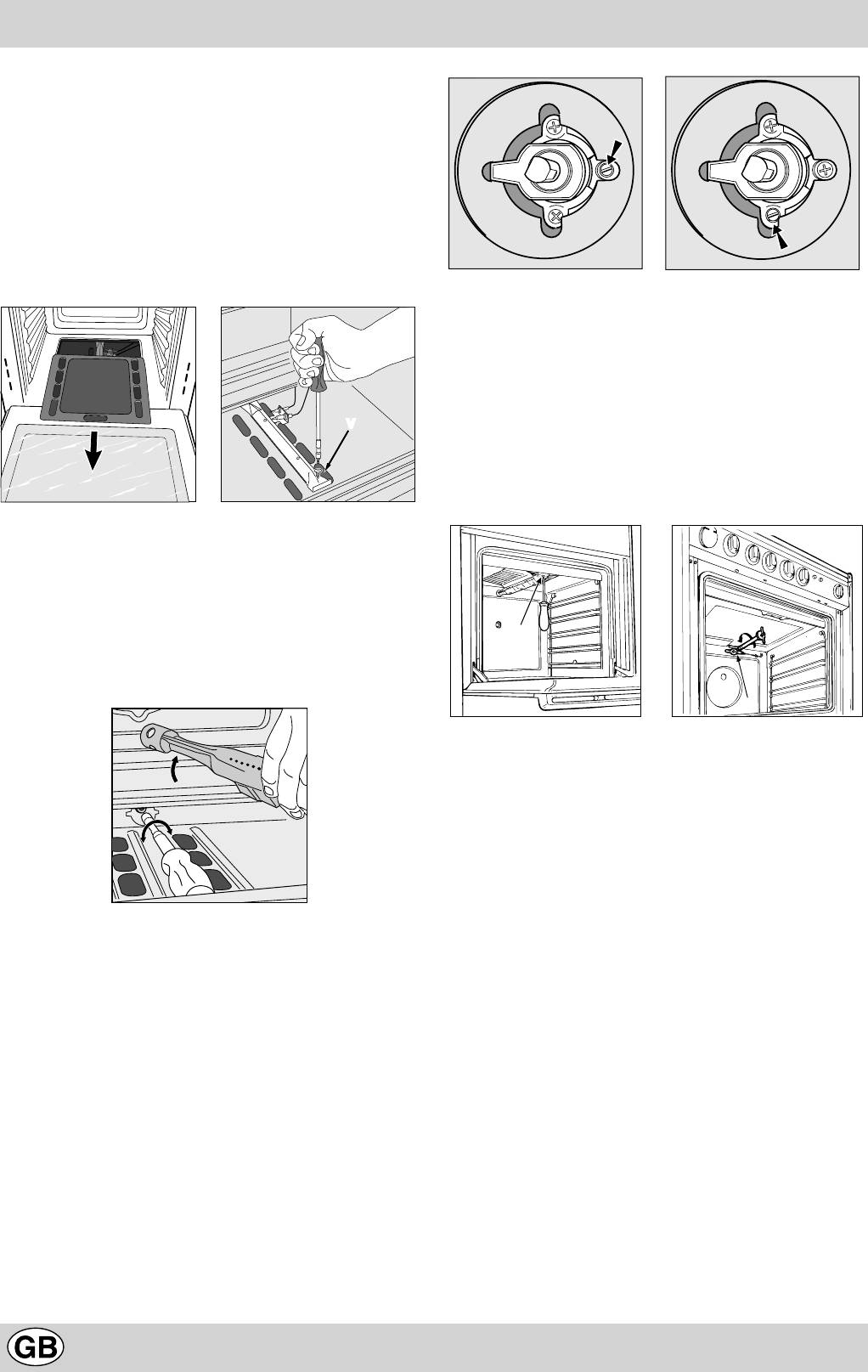
Adapting to different types of gas
In order to adapt the oven to a different type of gas with
respect to the gas for which it was manufactured (indi-
cated on the label), follow these simple steps:
a) Replacing the oven burner nozzle
· open the oven door fully
· pull out the sliding oven bottom
• check that the burner does not turn off when you turn the
· unscrew the burner fastening screws
knob from Max to Min and and when you open and close
the oven door quickly.
Adapting the gas grill to different types of gas
Replacing the nozzle of the grill burner:
• remove the screw and then slide out the grill burner “V”
(see Fig. E);
V
• unscrew the grill burner nozzle using the special socket
spanner for the nozzles (see Fig. F) or better still a 7 mm
socket spanner; replace the nozzle with a nozzle for the new
type of gas (see table 1).
· remove screw “V” and then the oven burner;
· Unscrew the oven burner nozzle using the special
socket spanner for the nozzles, or a 7 mm socket span-
ner, and replace it with a nozzle suited to the new type
of gas (see Table 1).
Take particular care handling the spark plug wires
and the thermocouple pipes.
· Replace all the parts, following the steps described
above in the reverse order.
b) Minimum regulation of the gas oven burner with thermostat:
• light the burner as described in the paragraph “the oven knob”
of the instruction booklet.
• turn the knob to Max for about 10 minutes and then turn the
knob to the Min setting;
• remove the knob;
• regulate the screw positioned outside the thermostat pin
until the flame is small but steady.
N.B.: in the case of liquid gas, the regulation screw must
be screwed in to the bottom.
16
V
I
Fig. E Fig. F
Regulating the Primary Air for the Oven Burner
The oven burner do not need to be regulated in terms of
primary air.
Important
On completion of the operation, replace the old rating sticker
with one indicating the new type of gas used. This sticker is
available from our Service Centres.
Note
Should the pressure of the gas used be different (or vary) from
the recommended pressure, it is necessary to fit a suitable
pressure regulator onto the inlet pipe in compliance with current
National Regulations relative to “regulators for channelled gas”.
Оглавление
- Avvertenze
- Istruzioni per l’installazione
- Caratteristiche dei bruciatori ed ugelli
- La cucina con forno gas e grill gas
- Le diverse funzioni presenti nella cucina
- I
- Consigli pratici per la cottura
- Consigli pratici per la cottura al forno
- Important safety warnings
- Installation
- Burner and nozzle characteristics
- The cooker with gas oven and gas grill
- The different functions and uses of the oven
- I
- Cooking advice
- Ïðåäóïðåæäåíèÿ
- Èíñòðóêöèè ïî ìîíòàæó
- Õàðàêòåðèñòèêè ãàçîâûõ ãîðåëîê è ôîðñóíîê
- Òåõíè÷åñêèå õàðàêòåðèñòèêè
- Ðàçíûå ôóíêöèè êóõîííîé ïëèòû
- I
- Ïðàêòè÷åñêèå ñîâåòû ïî ïðèãîòîâëåíèþ áëþä
- Ðåãóëÿðíîå òåõíè÷åñêîå îáñëóæèâàíèå è ÷èñòêà êóõîííîé ïëèòû
- Ïðàêòè÷åñêèå ñîâåòû ïî ïðèãîòîâëåíèþ áëþä â äóõîâîì øêàôó
- • jelez. A gázégõ begyújtásához
- I
- Instruc þ iuni pentru instalare
- Caracteristici ale arzãtoarelor ºi duzelor (injectoarelor)
- CARACTERISTICI TEHNICE
- Diverse funcþii ale aragazului
- I
- Sfaturi practice pentru procesul de coacere
- Sfaturi practice pentru coacerea la cuptor
- ÑÂÅÒÎÂÅÍ ÒÚÐÃÎÂÑÊÈ ÖÅÍÒÚÐ ÈÍÒÅÐÏÐÅÄ Áóë. Äðàãàí Öàíêîâ ¹ 36, îôèñ 412, ÑÎÔÈß 1057
- Ïðåïîðúêè
- Èíñòðóêöèè çà ìîíòàæ
- Õàðàêòåðèñòèêè íà ãîðåëêèòå è äþçèòå
- Òåõíè÷åñêè õàðàêòåðèñòèêè
- Ôóíêöèè íà ãîòâàðñêàòà ïå÷êà
- I
- Ïðàêòè÷åñêè ñúâåòè çà èçïîëçâàíå íà êîòëîíèòå
- Ïðàêòè÷åñêè ñúâåòè çà ãîòâåíå íà ôóðíà


