Dell Precision 380 – страница 2
Инструкция к Монитору Dell Precision 380
Оглавление
- Примечания, уведомления и предупреждения Сокращения и аббревиатуры
- Содержание
- Источники информации Что требуется найти? Информация находится здесь
- Что требуется найти? Информация находится здесь
- Что требуется найти? Информация находится здесь
- Что требуется найти? Информация находится здесь
- Установка компьютера (ориентация компьютера с корпусом Tower) 1 2
- 3
- Видеоплата для подключения одного и двух мониторов, с одним разъемом Адаптер для двух кабелей VGA: Адаптер для подключения двух кабелей DVI:
- Видеоплата для подключения двух мониторов с одним разъемом DVI и одним разъемом VGA Видеоплата с двумя разъемами DVI для подключения двух мониторов
- 4 5
- 6 Установка компьютера (ориентация настольного компьютера) 1
- 2 3
- Видеоплата для подключения одного и двух мониторов, с одним разъемом Адаптер для двух кабелей VGA: Адаптер для подключения двух кабелей DVI:
- Видеоплата для подключения двух мониторов с одним разъемом DVI и одним разъемом VGA Видеоплата с двумя разъемами DVI для подключения двух мониторов
- 4 5 6
- Информация о компьютере Вид спереди (ориентация компьютера с корпусом Tower) 5 индикатор обращения к жесткому диску
- 14 индикатор сетевого соединения
- Вид сзади (ориентация компьютера с корпусом Tower)
- Вид спереди (ориентация настольного компьютера)
- 12 индикатор сетевого соединения
- Вид сзади (ориентация настольного компьютера) Разъемы на задней панели
- 5 индикатр обращения к сети
- 12 разъем клавиатуры Подключайте стандартную клавиатуру к фиолетовому разъему клавиатуры. USB-клавиатуру следует подключать к разъему USB.
- Вид изнутри
- Цвет кабелей Компоненты системной платы
- Поиск руководства пользователя
- Снятие крышки корпуса компьютера
- Уход за компьютером
- Устранение неисправностей Советы по поиску и устранению неисправностей Разрешение вопросов несовместимости программного и аппаратного обеспечения Использование функции восстановления системы Microsoft Windows XP
- Создание точки восстановления Восстановление более раннего рабочего состояния компьютера Отмена последнего восстановления системы
- Включение восстановления системы Использование последней удачной конфигурации Другие возможности решения конфликтов программного обеспечения и оборудования Dell Diagnostics Когда использовать программу Dell Diagnostics
- Запуск программы Dell Diagnostics с жесткого диска Запуск программы Dell Diagnostics с компактдиска Drivers and Utilities (Драйверы и Утилиты)
- Перед началом тестирования Звуковые сигналы Код Причина
- Код Причина
- Сообщения об ошибках Индикаторы диагностики Индикаторы Описание проблемы Варианты решения
- Индикаторы Описание проблемы Варианты решения
- Индикаторы Описание проблемы Варианты решения
- Индикаторы Описание проблемы Варианты решения
- Индикаторы Описание проблемы Варианты решения
- Индикаторы Описание проблемы Варианты решения
- Часто задаваемые вопросы Как сделать... Решение Источник информации
- Как сделать... Решение Источник информации
- Указатель
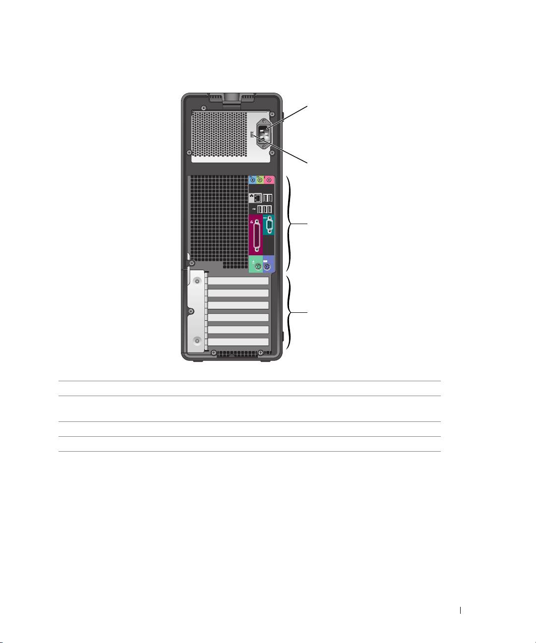
Back View (Tower Orientation)
1
2
3
4
1 power connector Insert the power cable into this connector.
2 voltage selection switch See the safety instructions in the Product Information Guide for more
information.
3 back-panel connectors Plug serial, USB, and other devices into the appropriate connector.
4 card slots Access connectors for any installed PCI or PCI Express cards.
Quick Reference Guide 21
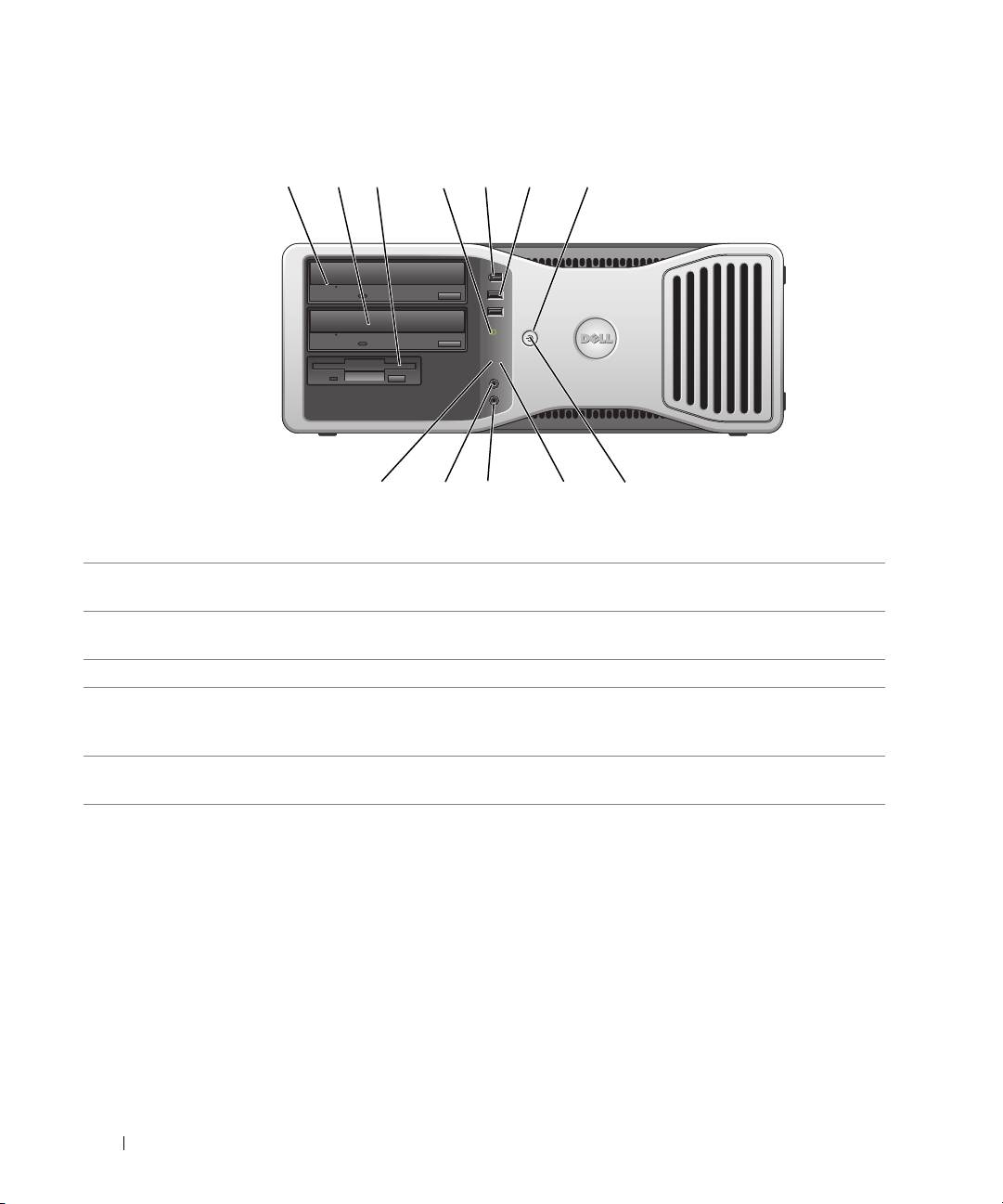
Front View (Desktop Orientation)
4
3
2
1
www.dell.com | support.dell.com
22 Quick Reference Guide
1 2 7
89101112
3
4
5 6
1 upper 5.25-inch drive
This bay holds a CD/DVD drive.
bay
2 lower 5.25-inch drive bay This bay holds an optional CD/DVD drive or an optional third hard drive (serial
ATA or SCSI).
3 3.5-inch drive bay You can use the bay for a floppy drive or an optional Media Card Reader.
4 hard-drive activity light The hard-drive activity light is on when the computer reads data from or writes
data to the hard drive. The light might also be on when a device such as your CD
player is operating.
5 IEEE 1394 connector
Use the optional IEEE 1394 connectors for high-speed data devices such as digital
(optional)
video cameras and external storage devices.

6 USB 2.0 connectors (2) Use the front USB connectors for devices that you connect occasionally, such as
flash memory keys or cameras, or for bootable USB devices (see
system setup
for
more information on booting to a USB device).
It is recommended that you use the back USB connectors for devices that typically
remain connected, such as printers and keyboards.
7 power button Press to turn on the computer.
NOTE: The power button can also be used to wake the computer or to place it into a
power-saving state. See "Power Management" for more information.
NOTICE: To avoid losing data, do not use the power button to turn off the
computer. Instead, perform an operating system shutdown.
8 power light The power light illuminates and blinks or remains solid to indicate different states:
• No light — The computer is turned off.
• Steady green — The computer is in a normal operating state.
• Blinking green — The computer is in a power-saving state.
• Blinking or solid amber — See "Power Problems."
To exit from a power-saving state, press the power button or use the keyboard or
the mouse if it is configured as a wake device in the Windows Device Manager. For
more information about sleep states and exiting from a power-saving state, see
"Power Management."
See "Diagnostic Lights" on page 37 for a description of light codes that can help
you troubleshoot problems with your computer.
9 diagnostic lights (4) Use the lights to help you troubleshoot a computer problem based on the
diagnostic code. For more information, see "Diagnostic Lights" on page 37.
10 microphone connector Use the microphone connector to attach a personal computer microphone for
voice or musical input into a sound or telephony program.
11 headphone connector Use the headphone connector to attach headphones.
12 network link light The network link light is on when a good connection exists between a 10-Mbps,
100-Mbps, or 1000-Mbps (or 1-Gbps) network and the computer.
Quick Reference Guide 23
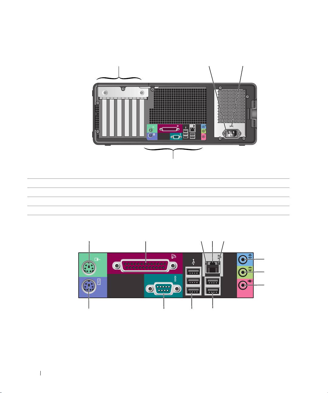
Back View (Desktop Orientation)
www.dell.com | support.dell.com
Back-Panel Connectors
24 Quick Reference Guide
32
4
1
1 card slots Access connectors for any installed PCI or PCI Express cards.
2 power connector Insert the power cable into this connector.
3 voltage selection switch See the safety instructions in the Product Information Guide for more information.
4 back-panel connectors Plug serial, USB, and other devices into the appropriate connector.
1
2 345
6
7
8
9101112

1 mouse connector Plug a standard mouse into the green mouse connector. Turn off the computer
and any attached devices before you connect a mouse to the computer. If you have
a USB mouse, plug it into a USB connector.
®
If your computer is running the Microsoft
Windows XP operating system, the
necessary mouse drivers have been installed on your hard drive.
2 parallel connector Connect a parallel device, such as a printer, to the parallel connector. If you have a
USB printer, plug it into a USB connector.
NOTE: The integrated parallel connector is automatically disabled if the computer
detects an installed card containing a parallel connector configured to the same
address. For more information, see "System Setup Options" in the User’s Guide.
3 link integrity light
• Green — A good connection exists between a 10-Mbps network and the
computer.
• Orange — A good connection exists between a 100-Mbps network and the
computer.
• Yellow — A good connection exists between a 1000-Mbps (or 1-Gbps) network
and the computer.
• Off — The computer is not detecting a physical connection to the network.
4 network adapter
To attach your computer to a network or broadband device, connect one end of a
connector
network cable to either a network jack or your network or broadband device.
Connect the other end of the network cable to the network adapter connector on
your computer. A click indicates that the network cable has been securely
attached.
NOTE: Do not plug a telephone cable into the network connector.
On computers with an additional network connector card, use the connectors on
the card and on the back of the computer when setting up multiple network
connections (such as a separate intra- and extranet).
It is recommended that you use Category 5 wiring and connectors for your
network. If you must use Category 3 wiring, force the network speed to 10 Mbps to
ensure reliable operation.
5 network activity light Flashes a yellow light when the computer is transmitting or receiving network
data. A high volume of network traffic may make this light appear to be in a steady
"on" state.
Quick Reference Guide 25

6 line-in connector Use the blue line-in connector to attach a record/playback device such as a cassette
player, CD player, or VCR.
On computers with a sound card, use the connector on the card.
7 line-out connector Use the green line-out connector to attach headphones and most speakers with
integrated amplifiers.
On computers with a sound card, use the connector on the card.
8 microphone connector Use the pink microphone connector to attach a personal computer microphone
for voice or musical input into a sound or telephony program.
On computers with a sound card, the microphone connector is on the card.
9 USB 2.0 connectors (2) Use the back USB connectors for devices that typically remain connected, such as
printers and keyboards.
www.dell.com | support.dell.com
It is recommended that you use the front USB connectors for devices that you
connect occasionally, such as flash memory keys or cameras, or for bootable USB
devices.
10 USB 2.0 connectors (3) Use the back USB connectors for devices that typically remain connected, such as
printers and keyboards.
It is recommended that you use the front USB connectors for devices that you
connect occasionally, such as flash memory keys or cameras, or for bootable USB
devices.
11 serial connector Connect a serial device, such as a handheld device, to the serial port. The default
designations are COM1 for serial connector 1 and COM2 for the optional serial
connector 2.
For more information, see "System Setup Options" in the User’s Guide
.
12 keyboard connector If you have a standard keyboard, plug it into the purple keyboard connector. If you
have a USB keyboard, plug it into a USB connector.
26 Quick Reference Guide
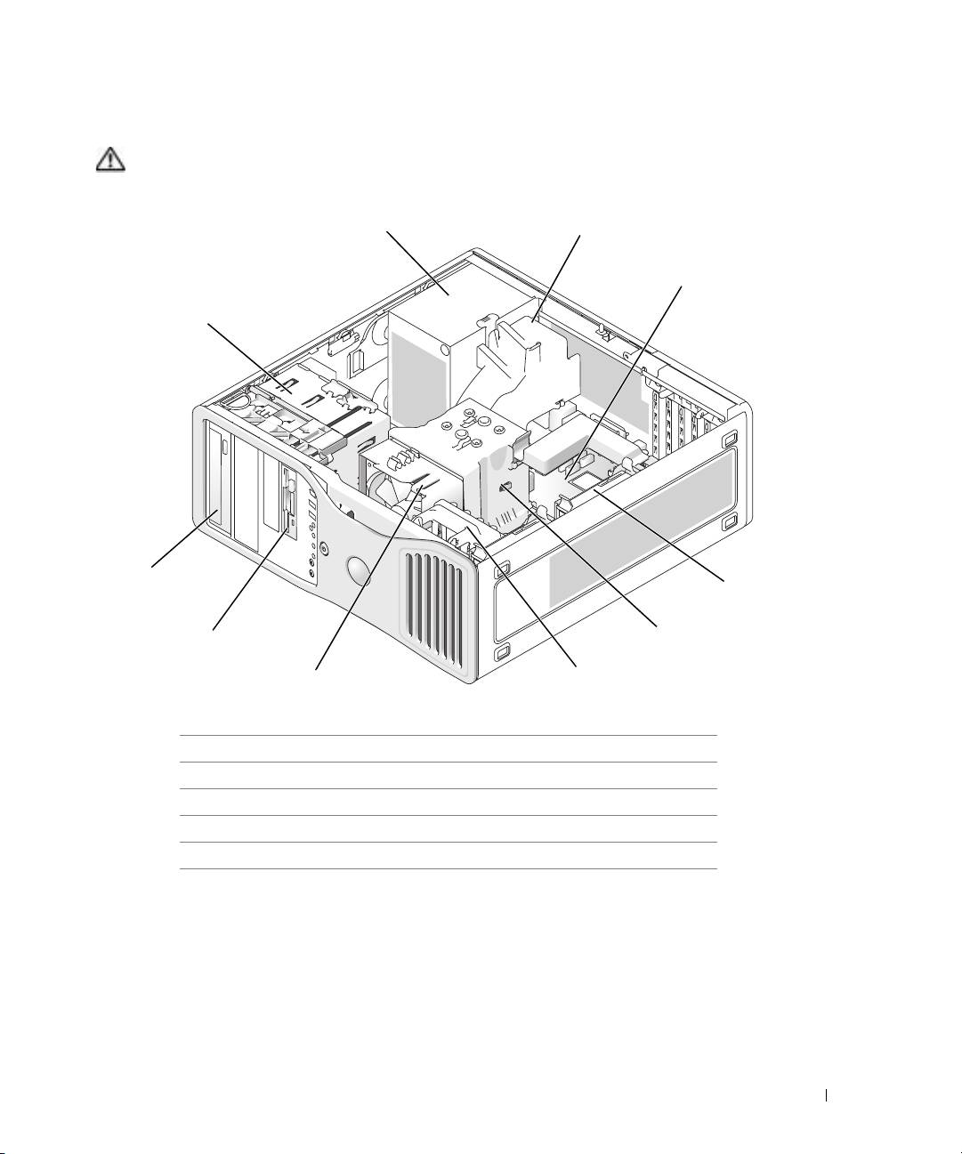
Inside View
CAUTION: Before you begin any of the procedures in this section, follow the safety instructions in the
Product Information Guide.
1 power supply 6 card fan
2 optional additional fan 7 processor fan
3 system board 8 lower 3.5-inch drive bay
4 hard drive 9 upper 5.25-inch drive bay
5 processor airflow shroud 10 drive cage
Quick Reference Guide 27
1
10
9
4
8
7
2
3
5
6
Cable Colors
Device Color
Hard drive blue cable
Floppy drive black pull tab
CD/DVD drive orange pull tab
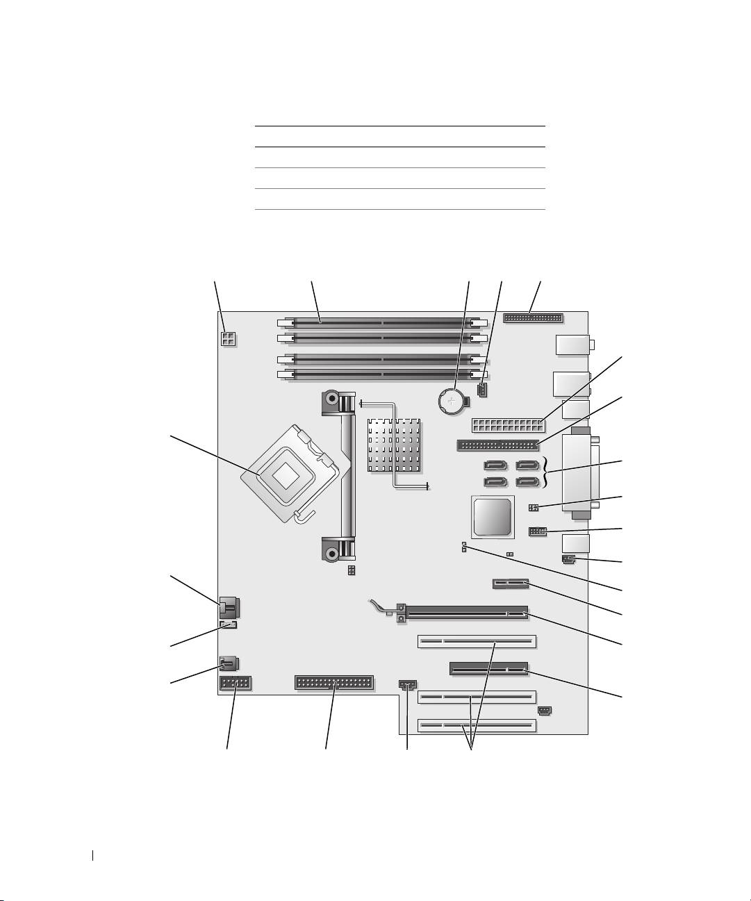
System Board Components
www.dell.com | support.dell.com
6
8
28 Quick Reference Guide
1
9
2
23
3 4 5
7
10
11
22
12
13
21
14
20
15
19
18
1617

1 power connector (12VPOWER) 13 PCI-Express x1 card slot
2 memory module connectors 14 PCI-Express x16 up to 150w card slot
3 battery socket (BATTERY) 15 PCI-Express x8 card slot (wired as x4)
4 memory fan connector (FAN_MEM) 16 PCI card slots (1-3)
5 front panel connector 17 external light connector (AUX LED)
6 main power connector (POWER) 18 floppy drive (FLOPPY)
7 IDE drive connector (IDE) 19 serial connector (SERIAL2)
8 SATA connectors (SATA-1, SATA-3, SATA-0,
20 card cage fan (FAN CARD CAGE)
SATA-2)
9 RTC reset jumper (RTCRST) 21 internal speaker connector (INT_SPKR)
10 Flexbay connector (FLEXBAY) 22 processor fan connector (FAN_CPU)
11 chassis intrusion header 23 processor connector (CPU)
12 password jumper (PASS)
Locating Your User’s Guide
Your
User’s Guide
contains additional information about your computer such as:
• Technical specifications
• Information for changing the orientation of your computer from a desktop to a tower
• Front and back views of your computer, including all of the available connectors
• Inside views of your computer, including a detailed graphic of the system board and the
connectors
• Instructions for cleaning your computer
• Information on software features, such as LegacySelect Technology control, using a password,
and system setup options
• Tips and information for using the Microsoft Windows XP operating system
• Instructions for removing and installing parts, including memory, cards, drives, the
microprocessor, and the battery
• Information for troubleshooting various computer problems
• Instructions for using the Dell Diagnostics and reinstalling drivers
• Information on how to contact Dell
You can access the
User’s Guide
from your hard drive or the Dell Support website at
support.dell.com
.
Quick Reference Guide 29

To access the User’s Guide from your hard drive:
Click the
Start
button and click
Help and Support
.
To access your User’s Guide from the Dell Support website:
1
Go to
support.dell.com
.
2
Follow the prompts on the website that ask you for information specific to your computer.
3
At the Dell Support website home page, click
Reference
, click
User’s Guides
, click
Systems
,
and then select your computer.
Removing the Computer Cover
www.dell.com | support.dell.com
CAUTION: Before you begin any of the procedures in this section, follow the safety instructions in the
Product Information Guide.
CAUTION: To guard against electrical shock, always unplug your computer from the electrical outlet
before removing the cover.
NOTICE: Before touching anything inside your computer, ground yourself by touching an unpainted
metal surface, such as the metal at the back of the computer. While you work, periodically touch an
unpainted metal surface to dissipate any static electricity that could harm internal components.
NOTICE: To avoid losing data, save and close any open files and exit any open programs before you turn
off your computer.
1
Shut down the operating system:
a
Save and close any open files, exit any open programs, click the
Start
button, and then
click
Turn Off Computer
.
b
In the
Turn off computer
window, click
Turn off
.
The computer turns off after the operating system shutdown process finishes.
2
Ensure that the computer and any attached devices are turned off. If your computer and
attached devices did not automatically turn off when you shut down your operating system,
turn them off now.
3
If you have installed a security cable, remove it from the security cable slot.
NOTICE: Ensure that you are working on a level, protected surface to avoid scratching either the
computer or the surface on which it is resting.
4
Lay your computer on a flat surface with the computer cover facing up.
5
Pull back the cover latch release.
30 Quick Reference Guide
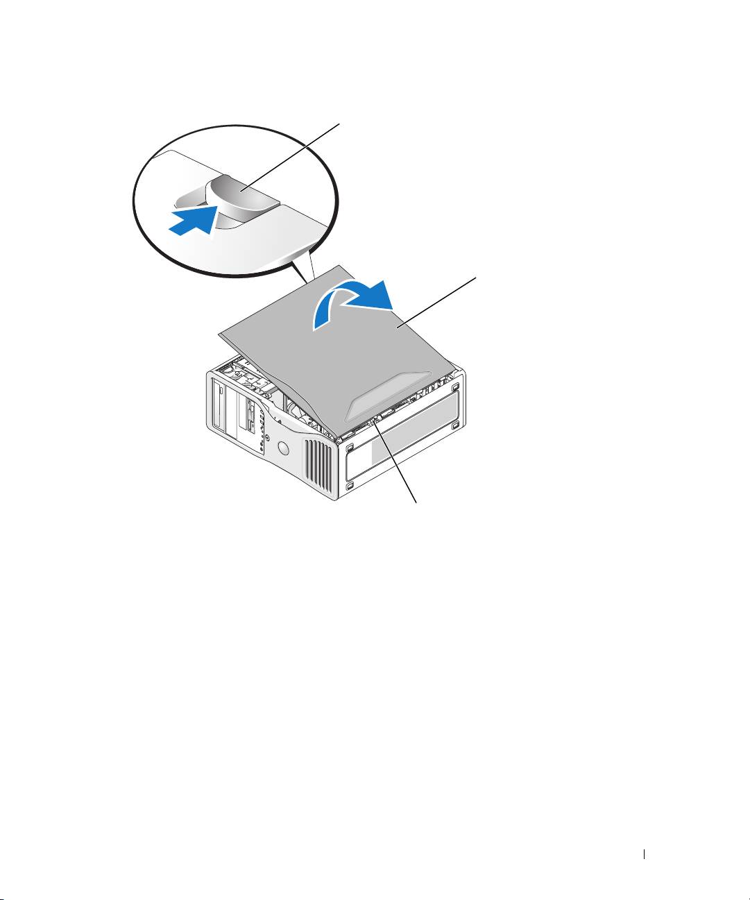
cover
computer cover
6
Locate the three hinge tabs on the edge of the computer.
7
Grip the sides of the computer cover and pivot the cover up, using the hinges as leverage
points.
8
Release the cover from the hinge tabs and set it aside in a secure location.
Caring for Your Computer
To help maintain your computer, follow these suggestions:
• To avoid losing or corrupting data, never turn off your computer when the hard drive light is on.
• Schedule regular virus scans using virus software.
• Manage hard drive space by periodically deleting unnecessary files and defragmenting the
drive.
• Back up files on a regular basis.
• Periodically clean your monitor screen, mouse, and keyboard (see your
User’s Guide
for more
information).
Quick Reference Guide 31
l
atc
h
cover
hinge tabs (3)
l
atc
h
re
l
ease

Solving Problems
Troubleshooting Tips
Perform the following checks when you troubleshoot your computer:
• If you added or removed a part before the problem started, review the installation procedures
and ensure that the part is correctly installed.
• If a peripheral device does not work, ensure that the device is properly connected.
• If an error message appears on the screen, write down the exact message. The message may
help technical support personnel diagnose and fix the problem(s).
• If an error message occurs in a program, see the program’s documentation.
www.dell.com | support.dell.com
• If the recommended action in the troubleshooting section is to see a section in your
User’s
Guide
, go to
support.dell.com
(on another computer if necessary) to access your
User’s
Guide.
Resolving Software and Hardware Incompatibilities
If a device is either not detected during the operating system setup or is detected but incorrectly
configured, you can use the Hardware Troubleshooter to resolve the incompatibility.
To resolve incompatibilities using the Hardware Troubleshooter:
1
Click the
Start
button and click
Help and Support
.
2
Ty p e
hardware troubleshooter
in the
Search
field and click the arrow to start the search.
3
Click
Hardware Troubleshooter
in the
Search Results
list.
4
In the
Hardware Troubleshooter
list, click
I need to resolve a hardware conflict on my
computer
, and click
Next
.
®
®
Using Microsoft
Windows
XP System Restore
The Microsoft Windows XP operating system provides System Restore to allow you to return your
computer to an earlier operating state (without affecting data files) if changes to the hardware,
software, or other system settings have left the computer in an undesirable operating state. See the
Windows Help and Support Center (see "Finding Information" on page 5) for information about
using System Restore.
NOTICE: Make regular backups of your data files. System Restore does not monitor your data files or
recover them.
Creating a Restore Point
1
Click the
Start
button and click
Help and Support
.
2
Click
System Restore
.
3
Follow the instructions on the screen.
32 Quick Reference Guide

Restoring the Computer to an Earlier Operating State
NOTICE: Before you restore the computer to an earlier operating state, save and close any open files
and exit any open programs. Do not alter, open, or delete any files or programs until the system
restoration is complete.
1
Click the
Start
button, point to
All Programs
→
Accessories
→
System Tools
, and then click
System Restore
.
2
Ensure that
Restore my computer to an earlier time
is selected and click
Next
.
3
Click a calendar date to which you want to restore your computer.
The
Select a Restore Point
screen provides a calendar that allows you to see and select restore
points. All calendar dates with available restore points appear in boldface type.
4
Select a restore point and click
Next
.
If a calendar date has only one restore point, then that restore point is automatically selected.
If two or more restore points are available, click the restore point that you prefer.
5
Click
Next
.
The
Restoration Complete
screen appears after System Restore finishes collecting data and
then the computer restarts.
6
After the computer restarts, click
OK
.
To change the restore point, you can either repeat the steps using a different restore point, or you
can undo the restoration.
Undoing the Last System Restore
NOTICE: Before you undo the last system restore, save and close all open files and exit any open
programs. Do not alter, open, or delete any files or programs until the system restoration is complete.
1
Click the
Start
button, point to
All Programs
→
Accessories
→
System Tools
, and then click
System Restore
.
2
Click
Undo my last restoration
and click
Next
.
3
Click
Next
.
The
System Restore
screen appears and the computer restarts.
4
After the computer restarts, click
OK
.
Enabling System Restore
If you reinstall Windows XP with less than 200 MB of free hard-disk space available, System
Restore is automatically disabled. To see if System Restore is enabled:
1
Click the
Start
button and click
Control
Panel
.
2
Click
Performance and Maintenance
.
3
Click
System
.
Quick Reference Guide 33

4
Click the
System Restore
tab.
5
Ensure that
Turn off System Restore
is unchecked.
Using the Last Known Good Configuration
1
Restart your computer and press <F8> when the message
Please select the
operating system to start
appears.
2
Highlight
Last Known Good Configuration
, press <Enter>, press <l>, and then select your
operating system when prompted.
Other Options to Help Resolve Additional Device or Software Conflicts
NOTICE: The following processes erase all of the information on your hard drive.
www.dell.com | support.dell.com
• Reinstall your operating system using the operating system installation guide and
Operating
System
CD.
During the operating system reinstallation, you can select to delete the existing partitions and
reformat your hard drive.
• Reinstall all drivers, beginning with the chipset, using the
Drivers and Utilities
CD
.
Dell Diagnostics
CAUTION: Before you begin any of the procedures in this section, follow the safety instructions in the
Product Information Guide.
When to Use the Dell Diagnostics
If you experience a problem with your computer, perform the checks in "Solving Problems" on
page 32 and run the Dell Diagnostics before you contact Dell for technical assistance.
It is recommended that you print these procedures before you begin.
NOTICE: The Dell Diagnostics works only on Dell™ computers. Using this program with other computers
can cause incorrect computer responses or result in error messages.
The Dell Diagnostics allow you to:
• Perform quick checks or extensive tests on one or all devices
• Choose how many times a test is run
• Display or print test results or save them in a file
• Suspend testing if an error is detected or terminate testing if a certain number of errors occur
• Access online
Help
screens that describe the tests and how to run them
• Read status messages that tell you whether tests completed successfully
• Receive error messages if problems are detected
34 Quick Reference Guide

Starting the Dell Diagnostics From Your Hard Drive
1
Turn on (or restart) your computer.
2
When the DELL™ logo appears, press <F12> immediately.
NOTE: If you see a message stating that no diagnostics utility partition has been found, see "Starting the
Dell Diagnostics From the Drivers and Utilities CD" on page 35.
If you wait too long and the operating system logo appears, continue to wait until you see the
Microsoft Windows desktop. Then shut down your computer and try again. For more
information on shutting down your computer, see your
User’s Guide.
3
When the boot device list appears, highlight
Boot to Utility Partition
and press <Enter>.
4
When the Dell Diagnostics
Main Menu
appears, select the test you want to run. For more
information on the tests, see your
User’s Guide.
Starting the Dell Diagnostics From the Drivers and Utilities CD
1
Insert the
Drivers and Utilities
CD.
2
Shut down and restart the computer. For more information on shutting down your computer,
see your
User’s Guide.
3
When the DELL logo appears, press <F12> immediately.
If you wait too long and the Windows logo appears, continue to wait until you see the
Windows desktop. Then shut down your computer and try again. For more information on
shutting down your computer, see your
User’s Guide.
NOTE: The next steps change the boot sequence for one time only. On the next start-up, the computer
boots according to the devices specified in system setup.
4
When the boot device list appears, highlight
IDE CD-ROM Device
and press <Enter>.
5
Select the
IDE CD-ROM Device
option from the CD boot menu.
6
Select the
Boot from CD-ROM
option from the menu that appears.
7
Ty p e
1
to start the ResourceCD menu.
8
Ty p e
2
to start the Dell Diagnostics.
9
Select
Run the 32 Bit Dell Diagnostics
from the numbered list. If multiple versions are listed,
select the version appropriate for your computer.
10
When the Dell Diagnostics
Main Menu
appears, select the test you want to run. For more
information on the tests, see your
User’s Guide.
Quick Reference Guide 35

Before You Start Testing
CAUTION: Before you begin any of the procedures in this section, follow the safety instructions in the
Product Information Guide.
• Turn on your printer if one is attached.
• Enter system setup, review your computer’s configuration information, and enable all of your
computer’s components and devices, such as connectors.
Beep Codes
Your computer might emit a series of beeps during start-up if the monitor cannot display errors or
problems. This series of beeps, called a beep code, identifies a problem. One possible beep code
www.dell.com | support.dell.com
(code 1-3-1) consists of one beep, a burst of three beeps, and then one beep. This beep code tells
you that the computer encountered a memory problem.
If a beep code is emitted, write it down and look it up in the following table.
Code Cause
1-1-2 Microprocessor register failure
1-1-3 NVRAM read/write failure
1-1-4 ROM BIOS checksum failure
1-2-1 Programmable interval timer failure
1-2-2 DMA initialization failure
1-2-3 DMA page register read/write failure
1-3 Video Memory Test failure
1-3-1 through 2-4-4 Memory not being properly identified or used
1-3-2 Memory problem
3-1-1 Slave DMA register failure
3-1-2 Master DMA register failure
3-1-3 Master interrupt mask register failure
3-1-4 Slave interrupt mask register failure
3-2-2 Interrupt vector loading failure
3-2-4 Keyboard Controller Test failure
3-3-1 NVRAM power loss
3-3-2 Invalid NVRAM configuration
3-3-4 Video Memory Test failure
3-4-1 Screen initialization failure
36 Quick Reference Guide
Code Cause
3-4-2 Screen retrace failure
3-4-3 Search for video ROM failure
4-2-1 No timer tick
4-2-2 Shutdown failure
4-2-3 Gate A20 failure
4-2-4 Unexpected interrupt in protected mode
4-3-1 Memory failure above address 0FFFFh
4-3-3 Timer-chip counter 2 failure
4-3-4 Time-of-day clock stopped
4-4-1 Serial or parallel port test failure
4-4-2 Failure to decompress code to shadowed memory
4-4-3 Math-coprocessor test failure
4-4-4 Cache test failure
Error Messages
NOTE: If the message is not listed, see the documentation for either the operating system or the program
that was running when the message appeared.
If an error occurs during start-up, a message may be displayed on the monitor identifying the
problem. See "Error Messages" in the
User’s Guide
for suggestions on resolving any problems.
Diagnostic Lights
CAUTION: Before you begin any of the procedures in this section, follow the safety instructions in the
Product Information Guide.
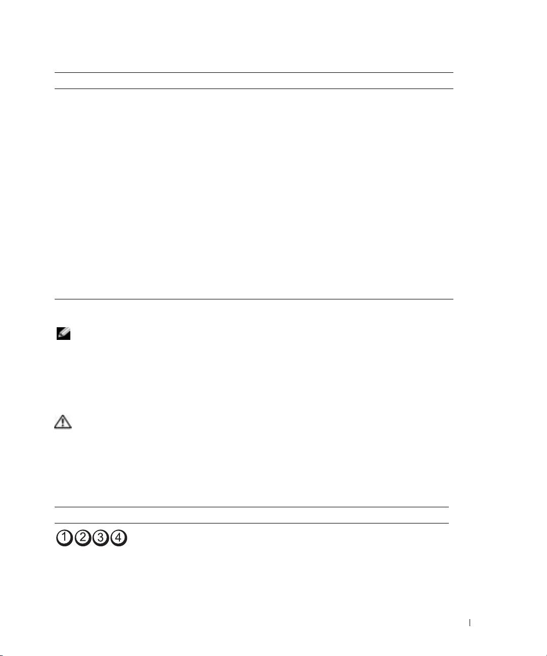
To help you troubleshoot a problem, your computer has four lights labeled "1," "2," "3," and "4" on
the front. The lights can be off or green. When the computer starts normally, the lights flash. After
the computer starts, all four lights display solid green briefly and then turn off to indicate normal
operation. If the computer malfunctions, the pattern of the lights identify the problem.
Light Pattern Problem Description Suggested Resolution
The computer is in a normal off
Plug the computer into a working
condition or a possible pre-BIOS failure
electrical outlet and press the power
has occurred.
button.
NOTE: The diagnostic lights turn off after
a short time if the computer is in a normal
operating condition after POST.
Quick Reference Guide 37

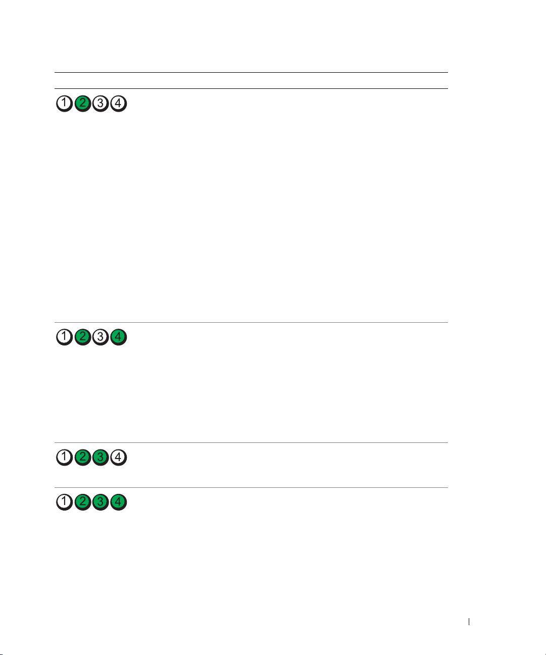
Light Pattern Problem Description Suggested Resolution
A possible BIOS failure has occurred; the
Run the BIOS Recovery utility, wait for
computer is in the recovery mode.
recovery completion, and then restart
the computer.
A possible processor failure has occurred. Reinstall the processor and restart the
computer.
Memory modules are detected, but a
1
Reseat the memory modules to ensure
memory failure has occurred.
that your computer is successfully
communicating with the memory.
2
Restart the computer.
www.dell.com | support.dell.com
3
If the problem still exists, remove all
the memory modules and install one
memory module in memory module
connector 4.
4
Restart the computer.
The following message appears:
Alert! Operating in Debug
Mode. Please Populate
Memory in Pairs for Normal
Operation
.
5
Press <F1> to boot to the operating
system.
6
Run the Dell Diagnostics. See page 34
for instructions.
7
If the memory module passes, shut
down the computer, remove the
memory module, and then repeat the
process with the remaining memory
modules until a memory error occurs
during start-up or diagnostic testing.
If the first memory module tested is
defective, repeat the process with the
remaining modules to ensure that the
remaining modules are not defective.
8
When the defective memory module
is identified, contact Dell for a
replacement. For instructions on
contacting Dell, see your
User’s Guide
.
NOTE: If necessary, the computer can
operate in debug mode until new memory
modules are installed.
38 Quick Reference Guide
Light Pattern Problem Description Suggested Resolution
A possible expansion card failure has
1
Determine if a conflict exists by
occurred.
removing a card (not the graphics
card) and then restarting the
computer. For more information on
removing a card, see your
User’s
Guide
.
2
If the problem persists, reinstall the
card that you removed, remove a
different card, and then restart the
computer.
3
Repeat this process for each card. If
the computer starts normally,
troubleshoot the last card removed
from the computer for resource
conflicts (see"Resolving Software and
Hardware Incompatibilities" on
page 32).
4
If the problem persists, contact Dell.
For instructions on contacting Dell,
see your
User’s Guide
.
A possible graphics card failure has
• If the computer has a graphics card,
occurred.
remove the card, reinstall it, and then
restart the computer.
• If the problem still exists, install a
graphics card that you know works and
restart the computer.
• If the problem persists or the
computer has integrated graphics,
contact Dell. For instructions on
contacting Dell, see your
User’s Guide.
A possible floppy or hard drive failure
Reseat all power and data cables and
has occurred.
restart the computer.
A possible USB failure has occurred. Reinstall all USB devices, check cable
connections, and then restart the
computer.
Quick Reference Guide 39

Light Pattern Problem Description Suggested Resolution
No memory modules are detected. 1
Reseat the memory modules to ensure
that your computer is successfully
communicating with the memory.
2
Restart the computer.
3
If the problem still exists, remove all
the memory modules and install one
memory module in memory module
connector 4.
4
Restart the computer.
The following message appears:
Alert! Operating in Debug
www.dell.com | support.dell.com
Mode. Please Populate
Memory in Pairs for Normal
Operation
.
5
Press <F1> to boot to the operating
system.
6
Run the Dell Diagnostics. See page 34
for instructions.
7
If the memory module passes, shut
down the computer, remove the
memory module, and then repeat the
process with the remaining memory
modules until a memory error occurs
during start-up or diagnostic testing.
If the first memory module tested is
defective, repeat the process with the
remaining modules to ensure that the
remaining modules are not defective.
8
When the defective memory module
is identified, contact Dell for a
replacement.For instructions on
contacting Dell, see your
User’s Guide.
NOTE: If necessary, the computer can
operate in debug mode until new memory
modules are installed.
System board failure has occurred. Contact Dell for technical assistance.
For instructions on contacting Dell, see
your User’s Guide.
40 Quick Reference Guide
