Kenwood KRC-394: Connecting Wires to Terminals
Connecting Wires to Terminals: Kenwood KRC-394
KRC-394(E2)_U.S r1 02.9.26 7:29 PM Page 25
Connecting Wires to Terminals
■ Connector Function Guide ■ Plug Setting
2WARNING
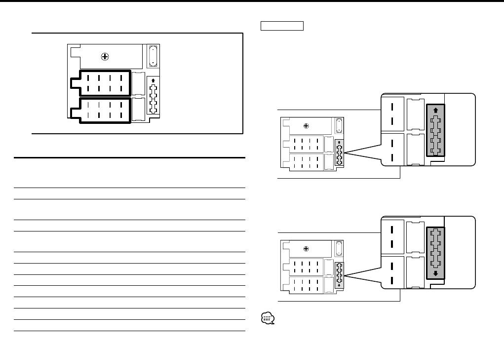
Connecting the ISO Connector
The pin arrangement for the ISO connectors depends on the type
of vehicle you drive. Make sure to make the proper connections
10
to prevent damage to the unit.
1 The A-7 pin of the vehicle's ISO connector is linked with the
1
3
5
7
ignition, and the A-4 pin is connected to the constant power
Connector B
supply. (Default setting)
2
4
6
8
1
3
5
7
Connector A
2
4
6
8
10
Pin Numbers Plug Functions
for ISO Connectors setting*
<External Power Connector>
A–4 1 Battery
2 Ignition (ACC)
2 The A-7 pin of the vehicle's ISO connector is connected to
A–5 Power Control
the constant power supply, and the A-4 pin is linked to the
A–7 1 Ignition (ACC)
ignition.
2 Battery
A–8 Earth (Ground) Connection
<Speaker Connector>
10
B–1 Rear Right (+)
B–2 Rear Right (–)
B–3 Front Right (+)
B–4 Front Right (–)
B–5 Front Left (+)
B–6 Front Left (–)
B–7 Rear Left (+)
• If both the A-7 pin and A-4 pin are connected to the vehicle constant
power supply, use Plug setting 2.
B–8 Rear Left (–)
• If the A-7 pin is connected to the vehicle constant power supply,
*Plug setting: See right side.
and the A-4 pin isn't connected to anything, wire the unit using the
Wiring harness (Accessory 1).
— 25 —— 25 —
Оглавление
- CASSETTE RECEIVER
- Contents
- Safety precautions
- Safety precautions About RDS
- General features
- Tuner features General features
- RDS features
- RDS features
- Tuner features
- Tuner features
- External disc control features
- External disc control features
- Menu system
- Menu system
- Menu system
- Accessories
- Connecting Wires to Terminals
- Connecting Wires to Terminals
- Connecting Wires to Terminals Installation
- Troubleshooting Guide
- Troubleshooting Guide
- Specifications
- Cодержание
- Меры предосторожности
- Меры предосторожности O RDS
- Общие характеристики
- Cвойства тюнера Общие характеристики
- Cвойства RDS
- Cвойства RDS
- Cвойства тюнера
- Cвойства тюнера
- Функции управления внешним диском
- Функции управления внешним диском
- Система меню
- Система меню
- Система меню
- Принадлежности
- Подсоединение кабелей к гнездам для подключения
- Подсоединение кабелей к гнездам для подключения Установка
- Поиск и устранение неисправностей
- Поиск и устранение неисправностей
- Технические характеристики
- Treść
- Środki ostrożności
- Środki ostrożności Informacje o RDS
- Ogólne możliwości
- Możliwości tunera Ogólne możliwości
- Możliwości RDS
- Możliwości RDS
- Możliwości tunera
- Możliwości tunera
- Możliwości sterowania zewnętrznymi płytami
- Możliwości sterowania zewnętrznymi płytami
- Menu systemu
- Menu systemu
- Menu systemu
- Akcesoria
- Podłączanie przewodów do końcówek
- Podłączanie przewodów do końcówek Instalacja
- Przewodnik wykrywania i usuwania usterek
- Przewodnik wykrywania i usuwania usterek
- Dane techniczne
- Obsah
- Bezpečnostní pokyny
- Bezpečnostní pokyny O RDS
- Obecné funkce
- Funkce tuneru Obecné funkce
- Funkce RDS
- Funkce RDS
- Funkce tuneru
- Funkce tuneru
- Funkce ovládání externího disku
- Funkce ovládání externího disku
- Systém menu
- Systém menu
- Systém menu
- Příslušenství
- Připojování kabelů ke svorkám
- Připojování kabelů ke svorkám Instalace
- Przewodnik wykrywania i usuwania usterek
- Przewodnik wykrywania i usuwania usterek
- Specifikace


