Indesit FGIM-K-IX-S: Installation
Installation: Indesit FGIM-K-IX-S
GB
19
Installation
!
Please keep this instruction booklet in a safe place for
future reference. If the appliance is sold, given away or
moved, please make sure the booklet is also passed on to
the new owners so that they may benefit from the advice
contained within it.
!
Please read this instruction manual carefully: it contains
important information concerning the safe operation,
installation and maintenance of the appliance.
Positioning
!
Do not let children play with the packaging material; it
should be disposed of in accordance with local separated
waste collection standards (see Precautions and tips).
!
The appliance must be installed by a qualified professional in
accordance with the instructions provided. Incorrect installation
may damage property or cause harm to people or animals.
!
This unit may be installed and used only in permanently
ventilated rooms in accordance with current National
Regulations. The following requirements must be observed:
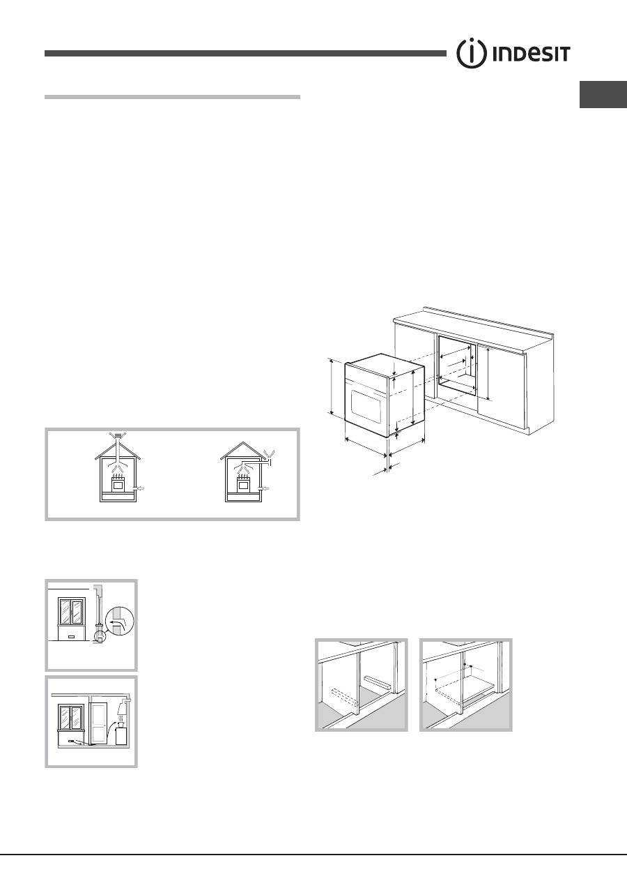
• The room must be equipped with an air extraction system
that expels any combustion fumes. This may consist of
a hood or an electric fan that automatically starts each
time the appliance is switched on.
In a chimney stack or branched flue.
(exclusively for cooking appliances)
Directly to
the Outside
• The room must also allow proper air circulation, as air is
needed for combustion to occur normally. The flow of air
must not be less than 2 m
3
/h per kW of installed power.
The air circulation system may
take air directly from the outside
by means of a pipe with an inner
cross section of at least 100 cm
2
;
the opening must not be vulnerable
to any type of blockages.
The system can also provide the air
needed for combustion indirectly,
i.e. from adjacent rooms fitted with
air circulation tubes as described
above. However, these rooms must
not be communal rooms, bedrooms
or rooms that may present a fire
hazard.
• Liquid petroleum gas sinks to the floor as it is heavier
than air. Therefore, rooms containing LPG cylinders must
also be equipped with vents to allow gas to escape in
the event of a leak. As a result LPG cylinders, whether
A
Examples of
ventilation holes
for comburant air.
Enlarging the ventilation slot
between window and floor.
Adjacent
Room
Room to be
Vented
partially or completely full, must not be installed or stored
in rooms or storage areas that are below ground level
(cellars, etc.). It is advisable to keep only the cylinder
being used in the room, positioned so that it is not subject
to heat produced by external sources (ovens, fireplaces,
stoves, etc. ) which could raise the temperature of the
cylinder above 50°C.
Built-in appliances
Use an appropriate cabinet to ensure that the appliance
operates properly:
• the panels adjacent to the oven must be made of heat-
resistant material.
• cabinets with a veneer exterior must be assembled with
glues which can withstand temperatures of up to 100°C.
• to install the oven
under the counter
(see diagram) or
in a
kitchen unit
, the cabinet must have the following
dimensions:
595 mm.
595 mm.
25 mm.
545 mm.
5 mm.
567 mm.
23 mm.
575-585 mm.
45 mm.
558 mm.
547 mm. min.
!
The appliance must not come into contact with electrical
parts once it has been installed.
The indications for consumption given on the data plate
have been calculated for this type of installation.
Ventilation
To ensure adequate ventilation, the back panel of the
cabinet must be removed. It is advisable to install the oven
so that it rests on two strips of wood, or on a completely
flat surface with an opening of at least 45 x 560 mm (see
diagrams).
560 mm
.
45 mm.
Centring and fixing
Secure the appliance to the cabinet by opening the oven door
and inserting 4 screws into the 4 holes on the outer frame.
20
GB
!
All parts which ensure the safe operation of the appliance
must not be removable without the aid of a tool.
Electrical connection
Ovens equipped with a three-pole power supply cable are
designed to operate with alternating current at the voltage
and frequency indicated on the data plate located on the
appliance (see below).
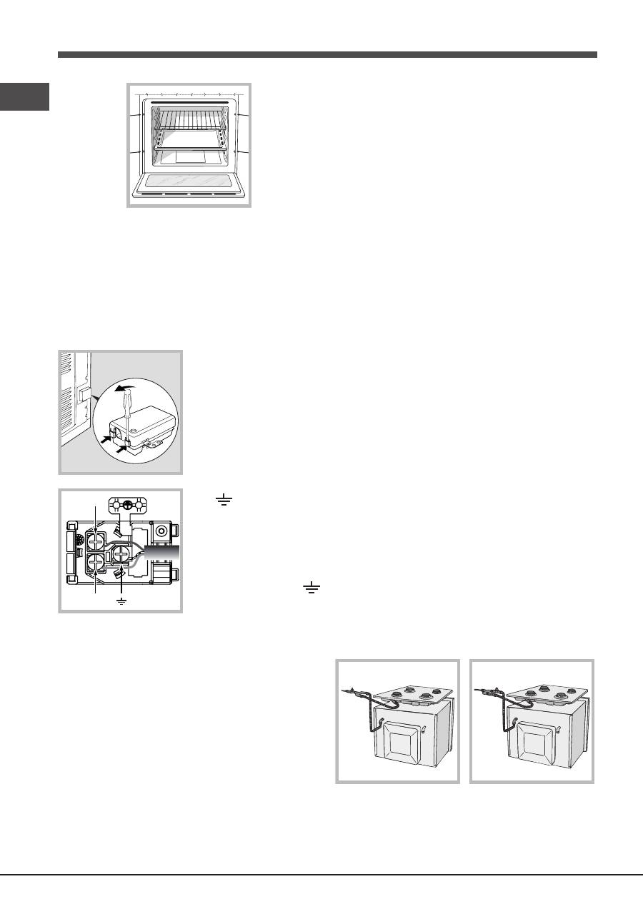
Fitting the power supply cable
1. Open the terminal board
by inserting a screwdriver
into the side tabs of the
cover. Use the screwdriver
as a lever by pushing it
down to open the cover (see
diagram).
2. Install the power supply
cable by loosening the
cable clamp screw and the
three wire contact screws
L-N-
.
Connect the wires to the
corresponding terminals:
the Blue wire to the terminal
marked (N), the Brown wire
to the terminal marked (L)
and the Yellow/Green wire
to the terminal marked
(see diagram).
3. Secure the cable by fastening the clamp screw.
4. Close the cover of the terminal board.
Connecting the supply cable to the mains
Install a standardised plug corresponding to the load
indicated on the data plate (see table).
The appliance must be directly connected to the mains using
an omnipolar switch with a minimum contact opening of 3
mm installed between the appliance and the mains. The
switch must be suitable for the charge indicated and must
comply with current electrical regulations (the earthing wire
must not be interrupted by the switch). The supply cable
must be positioned so that it does not come into contact
with temperatures higher than 50°C at any point (the back
panel of the oven, for example).
!
The installer must ensure that the correct electrical
connection has been performed and that it is fully compliant
with safety regulations.
L
N
N
L
Before connecting the appliance to the power supply, make
sure that:
• the appliance is earthed and the plug is compliant with
the law.
• the socket can withstand the maximum power of the
appliance, which is indicated on the data plate.
• the voltage is in the range between the values indicated
on the data plate.
• the socket is compatible with the plug of the appliance.
If the socket is incompatible with the plug, ask an
authorised technician to replace it. Do not use extension
cords or multiple sockets.
!
Once the appliance has been installed, the power supply
cable and the electrical socket must be easily accessible.
!
The cable must not be bent or compressed.
!
The cable must be checked regularly and replaced by
authorised technicians only (see Assistance).
!
The manufacturer declines any liability should these
safety measures not be observed.
Gas connection
The appliance should be connected to the main gas supply
or to a gas cylinder in compliance with current National
regulations. Before carrying out the connection, make sure
the cooker is compatible with the gas supply you wish to
use. If this is not the case, follow the instructions indicated
in the paragraph “Adapting to different types of gas.”
When using liquid gas from a cylinder, install a pressure
regulator that complies with current National regulations.
!
Check that the pressure of the gas supply is consistent
with the values indicated in Table 1 (“Burner and nozzle
specifications”) since this will ensure the safe operation
and longevity of your appliance while maintaining efficient
energy consumption.
!
Should you need to install a gas hob on top of a built-in gas
oven, it is strictly forbidden to connect the two or to use a
single cut-off tap. The two appliances should be connected
separately, and each one should have its own stop tap
in order to make them completely independent from one
another (see figures).
NO
OK
Connection with a rigid pipe (copper or steel)
!
Connection to the gas system must be carried out in such a
way as not to place any strain of any kind on the appliance.
There is an adjustable
L
-shaped pipe fitting on the appliance
GB
21
supply ramp and this is fitted with a seal in order to prevent
leaks. The seal must always be replaced after rotating the pipe
fitting (the seal is provided with the appliance). The gas supply
pipe fitting is a threaded 1/2 gas cylindrical male attachment.
Connecting a flexible jointless stainless steel pipe to a
threaded attachment
The gas supply pipe fitting is a threaded 1/2 gas cylindrical male
attachment. These pipes must be installed so that they are never
longer than 2000 mm when fully extended. Once connection has
been carried out, make sure that the flexible metal pipe does
not touch any moving parts and is not compressed.
!
Only use pipes and seals that comply with current National
regulations.
Checking the tightness of the connection
!
When installation has been completed, check the pipe
fittings for leaks using a soapy solution. Never use a flame.
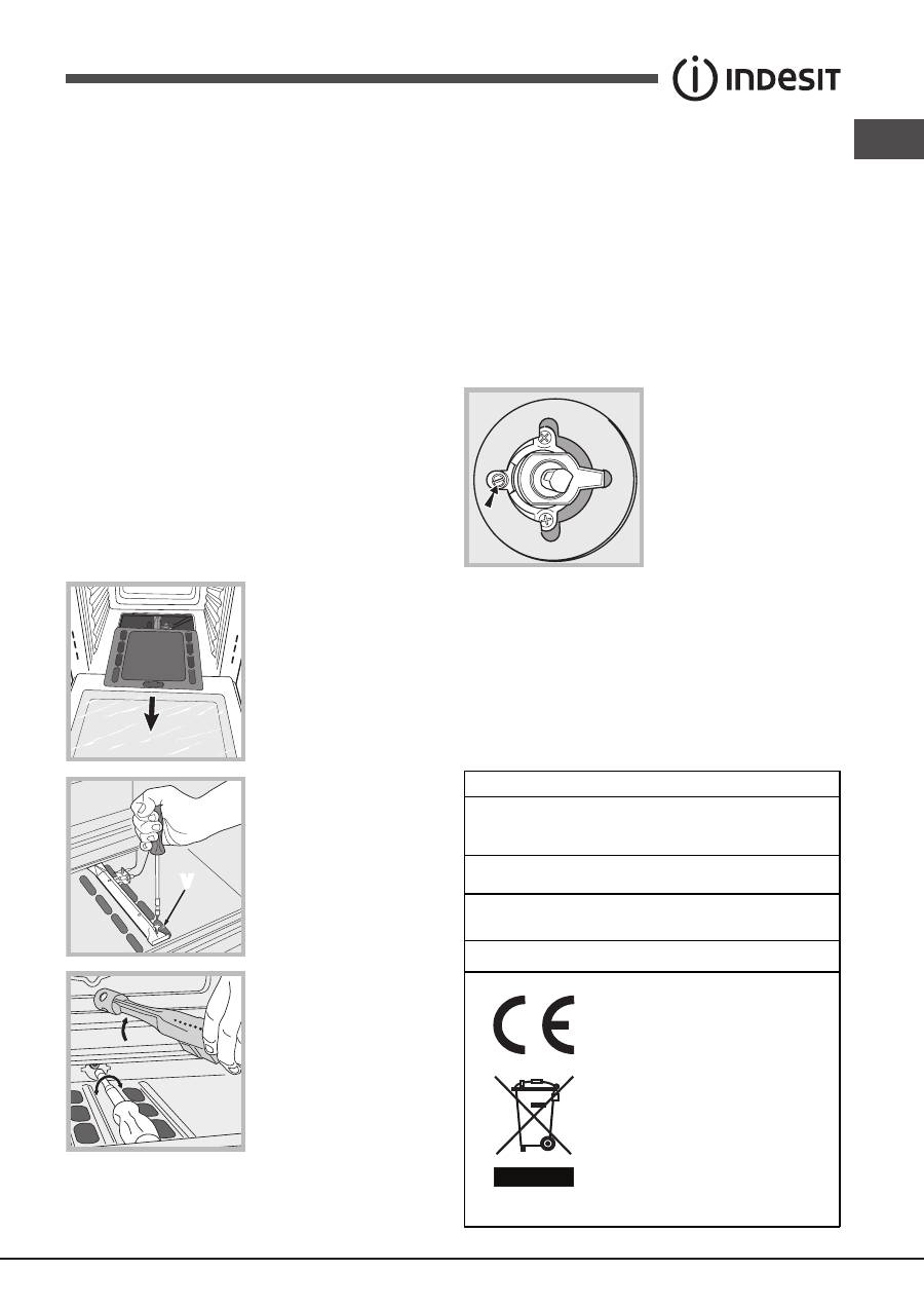
Adapting to different types of gas
In order to adapt the oven to a type of gas other than the
type for which it was manufactured (indicated on the label),
follow these simple steps:
• Replacing the oven burner nozzle
1. Open the oven door fully.
2. Slide out the bottom of the
oven.
V
3. Unscrew the burner
fastening screws.
4. Remove screw “
V
” and
then the oven burner.
5. Unscrew the oven burner
nozzle using the special
socket spanner for the
nozzles, or better still a 7 mm
socket spanner, and replace
it with a nozzle suited to the
new type of gas (see Table 1).
6. Replace all the parts, following the steps described above
in the reverse order.
!
Take particular care when handling the spark plug
wires and the thermocouple pipes.
• Primary air regulation for the oven burner
The burner was designed not to need any adjustments to
the primary air.
• Setting the oven burner to minimum
1. Turn the knob first to the Max setting for about 10 minutes
and then to Min.
2. Remove the knob.
3. Remove the disk fastened to the control panel.
4. Adjust the screw located outside the thermostat cock pin
until the flame is small but steady (the flame can be seen
through the slots on the oven bottom).
5. Make sure the burner does
not switch off when you turn
the knob from Max to Min
quickly, or when you open
and close the oven door
quickly.
!
If the appliance is connected to liquid gas, the regulation
screw must be fastened as tightly as possible.
!
Once this procedure is finished, replace the old rating
sticker with one indicating the new type of gas used. This
sticker is available from any of our Service Centres.
!
If the gas pressure is different from the recommended
pressure, a suitable pressure regulator must be fitted to the
inlet pipe in accordance with current National Regulations.
DATA PLATE
Dimensions
width 43.5 cm
height 31 cm
depth 43.5 cm
Volume
58 l
Electrical
connections
see data plate
Gas features
see data plate
This appliance conforms to the
following European Economic
Community directives:
2006/95/EEC dated 12/12/06
(Low Voltage) and subsequent
amendments - 2004/108/EEC
dated 15/12/04 (Electromagnetic
compatibility) and subsequent
amendments - 93/68/EEC dated
22/07/93 and subsequent
amendments. 2009/142/EEC
dated 30/11/09 (Gas) and
subsequent amendments.
2012/19/EC and subsequent
amendments.
Оглавление
- Довідник користувача
- Avvertenze
- Advertencias
- Предупреждения
- Assistenza
- Assistência
- Descrizione dell’apparecchio
- Описание изделия
- Descrizione dell’apparecchio
- Installazione
- Avvio e utilizzo
- Programmi
- Precauzioni e consigli
- Installation
- Start-up and use
- Cooking modes
- Precautions and tips
- Instalación
- Puesta en funcionamiento y uso
- Programas
- Precauciones y consejos
- Instalação
- Início e utilização
- Programas
- Precauções e conselhos
- Установка
- Включение и эксплуатация
- Программы
- Предосторожности и рекомендации
- Техническое обслуживание и уход
- Установлення
- Запуск і використання
- Програми
- Запобіжні заходи та поради
