Dell LATITUDE D400: ErrorMessagesandFlashCodes:Dell™Latitude™CS/CS
ErrorMessagesandFlashCodes:Dell™Latitude™CS/CS: Dell LATITUDE D400
Back to Contents Page
ErrorMessagesandFlashCodes:Dell™Latitude™CS/CS
x
Portable Computers User's
Guide
Error Messages
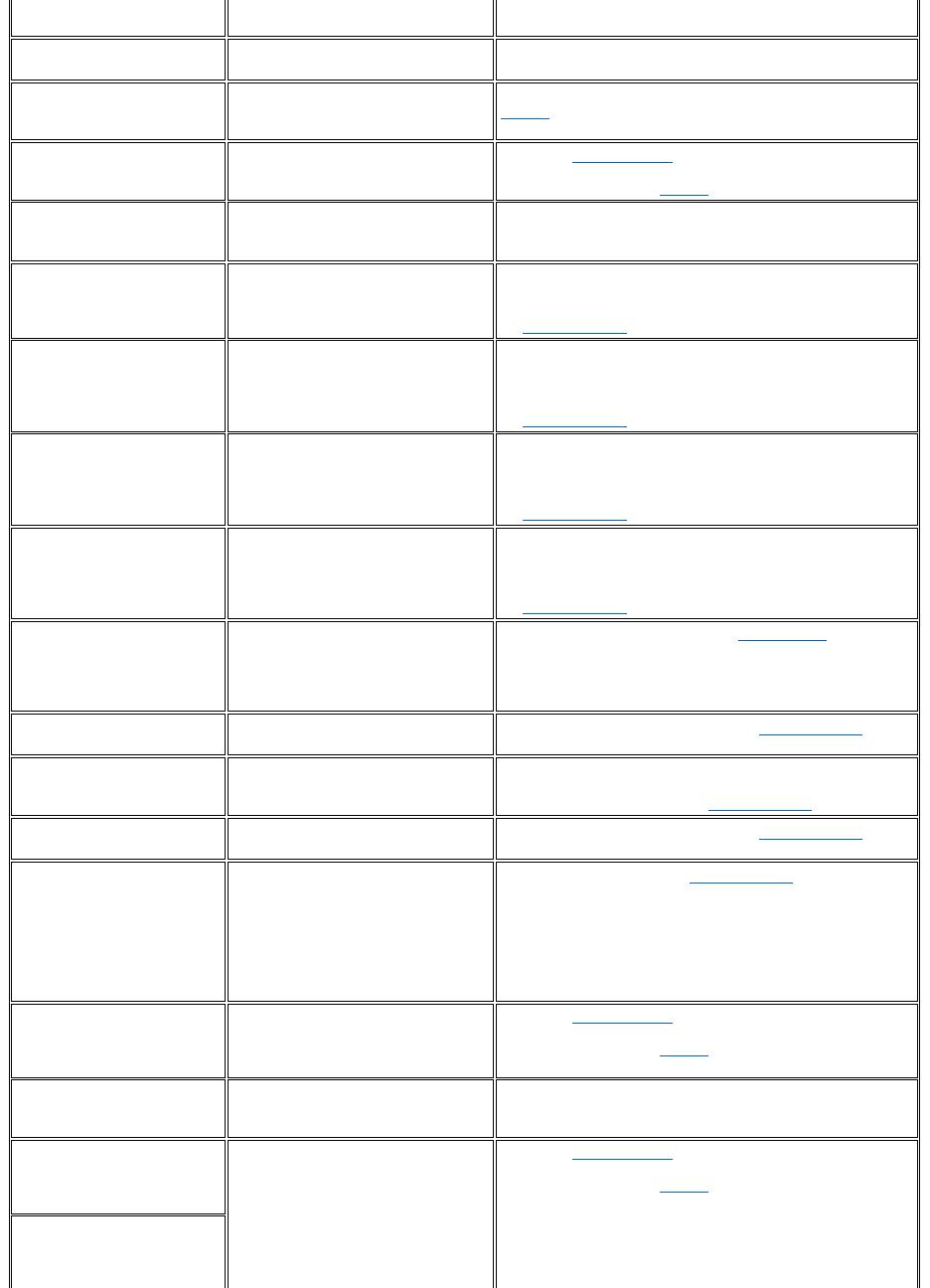
Your application programs, operating system, and the computer itself can identify problems and alert you to them. When this occurs, a message
may appear on the computer's display or on an external monitor (if one is attached), or a flash code may be emitted.
If an error message appears on the display or external monitor, make a note of the message. For an explanation of the message and suggestions
for correcting any errors, see Table 1. The messages are listed alphabetically.
Table 1. System Error Messages
Error Messages
Memory Allocations
System Flash Codes
I/O Memory Map
Avoiding Interrupt Assignment Conflicts
NOTE: If the message is not listed in Table 1, see the documentation for the application program or the operating system
documentation for an explanation of the message and a recommended action.
Message
Cause
Action
Auxiliary device
failure
The touch pad or external PS/2 mouse
may be faulty.
If you are using an external mouse only, check the connection for a
loose or improperly connected cable. If the problem persists,
enable the Pointing Device option. If the problem persists, call
Dell for technical assistance.
Bad command or file
name
The command you entered does not
exist or is not in the pathname you
specified.
Make sure that you have typed the command correctly, placed
spaces in the proper location, and used the correct pathname.
Cache disabled due to
failure
The primary cache internal to the
microprocessor has failed.
Call Dell for technical assistance.
CD-ROM drive
controller failure 1
The CD-ROM drive does not respond to
commands from the computer.
Turn off the computer and detach the CD-ROM drive from the
media bay connector. Reboot the computer. Turn off the computer
again, reattach the CD-ROM drive to the computer, and verify the
media-bay cable connection to the back of the CD-ROM drive.
Reboot the computer. If the problem persists, run the CD-ROM
Drive tests in the Dell Diagnostics.
Data error
The diskette or hard-disk drive cannot
read the data.
Run the appropriate utility to check the file structure of the diskette
drive or hard-disk drive. See the documentation that came with
your operating system.
Decreasing available
memory
One or more memory modules may be
faulty or improperly seated.
Reseat the memory module in the upgrade socket. If the problem
persists, remove the memory module from the upgrade socket. If
the problem still persists, call Dell for technical assistance.
Disk C: failed
initialization
The hard-disk drive failed initialization.
Remove and reseat the hard-disk drive, and reboot the computer.
If the problem persists, boot from the diagnostics diskette and run
the Hard-Disk Drive tests.
Diskette drive 0 seek
failure
A cable may be loose, or the system
configuration information may not match
the hardware configuration.
Check and reseat the diskette drive cable. If the problem persists,
run the Diskette Drive tests in the Dell Diagnostics and check the
setting for the appropriate drive (Diskette Drive A or Diskette
Drive B) in the System Setup program. If the problem cannot be
corrected, call Dell for technical assistance.
Diskette read failure
A cable may be loose, or the diskette
may be faulty.
If the diskette-drive access indicator lights up, try a different
diskette.
Diskette subsystem
reset failed
The diskette drive controller may be
faulty.
Run the Diskette Drive tests in the Dell Diagnostics.
Diskette write-
protected
Because the diskette is write-protected,
the operation cannot be completed.
Slide the write-protect notch up.
Drive not ready
No diskette is in the diskette drive, or no
hard-disk drive is in the drive bay. The
operation requires a diskette in the drive
Put a diskette in the drive, or push the diskette all the way into the
drive until the eject button pops out. Or, install a hard-disk drive in
the drive bay.
or a hard-disk drive in the bay before it
can continue.
Error reading PCMCIA
card
The computer cannot identify the PC
Card.
Reseat the card or try another PC Card that you know works.
Extended memory size
has changed
The amount of memory recorded in
NVRAM does not match the memory
installed in the computer.
Reboot the computer. If the error appears on the display again,
call Dell for technical assistance.
Gate A20 failure
An installed memory module may be
loose.
Reseat the memory module in the upgrade socket. If the problem
persists, remove the memory module from the upgrade socket. If
the problem still persists, call Dell for technical assistance.
General failure
The operating system is unable to carry
out the command.
This message is usually followed by specific information—for
example, Printer out of paper. Respond by taking the
appropriate action.
Hard-disk drive
configuration error
The computer cannot identify the drive
type.
Turn off the computer, remove the drive, and boot the computer
from a bootable diskette. Then turn off the computer, reinstall the
drive, and reboot the computer. Run the Hard-Disk Drive tests in
the Dell Diagnostics.
Hard-disk drive
controller failure 0
The hard-disk drive does not respond to
commands from the computer.
Turn off the computer, remove the drive, and boot the computer
from a bootable diskette. Then turn off the computer again,
reinstall the drive, and reboot the computer. If the problem
persists, try another drive. Then run the Hard-Disk Drive tests in
the Dell Diagnostics.
Hard-disk drive
failure
The hard-disk drive does not respond to
commands from the computer.
Turn off the computer, remove the drive, and boot the computer
from a bootable diskette. Then turn off the computer again,
reinstall the drive, and reboot the computer. If the problem
persists, try another drive. Then run the Hard-Disk Drive tests in
the Dell Diagnostics.
Hard-disk drive read
failure
The hard-disk drive may be faulty.
Turn off the computer, remove the drive, and boot the computer
from a bootable diskette. Then turn off the computer again,
reinstall the drive, and reboot the computer. If the problem
persists, try another drive. Then run the Hard-Disk Drive tests in
the Dell Diagnostics.
Invalid configuration
information-please run
System Setup Program
The system configuration information
does not match the hardware
configuration. This message is most
likely to occur after a memory module is
installed.
Correct the appropriate options in the System Setup program.
Keyboard clock line
failure
A cable or connector may be loose, or
the keyboard may be faulty.
Run the Keyboard Controller test in the Dell Diagnostics.
Keyboard controller
failure
A cable or connector may be loose, or
the keyboard may be faulty.
Reboot the computer, and avoid touching the keyboard or the
mouse during the boot routine. If the problem persists, run the
Keyboard Controller test in the Dell Diagnostics.
Keyboard data line
failure
A cable or connector may be loose, or
the keyboard may be faulty.
Run the Keyboard Controller test in the Dell Diagnostics.
Keyboard stuck key
failure
If an external keyboard or keypad is
being used, a cable or connector may be
loose or the keyboard may be faulty. If
the integrated keyboard is being used,
the keyboard may be faulty.
A key on the integrated keyboard or
external keyboard may have been
pressed while the computer was booting.
Run the Stuck Key test in the Dell Diagnostics.
Memory address line
failure at address,
read value expecting
value
An installed memory module may be
faulty or improperly seated.
Reseat the memory module in the upgrade socket. If the problem
persists, remove the memory module from the upgrade socket. If
the problem still persists, call Dell for technical assistance.
Memory allocation
error
The software you are attempting to run is
conflicting with the operating system,
another application program, or a utility.
Turn off the computer, wait 30 seconds, and then restart it. Try to
run the program again. If the problem persists, contact the
software company.
Memory data line
failure at address,
read value expecting
value
An installed memory module may be
faulty or improperly seated.
Reseat the memory module in the upgrade socket. If the problem
persists, remove the memory module from the upgrade socket. If
the problem still persists, call Dell for technical assistance.
Memory double word
logic failure at
address, read value
expecting value
System Flash Codes
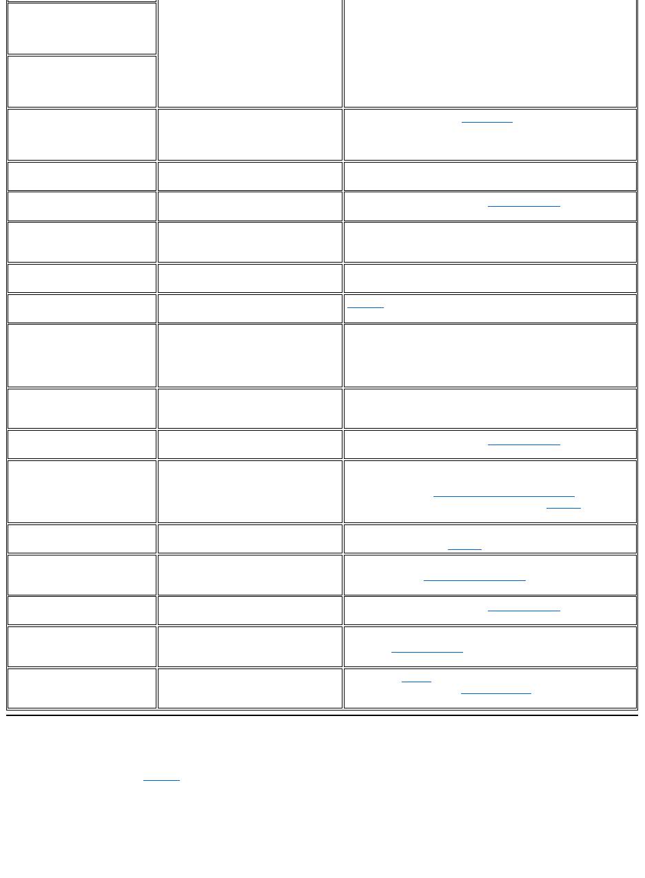
When errors that occur during the boot routine cannot be reported on the display or on an external monitor (if attached), the Num Lock, Caps Lock,
and Scroll Lock indicators (see Figure 1) may flash together in a pattern of lights (or flash code) that identifies the problem. For example, one
flash, followed by a second flash, and then a burst of three flashes (code 1-1-3) means that the computer was unable to read the data in nonvolatile
random-access memory (NVRAM). This information is important to the Dell support staff if you need to call for technical assistance.
The Num Lock, Caps Lock, and Scroll Lock indicators flash briefly when the computer is turned on. The flash codes, if needed, occur after the boot
routine.
Figure 1. Flash Code Indicators
Memory odd/even logic
failure at address,
read value expecting
value
Memory write/read
failure at address,
read value expecting
value
No boot device
available
The computer cannot find the diskette or
hard-disk drive.
If the diskette drive is your boot device, make sure that there is a
bootable diskette in the drive. If the hard-disk drive is your boot
device, make sure that the drive is installed, properly seated, and
partitioned as a boot device.
No boot sector on
hard-disk drive
The operating system may be corrupted.
Reinstall your operating system. See the documentation that came
with your operating system.
No timer tick
interrupt
A chip on the system board may be
malfunctioning.
Run the System Set tests in the Dell Diagnostics.
Non-system disk or
disk error
The diskette in drive A or your hard-disk
drive does not have a bootable
operating system installed on it.
If you are trying to boot from the diskette, replace it with one that
has a bootable operating system.
Not a boot diskette
There is no operating system on the
diskette.
Boot the computer with a diskette that contains an operating
system.
Optional ROM bad
checksum
The optional ROM apparently failed.
Call Dell for technical assistance.
Sector not found
The operating system cannot locate a
sector on the diskette or hard-disk drive.
You probably have a bad sector or
corrupted FAT on the diskette or hard-
disk drive.
Run the appropriate utility to check the file structure on the diskette
or hard-disk drive. If a large number of sectors are defective, back
up the data (if possible), and then reformat the diskette or hard-
disk drive.
Seek error
The operating system cannot find a
specific track on the diskette or hard-
disk drive.
If the error is on the diskette drive, try another diskette in the drive.
Shutdown failure
A chip on the system board may be
malfunctioning.
Run the System Set tests in the Dell Diagnostics.
Time-of-day clock lost
power
Data stored in NVRAM has become
corrupted.
Connect your computer to an electrical outlet to charge the battery.
If the problem persists, try to restore the data. To restore the data,
press <Fn><F1> to enter the System Setup program. Then
immediately exit it. If the message reappears, call Dell for
technical assistance.
Time-of-day clock
stopped
The reserve battery that supports the
data stored in NVRAM may be dead.
Connect your computer to an electrical outlet to charge the battery.
If the problem persists, call Dell for technical assistance.
Time-of-day not set-
please run the System
Setup program
The time or date stored in the System
Setup program does not match the
system clock.
Correct the settings for the Date and Time options. (For
instructions, see "System Setup Program.")
Timer chip counter 2
failed
A chip on the system board may be
malfunctioning.
Run the System Set tests in the Dell Diagnostics.
Unexpected interrupt
in protected mode
The keyboard controller may be
malfunctioning, or an installed memory
module may be loose.
Run the System Memory tests and the Keyboard Controller
test in the Dell Diagnostics.
Warning: Battery is
critically low.
The battery is running out of charge.
Replace the battery, or connect the computer to an electrical
outlet. Otherwise, activate suspend-to-disk mode or turn off the
computer.
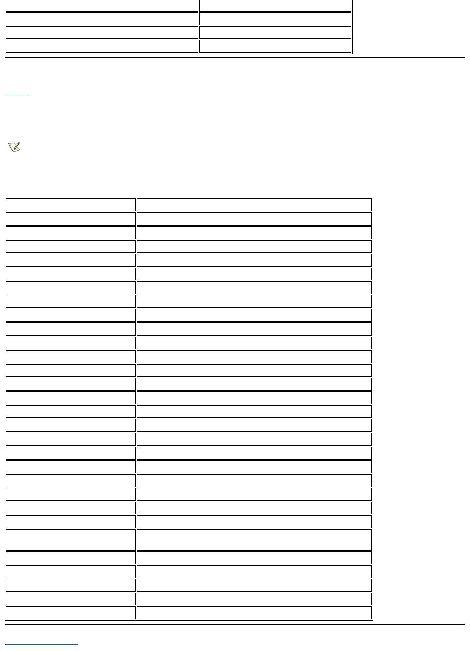
When the computer emits a flash code, write it down on a copy of the Diagnostics Checklist and then look up its cause and meaning in Table 2. If
you are unable to resolve the problem, use the Dell Diagnostics to identify a more serious cause. If you are still unable to resolve the problem, call
Dell for technical assistance.
Table 2. Flash Codes and Corrective Actions
Avoiding Interrupt Assignment Conflicts
Problems can arise if two devices attempt to use the same interrupt request (IRQ) line. To avoid this type of conflict, check the documentation for
the default IRQ line setting for each installed device. Then consult Table 3 to configure the device for one of the available IRQ lines.
1
Num Lock
2
Caps Lock
3
Scroll Lock
Message
Cause
Action
1-1-3
NVRAM write/read failure.
Run the System Set tests in the Dell Diagnostics. If the program does not
load, call Dell for technical assistance.
1-1-4
ROM BIOS checksum failure.
Run the System Set tests in the Dell Diagnostics. If the program does not
load, call Dell for technical assistance.
1-2-1
Programmable interval timer failure.
Run the System Set tests in the Dell Diagnostics. If the program does not
load, call Dell for technical assistance.
1-2-2
DMA initialization failure.
Run the System Set tests in the Dell Diagnostics. If the program does not
load, call Dell for technical assistance.
1-2-3
DMA page register write/read failure.
Run the System Set tests in the Dell Diagnostics. If the program does not
load, call Dell for technical assistance.
1-3-1
through
2-4-4
An installed memory module is not being
properly identified or used.
Make sure that a memory module is installed in one of the memory module
sockets on the system board. The computer will not function unless at least
one memory module is installed.
3-1-1
Slave DMA register failure.
Run the System Set tests in the Dell Diagnostics. If the program does not
load, call Dell for technical assistance.
3-1-2
Master DMA register failure.
Run the System Set tests in the Dell Diagnostics. If the program does not
load, call Dell for technical assistance.
3-1-3
Master interrupt mask register failure.
Call Dell for technical assistance.
3-1-4
Slave interrupt mask register failure.
Call Dell for technical assistance.
3-2-4
Keyboard controller test failure.
Run the Keyboard Controller test in the Dell Diagnostics.
3-3-4
Display memory test failure.
Run the Video Memory test in the Dell Diagnostics.
3-4-1
Display initialization failure.
Run the Video tests in the Dell Diagnostics.
3-4-2
Display retrace test failure.
Run the Video tests in the Dell Diagnostics.
4-2-1
No timer tick.
Call Dell for technical assistance.
4-2-2
Shutdown failure.
Call Dell for technical assistance.
4-2-3
Gate A20 failure.
Call Dell for technical assistance.
4-2-4
Unexpected interrupt in protected mode.
Call Dell for technical assistance.
4-3-1
Memory failure above address 0FFFFh.
Run the System Memory tests in the Dell Diagnostics.
4-3-3
Timer chip counter 2 failure.
Call Dell for technical assistance.
4-3-4
Time-of-day clock stopped.
Call Dell for technical assistance.
4-4-1
Serial port failure.
Run the Serial/Infrared Ports tests in the Dell Diagnostics.
5-1-2
No usable memory.
Run the System Memory tests in the Dell Diagnostics.
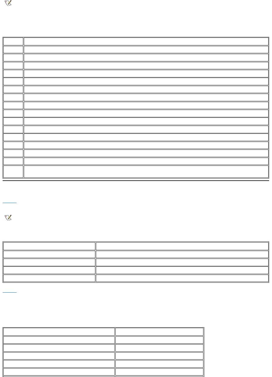
Table 3. IRQ Line Assignments
Memory Allocations
Table 4 provides a map of the conventional memory area. When the microprocessor or a program addresses a location within the conventional
memory range, it is physically addressing a location in main memory.
Table 4. Conventional Memory Map
Table 5 provides a map of the upper memory area. Some of these addresses are dedicated to various system devices, such as the system/video
basic input/output system (BIOS). Others are available for use by expansion cards and/or an expanded memory manager (EMM).
When the microprocessor or a program addresses a location within the upper memory area, it is physically addressing a location within one of
these devices.
Table 5. Upper Memory Map
NOTES: Installed devices cannot share the same COM port address. The default address of your computer's serial port is COM1.
To view IRQ line assignments in the Microsoft®Windows®95 and Windows 98 operating systems, click the Start button, point to
Settings, and click Control Panel. Double-click the System icon. Select the Device Manager tab, and then double-click Computer.
IRQ Line
Reserved/Available
IRQ0
Reserved; generated by the system timer
IRQ1
Reserved; generated by the keyboard controller to signal that the keyboard output buffer is full
IRQ2
Reserved; generated internally by the interrupt controller to enable IRQ8 through IRQ15
IRQ3
Available for use by a PC Card unless the integrated serial port or infrared port is configured for COM2 or COM4
IRQ4
Available for use by a PC Card unless the integrated serial port or infrared port is configured for COM1 (the default) or COM3
IRQ5
Available for use by the audio controller
IRQ6
Generated by the diskette drive controller to indicate that the diskette drive requires the attention of the microprocessor
IRQ7
Available for use by a PC Card or audio controller if the parallel port is disabled
IRQ8
Reserved; generated by the system I/O controller's RTC
IRQ9
Reserved
IRQ10
Available for use by a PC Card or audio controller unless the C/Port Family APR or C/Dock Family Expansion Station is attached
IRQ11
Available for use by USB, PC Card, video controller, and audio controller
IRQ12
Reserved; generated by the keyboard controller to indicate that the output buffer of the touch pad or external PS/2 mouse is full
IRQ13
Reserved; generated by the math coprocessor
IRQ14
Reserved; generated by the hard-disk drive to indicate that the drive requires the attention of the microprocessor
IRQ15
Reserved; generated by CD-ROM drive in the external media bay to indicate that the drive requires the attention of the
microprocessor
NOTE: To view memory allocations in Windows 95 and Windows 98, click the Start button, point to Settings, and click Control Panel.
Double-click the System icon. Click the Device Manager tab, and then double-click Computer.
Address Range
Use
0000h-003FFh
Interrupt vector table
00400h-004FFh
BIOS data area
00500h-005FFh
MS-DOS®and BASIC work area
00600h-9FBFFh
User memory
Address Range
Use
0009FC00-0009FFFF
PS/2-mouse data area
000A0000-000BFFFF
Video RAM
000C0000-000CBFFF
Video BIOS
000CC000-000CDFFF
PC Card
000F0000-000FFFFF
System BIOS
I/O Memory Map
Table 6 provides a map of memory addresses reserved by the computer for peripheral input/output (I/O) devices. Use the information in Table 6 to
determine if the memory address of an external device (such as a PC Card) conflicts with a memory address reserved by the computer.
Check the documentation of the external I/O device to determine its memory address. If a device's memory address conflicts with a memory
address reserved by the computer, change the address of the device.
Table 6. I/O Memory Map
Back to Contents Page
00100000-03FFFFFF
High memory area
FD000000-FDFFFFFF (approximate; not a fixed location)
Video RAM
FF200000-FF2FFFFF (approximate; not a fixed location)
Video RAM
FFFE0000-FFFFFFFF
BIOS ROM
NOTE: To view I/O addresses in Windows 95 and Windows 98, click the Start button,
point to Settings,andclickControl Panel. Double-click the System icon. Click the
Device Manager tab, and then double-click Computer.
Address
Device
0000-001F
DMA controller #1
0020-003F
Interrupt controller #1
0040-005F
System timers
0060-0060
Keyboard controller
0061-0061
System speaker
0064-0064
Keyboard controller
0070-007F
RTC and NMI enable
0080-009F
DMA page registers
00A0-00BF
Interrupt controller #2
00C0-00DF
DMA controller #2
00F0-00FF
Math coprocessor
0170-0177
CD-ROM drive controller
01F0-01F7
Hard-disk drive controller
0210-0217
Audio controller
0220-022F
Audio controller
0270-0277
Fast IR
0376-0376
IDE controller
0378-037F
LPT1
0388-038B
Audio controller
03B0-03BB
VGA
03C0-03DF
VGA
03E0-03E1
PC Card controller
03E8-03EF
Fast IR
03F2-03F5;
03F7-03F7
Diskette controller
03F8-03FF
COM1
0530-0537
Audio controller
0778-077B
ECP registers
ECE0-ECFF
USB controller
FFA0-FFAF
PCI-IDE bus registers

Оглавление
- Dell™Latitude™CS/CS
- AC Adapter: Dell™Latitude™CS/CS
- Power Management Settings: Dell™Latitude™CS/CS
- Batteries:Dell™Latitude™CS/CS
- CD-ROM and DVD-ROMDrives:Dell™Latitude™CS/CS
- ContactingDell:Dell™Latitude™CS/CS
- CustomizingYourComputer:Dell™Latitude™CS/CS
- Dell™Diagnostics:DellLatitude™CS/CS
- Diskette Drive: Dell™Latitude™CS/CS
- Display: Dell™Latitude™CS/CS
- Drivers:Dell™Latitude™CS/CS
- ErrorMessagesandFlashCodes:Dell™Latitude™CS/CS
- Connecting External Devices: Dell™Latitude™CS/CS
- GettingHelp:Dell™Latitude™CS/CS
- HelpOverview:Dell™Latitude™CSPortableComputersUser'sGuide
- Introduction:Dell™Latitude™CS/CS
- Keyboard: Dell™Latitude™CS/CS
- External Media Bay: Dell™Latitude™CS/CS
- MediaOptions:Dell™Latitude™CS/CS
- PC Cards: Dell™Latitude™CS/CS
- PoweringYourComputer:Dell™Latitude™CS/CS
- Preface:Dell™Latitude™CS/CS
- Removing and Replacing Parts: Dell™Latitude™CS/CS
- Suspend-to-Disk Utility: Dell™Latitude™CS/CS
- Securing Your Computer: Dell™Latitude™CS/CS
- Using the System Setup Program:Dell™Latitude™CS/CS
- SystemSetupOptions:Dell™Latitude™CS/CS
- TechnicalSpecifications:Dell™Latitude™CS/CS
- SetupandOperation:Dell™Latitude™CS/CS
- Touch Pad: Dell™Latitude™CS/CS
- TravelingWithYourComputer:Dell™Latitude™CS/CS
- TroubleshootingYourComputer:Dell™Latitude™CS/CS
- Installing the Microsoft® Windows® 95 and Windows 98 Operating System Drivers: Dell™Latitude™CS/CS
- Installing the Microsoft® Windows NT® Operating System Drivers: Dell™Latitude™ CS/CS
