Pioneer PLASMA DISPLAY: Option1 Settings Menu
Option1 Settings Menu: Pioneer PLASMA DISPLAY
Table of contents
- Precautions Important Information Warnings and Safety Precaution
- NOTE:
- Caution
- Contents
- How to use the safety metal fittings and the screws for safety metal fittings Ventilation Requirements for enclosure mounting Installation
- Creating a video wall Cable Management
- Caution on when the plasma monitor is installed vertically How to use the remote control
- Front View Part Names and Function
- Information Rear View/ Terminal Board
- Remote Control
- Basic Operations POWER VOLUME MUTING DISPLAY DIGITAL ZOOM AUTO SET UP OFF TIMER
- SCREEN SIZE Operation WIDE Operations
- SCREEN SIZE Operation with Computer Signals
- Menu Operations OSD (On Screen Display) Controls Setting the language for the menus
- Menu Tree
- Main menu
- Picture Settings Menu
- SOUND Settings Menu SCREEN Settings Menu
- Option1 Settings Menu
- Information
- Option2 Settings Menu
- ORBITER INVERSE
- SCREEN WIPER SOFT FOCUS
- Option3 Settings Menu
- PROGRAM TIMER
- Information
- DIVIDER DISP. MODE
- SCREEN ABL LINK
- REPEAT TIMER Advanced OSD Settings Menu Color System Settings Menu Source Information Menu
- mini D-Sub 15-pin connector (Analog) DVI-D 24-pin connector (Digital) Pin Assignments
- Table of Signals Supported Supported resolution
- Table of Signals Supported
- Troubleshooting
- Specifications
English
OSD (On Screen Display)
Controls
17
En
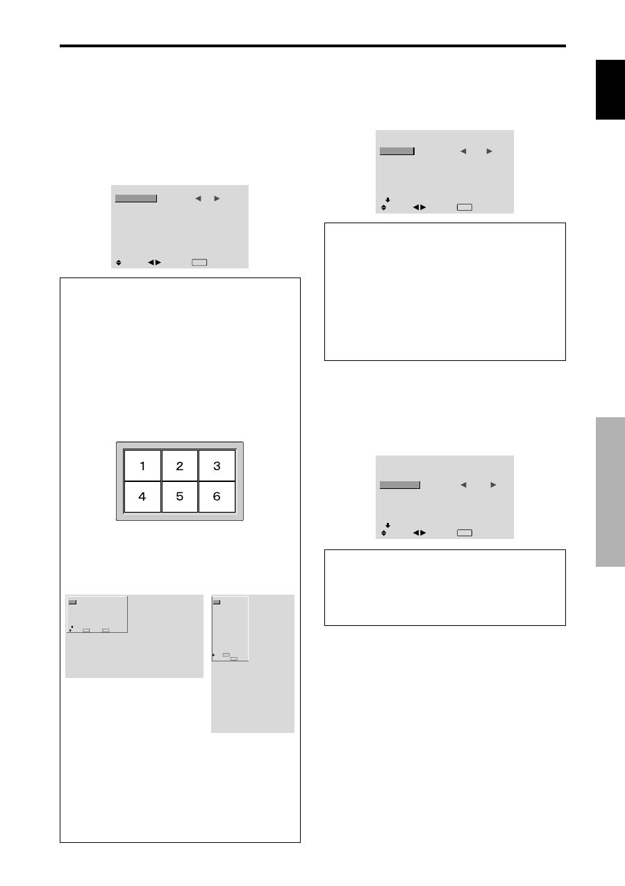
Option1 Settings Menu
Setting the on-screen display
This sets the position of the menu, the display format
(horizontal or vertical) etc.
Example: Turning the DISPLAY OSD off
On “OPTION1” menu, select “OSD”, then press the MENU/
SET button.
The “OSD” menu appears.
On “DISPLAY OSD” of “OSD” menu, select “OFF”.
OSD
DISPLAY OSD
OSD ADJUST
OSD ANGLE
OSD ORBITER
OSD CONTRAST
:
OFF
: 1
: H
: OFF
: LOW
SEL.
ADJ.
EXIT RETURN
Information
DISPLAY OSD settings
ON:
The informations on screen size, volume control,
etc. will be shown.
OFF:
The informations on screen size, volume control,
etc. will not be shown.
The DISPLAY button on the remote control will not
function either.
OSD ADJUST settings
Adjusts the position of the menu when it appears on
the screen.
The position can be set between 1 to 6.
OSD ANGLE settings
Sets the display format (landscape “H” or portrait “V”).
When the unit is installed vertically set the OSD
ANGLE at “V”.
“H”
“V”
OSD ORBITER settings
ON:
The position of the menu will be shifted by eight
dots each time OSD is displayed.
OFF:
OSD will be displayed at the same position.
OSD CONTRAST settings
NORMAL:
OSD brightness is set to normal.
LOW:
OSD brightness is set to lower.
Setting the PC2/COMPONENT2 connectors
Select whether to set the PC2/COMPONENT2 to RGB,
component or SCART1, 2.
Example: Set the BNC INPUT mode to “COMP.”
On “BNC INPUT” of “OPTION1” menu, select “COMP.”.
OPTION1
1 / 3
OSD
BNC INPUT
D-SUB INPUT
RGB SELECT
HD SELECT
INPUT SKIP
ALL RESET
NEXT PAGE
:
COMP.
: RGB
: AUTO
: 1080B
: OFF
: OFF
SEL.
ADJ.
EXIT RETURN
Information
BNC INPUT Settings
RGB:
Use the 5BNC terminals for HD, VD and RGB
signals.
COMP.:
Use the 3BNC terminals for component
signals.
SCART1:
Use the 4BNC terminals for RGB with
composite sync. See page 6.
SCART2:
Use the 3BNC terminals for RGB and the
VIDEO1 terminal for composite sync. See page 6.
OPTION1
1 / 3
OSD
BNC INPUT
D-SUB INPUT
RGB SELECT
HD SELECT
INPUT SKIP
ALL RESET
NEXT PAGE
: RGB
: RGB
: AUTO
: 1080B
: OFF
: OFF
SEL.
EXIT RETURN
OK
MENU
OPTION1
OSD
BNC INPUT
D-SUB INPUT
RGB SELECT
HD SELECT
INPUT SKIP
ALL RESET
: RGB
: RGB
: AUTO
: 1080B
: OFF
: OFF
1024
768
SEL.
EXIT RETURN
OK
MENU
Setting the PC1 connector
Select one of the signals being transmitted to the PC1
terminal.
Example: Set the D-SUB INPUT mode to “SCART3”
On “D-SUB INPUT” of “OPTION1” menu, select
“SCART3”.
OPTION1
1 / 3
OSD
BNC INPUT
D-SUB INPUT
RGB SELECT
HD SELECT
INPUT SKIP
ALL RESET
NEXT PAGE
: RGB
:
SCART3
: AUTO
: 1080B
: OFF
: OFF
SEL.
ADJ.
EXIT RETURN
Information
D-SUB INPUT Settings
RGB:
Use the D-SUB terminal for RGB signals.
SCART3:
Use the D-SUB terminal for RGB signal fed
from SCART. See page 6.
