Pioneer PLASMA DISPLAY: Information Rear View/ Terminal Board
Information Rear View/ Terminal Board: Pioneer PLASMA DISPLAY
Table of contents
- Precautions Important Information Warnings and Safety Precaution
- NOTE:
- Caution
- Contents
- How to use the safety metal fittings and the screws for safety metal fittings Ventilation Requirements for enclosure mounting Installation
- Creating a video wall Cable Management
- Caution on when the plasma monitor is installed vertically How to use the remote control
- Front View Part Names and Function
- Information Rear View/ Terminal Board
- Remote Control
- Basic Operations POWER VOLUME MUTING DISPLAY DIGITAL ZOOM AUTO SET UP OFF TIMER
- SCREEN SIZE Operation WIDE Operations
- SCREEN SIZE Operation with Computer Signals
- Menu Operations OSD (On Screen Display) Controls Setting the language for the menus
- Menu Tree
- Main menu
- Picture Settings Menu
- SOUND Settings Menu SCREEN Settings Menu
- Option1 Settings Menu
- Information
- Option2 Settings Menu
- ORBITER INVERSE
- SCREEN WIPER SOFT FOCUS
- Option3 Settings Menu
- PROGRAM TIMER
- Information
- DIVIDER DISP. MODE
- SCREEN ABL LINK
- REPEAT TIMER Advanced OSD Settings Menu Color System Settings Menu Source Information Menu
- mini D-Sub 15-pin connector (Analog) DVI-D 24-pin connector (Digital) Pin Assignments
- Table of Signals Supported Supported resolution
- Table of Signals Supported
- Troubleshooting
- Specifications
English
Part Names and Function
6
En
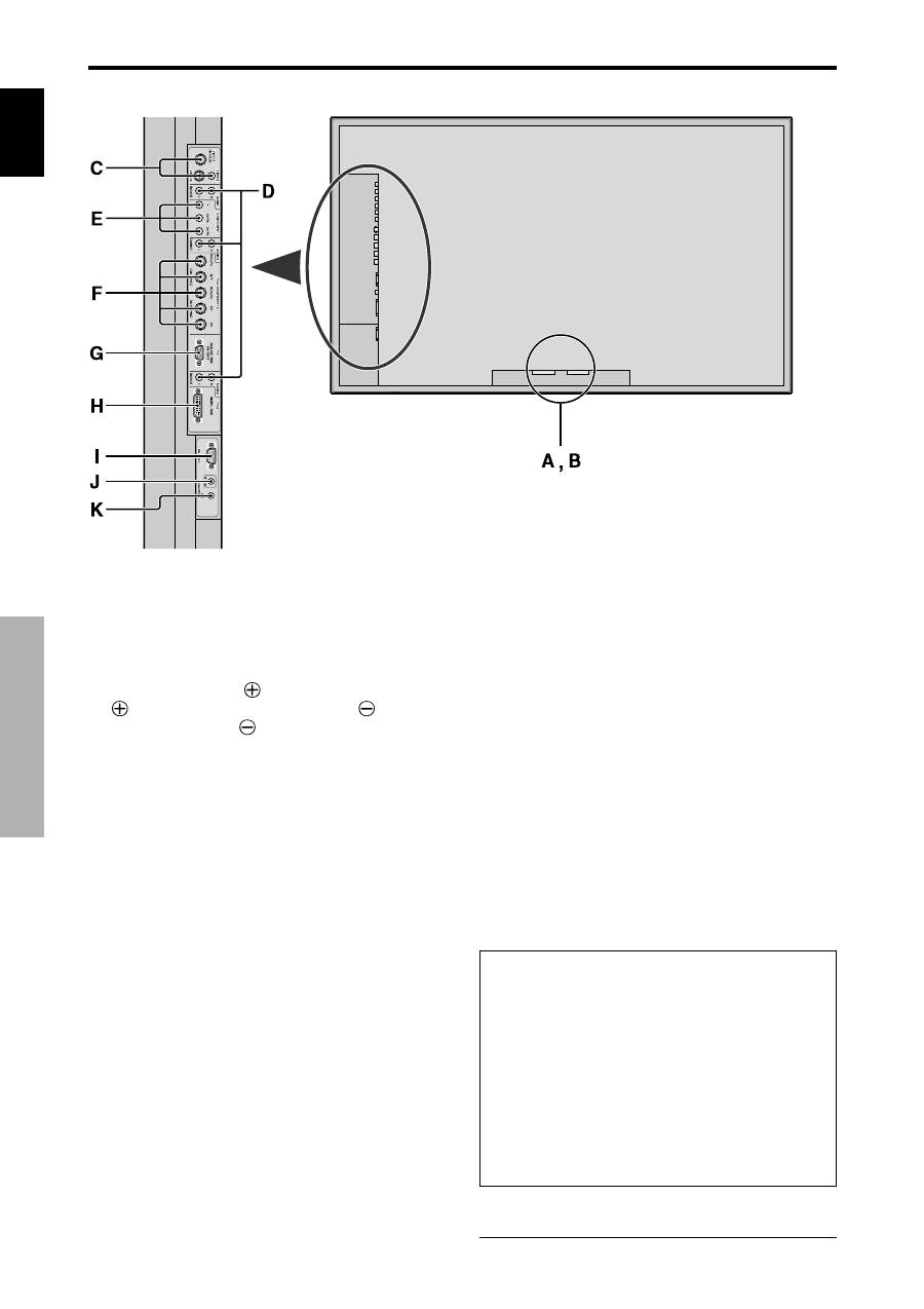
A
AC IN
Connect the included power cord here.
B
EXT SPEAKER L and R
Connect speakers (optional) here. Maintain the correct
polarity. Connect the
(positive) speaker wire to the
EXT SPEAKER terminal and the
(negative)
speaker wire to the
EXT SPEAKER terminal on
both LEFT and RIGHT channels.
Please refer to your speaker’s owner’s manual.
C
VIDEO1, 2, 3 (BNC, RCA, S-Video)
Connect VCR’s, DVD’s or Video Cameras, etc. here.
VIDEO1 can be used for Input or Output (see page
24).
D
AUDIO1, AUDIO2, AUDIO3
These are audio input terminals.
The input is selectable. Set which video image to allot
them from the SOUND menu screen.
E
COMPONENT1
Connect DVD’s, High Definition or Laser Discs, etc.
here.
F
PC2/COMPONENT2
PC2:
You can connect an analog RGB signal
and the syncronization signal.
COMPONENT2: You can connect DVDs, High
Definition sources, Laser Discs, etc.
here.
This input can be set for use with an
RGB or component source (see page
17).
G
PC1 (mini D-Sub 15pin)
Connect an analog RGB signal from a computer, etc.
here. This input can be used for Input or Output (see
page 24).
H
PC3
(DVI 24pin)
Connect a digital signal (TMDS) from a source with a
DVI output.
I
RS-232C
Never connect any component to this connector
without first consulting your Pioneer installation
technician.
This connector is used for plasma display setup
adjustments.
J
REMOTE IN
Connect the remote cable* to the remote control’s
remote jack to obtain wired remote control.
K
REMOTE OUT
Connect the remote cable* to the REMOTE IN jack of
the other display monitor to obtain wired remote
control.
Information
• For Y/CB/Cr, connect to the COMPONENT1 or PC2/
COMPONENT2 terminals.
• For SCART, this unit provides three ways to connect:
·
SCART1:
Connect R/G/B and composite sync. to
the PC2/COMPONENT2 terminals. (R, G, B and
HD connector)
·
SCART2:
Connect R/G/B to the COMPONENT2
terminals and composite sync. to the VIDEO1
terminal.
·
SCART3:
Connect R/G/B and composite sync. to
the PC1 terminal.
* The 1/8 Stereo Mini cable must be purchased separately.
Rear View/ Terminal Board
