Pioneer PLASMA DISPLAY – page 2
Manual for Pioneer PLASMA DISPLAY
Table of contents
- Precautions Important Information Warnings and Safety Precaution
- NOTE:
- Caution
- Contents
- How to use the safety metal fittings and the screws for safety metal fittings Ventilation Requirements for enclosure mounting Installation
- Creating a video wall Cable Management
- Caution on when the plasma monitor is installed vertically How to use the remote control
- Front View Part Names and Function
- Information Rear View/ Terminal Board
- Remote Control
- Basic Operations POWER VOLUME MUTING DISPLAY DIGITAL ZOOM AUTO SET UP OFF TIMER
- SCREEN SIZE Operation WIDE Operations
- SCREEN SIZE Operation with Computer Signals
- Menu Operations OSD (On Screen Display) Controls Setting the language for the menus
- Menu Tree
- Main menu
- Picture Settings Menu
- SOUND Settings Menu SCREEN Settings Menu
- Option1 Settings Menu
- Information
- Option2 Settings Menu
- ORBITER INVERSE
- SCREEN WIPER SOFT FOCUS
- Option3 Settings Menu
- PROGRAM TIMER
- Information
- DIVIDER DISP. MODE
- SCREEN ABL LINK
- REPEAT TIMER Advanced OSD Settings Menu Color System Settings Menu Source Information Menu
- mini D-Sub 15-pin connector (Analog) DVI-D 24-pin connector (Digital) Pin Assignments
- Table of Signals Supported Supported resolution
- Table of Signals Supported
- Troubleshooting
- Specifications
English
OSD (On Screen Display) Controls
16
En
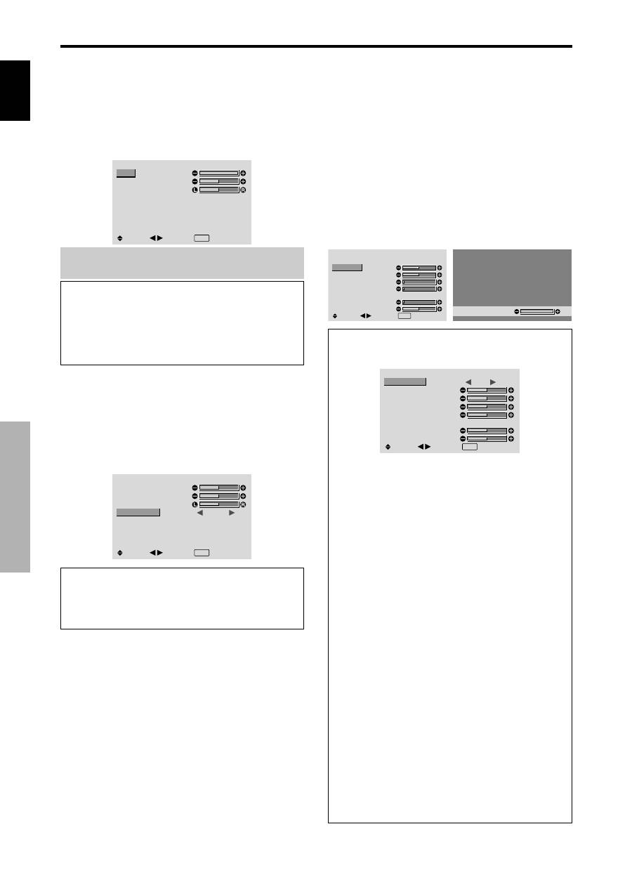
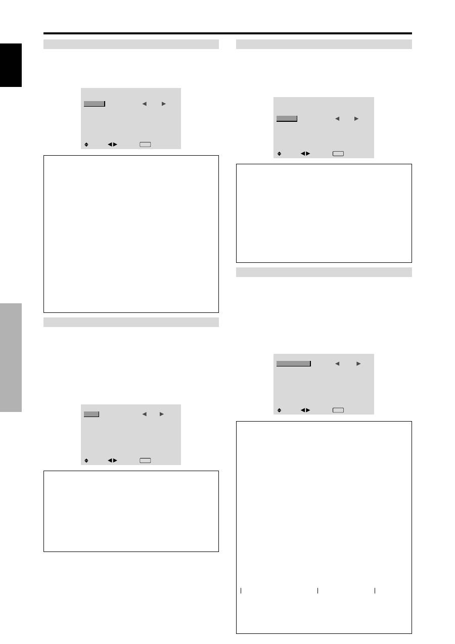
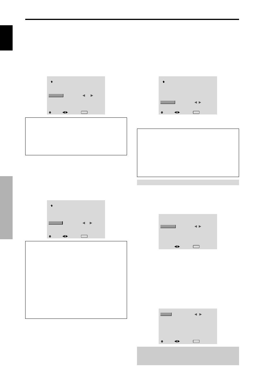
SOUND Settings Menu
Adjusting the treble, bass and left/right
balance and audio input select
The treble, bass and left/right balance can be adjusted to
suit your tastes.
Example: Adjusting the bass
On “BASS” of “SOUND” menu, adjust the bass.
SOUND
BASS
TREBLE
BALANCE
AUDIO INPUT1
AUDIO INPUT2
AUDIO INPUT3
: VIDEO1
: COMPNT1
: PC1DSUB
SEL.
ADJ.
EXIT RETURN
Note :
If “CAN NOT ADJUST” appears...
Set “AUDIO INPUT” on the SOUND menu correctly.
Information
SOUND settings menu
BASS:
Controls the level of low frequency sound.
TREBLE:
Controls the level of high frequency sound.
BALANCE:
Controls the balance of the left and right
channels.
Setting the allocation of the audio connectors
Setting the AUDIO 1, 2, and 3 connectors to the desired
input.
Example: Setting “AUDIO INPUT1” to “VIDEO 2”
On “AUDIO INPUT1” of “SOUND” menu, select
“VIDEO2”.
The available sources depend on the settings of input.
SOUND
BASS
TREBLE
BALANCE
AUDIO INPUT1
AUDIO INPUT2
AUDIO INPUT3
:
VIDEO2
: COMPNT1
: PC1DSUB
SEL.
ADJ.
EXIT RETURN
Information
AUDIO INPUT
A single audio input cannot be selected as the audio
channel for more than one input terminal.
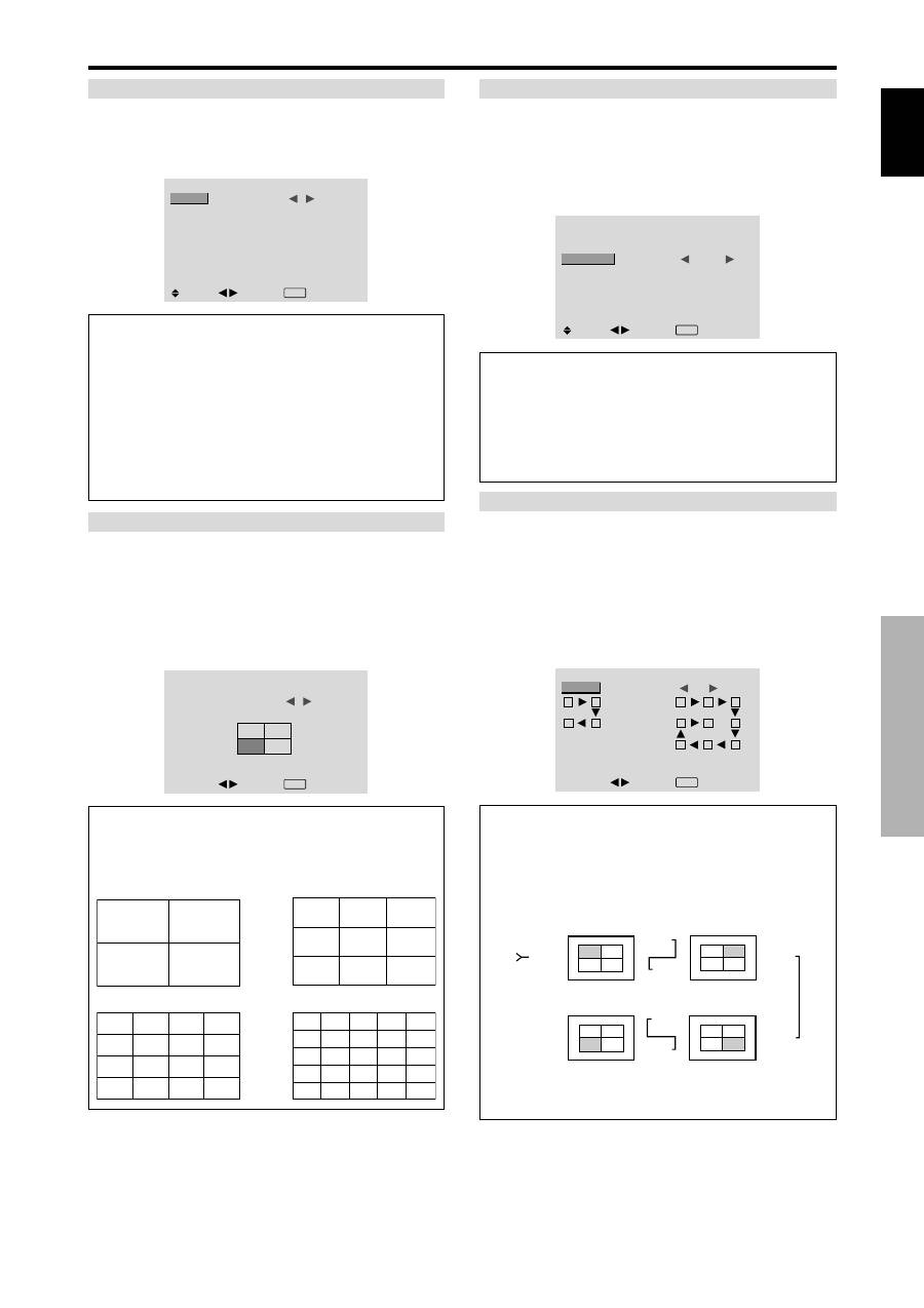
SCREEN Settings Menu
Adjusting the Position, Size, PHASE, CLOCK
The position of the image can be adjusted and flickering
of the image can be corrected.
Example: Adjusting the vertical position in the normal
mode
On “V.POSITION” of “SCREEN” menu, adjust the position.
The mode switches as follows each time the
or
button is
pressed:
4:3
↔
FULL
* The mode can also be switched by pressing the SCREEN
SIZE button on the remote control.
* The settings on the SCREEN menu are not preset at the
factory.
SCREEN
SCREEN SIZE
V. POSITION
H. POSITION
V. SIZE
H. SIZE
AUTO PICTURE
PHASE
CLOCK
: 4 : 3
: OFF
SEL.
ADJ.
EXIT RETURN
V.POSITION
+ 6 4
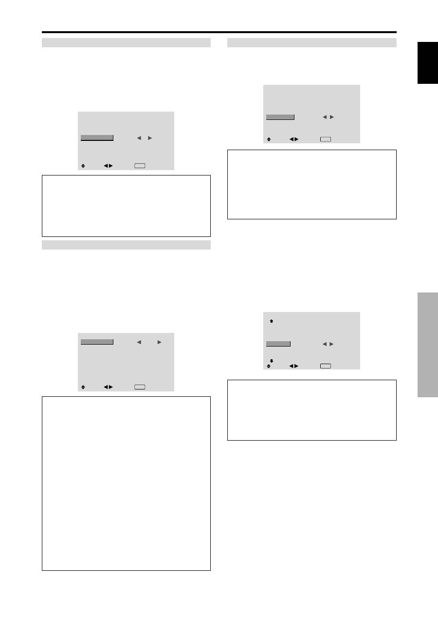
Information
When “AUTO PICTURE” is “OFF”
SCREEN
SCREEN SIZE
V. POSITION
H. POSITION
V. SIZE
H. SIZE
AUTO PICTURE
PHASE
CLOCK
:
FULL
: OFF
SEL.
ADJ.
EXIT RETURN
When Auto Picture is off, the PHASE and the CLOCK
items are displayed so that you can adjust them.
Adjusting the Auto Picture
ON:
The CLOCK, PHASE and Position adjustments
are made automatically.
Not available for digital ZOOM.
OFF:
The CLOCK, PHASE and Position adjustments
are made manually.
* If PHASE can’t be adjusted, set Auto Picture to OFF
and adjust manually.
Adjusting the position of the image
V.POSITION:
Adjusts the vertical position of the
image.
H.POSITION:
Adjusts the horizontal position of the
image.
V.SIZE:
Adjusts the vertical size of the image. (Except
for WIDE mode)
H.SIZE:
Adjusts the horizontal size of the image.
(Except for WIDE mode)
PHASE
*
:
Adjusts for flickering.
CLOCK
*
:
Adjusts for striped patterns on the image.
* The CLOCK and PHASE features are available only
when the “Auto Picture” is off.
* The AUTO PICTURE, PHASE and CLOCK are
available only for RGB signals.
But, these features are not available for moving pictures
on RGB, VIDEO or COMPONENT.
English
OSD (On Screen Display)
Controls
17
En
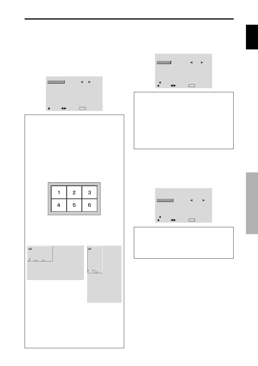
Option1 Settings Menu
Setting the on-screen display
This sets the position of the menu, the display format
(horizontal or vertical) etc.
Example: Turning the DISPLAY OSD off
On “OPTION1” menu, select “OSD”, then press the MENU/
SET button.
The “OSD” menu appears.
On “DISPLAY OSD” of “OSD” menu, select “OFF”.
OSD
DISPLAY OSD
OSD ADJUST
OSD ANGLE
OSD ORBITER
OSD CONTRAST
:
OFF
: 1
: H
: OFF
: LOW
SEL.
ADJ.
EXIT RETURN
Information
DISPLAY OSD settings
ON:
The informations on screen size, volume control,
etc. will be shown.
OFF:
The informations on screen size, volume control,
etc. will not be shown.
The DISPLAY button on the remote control will not
function either.
OSD ADJUST settings
Adjusts the position of the menu when it appears on
the screen.
The position can be set between 1 to 6.
OSD ANGLE settings
Sets the display format (landscape “H” or portrait “V”).
When the unit is installed vertically set the OSD
ANGLE at “V”.
“H”
“V”
OSD ORBITER settings
ON:
The position of the menu will be shifted by eight
dots each time OSD is displayed.
OFF:
OSD will be displayed at the same position.
OSD CONTRAST settings
NORMAL:
OSD brightness is set to normal.
LOW:
OSD brightness is set to lower.
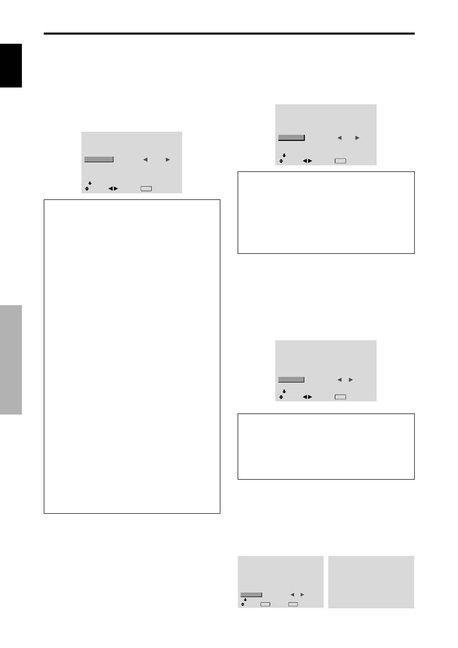
Setting the PC2/COMPONENT2 connectors
Select whether to set the PC2/COMPONENT2 to RGB,
component or SCART1, 2.
Example: Set the BNC INPUT mode to “COMP.”
On “BNC INPUT” of “OPTION1” menu, select “COMP.”.
OPTION1
1 / 3
OSD
BNC INPUT
D-SUB INPUT
RGB SELECT
HD SELECT
INPUT SKIP
ALL RESET
NEXT PAGE
:
COMP.
: RGB
: AUTO
: 1080B
: OFF
: OFF
SEL.
ADJ.
EXIT RETURN
Information
BNC INPUT Settings
RGB:
Use the 5BNC terminals for HD, VD and RGB
signals.
COMP.:
Use the 3BNC terminals for component
signals.
SCART1:
Use the 4BNC terminals for RGB with
composite sync. See page 6.
SCART2:
Use the 3BNC terminals for RGB and the
VIDEO1 terminal for composite sync. See page 6.
OPTION1
1 / 3
OSD
BNC INPUT
D-SUB INPUT
RGB SELECT
HD SELECT
INPUT SKIP
ALL RESET
NEXT PAGE
: RGB
: RGB
: AUTO
: 1080B
: OFF
: OFF
SEL.
EXIT RETURN
OK
MENU
OPTION1
OSD
BNC INPUT
D-SUB INPUT
RGB SELECT
HD SELECT
INPUT SKIP
ALL RESET
: RGB
: RGB
: AUTO
: 1080B
: OFF
: OFF
1024
768
SEL.
EXIT RETURN
OK
MENU
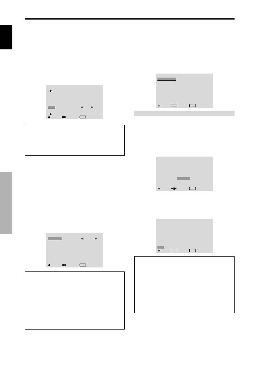
Setting the PC1 connector
Select one of the signals being transmitted to the PC1
terminal.
Example: Set the D-SUB INPUT mode to “SCART3”
On “D-SUB INPUT” of “OPTION1” menu, select
“SCART3”.
OPTION1
1 / 3
OSD
BNC INPUT
D-SUB INPUT
RGB SELECT
HD SELECT
INPUT SKIP
ALL RESET
NEXT PAGE
: RGB
:
SCART3
: AUTO
: 1080B
: OFF
: OFF
SEL.
ADJ.
EXIT RETURN
Information
D-SUB INPUT Settings
RGB:
Use the D-SUB terminal for RGB signals.
SCART3:
Use the D-SUB terminal for RGB signal fed
from SCART. See page 6.
English
OSD (On Screen Display) Controls
18
En
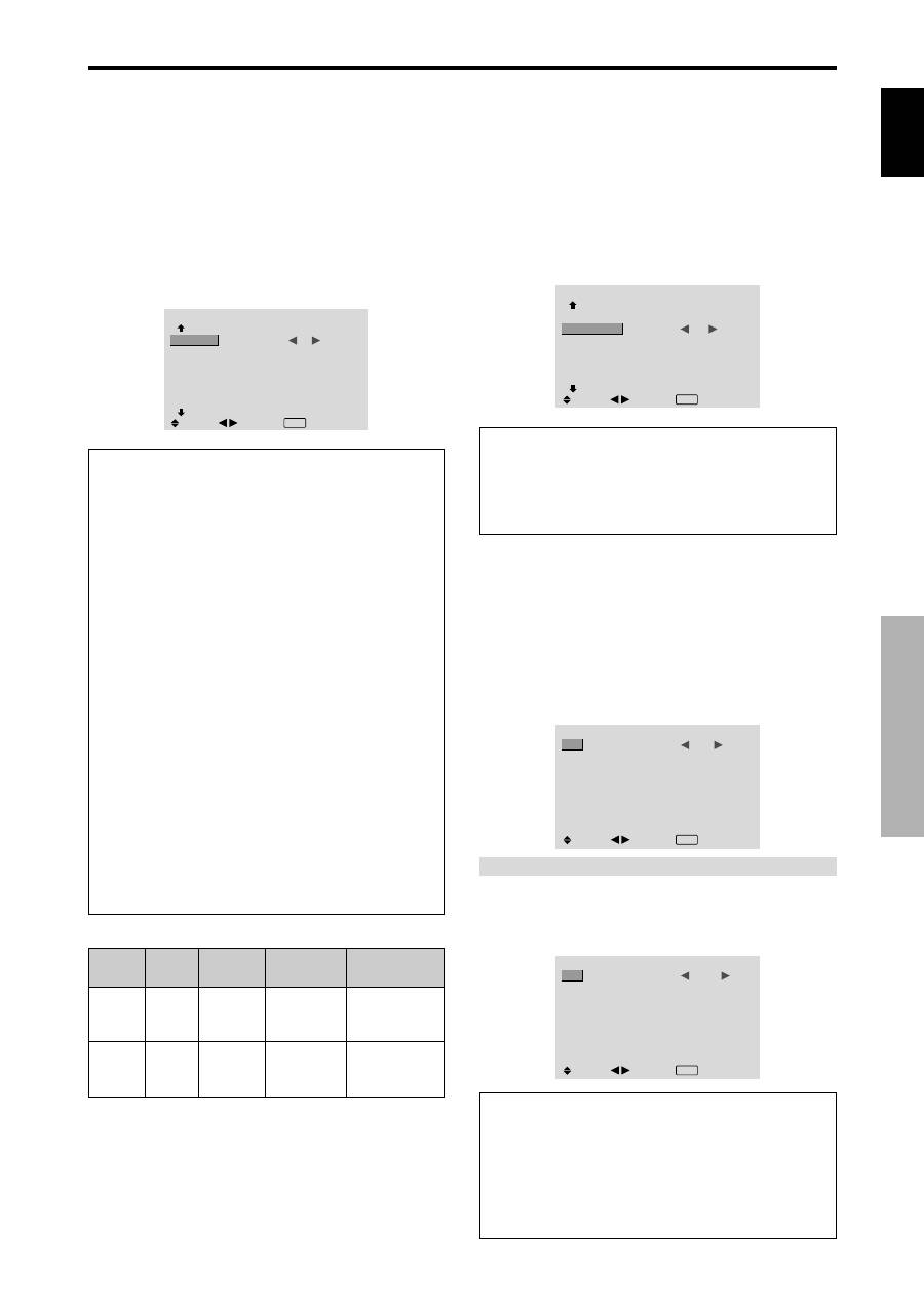
Setting high definition images to the suitable
screen size
Use this procedure to set whether the number of vertical
lines of the input high definition image is 1035 or 1080.
Example: Setting the “HD SELECT” mode to “1035I”
On “HD SELECT” of “OPTION1” menu, select “1035I”.
OPTION1
1 / 3
OSD
BNC INPUT
D-SUB INPUT
RGB SELECT
HD SELECT
INPUT SKIP
ALL RESET
NEXT PAGE
: RGB
: RGB
: AUTO
:
1035
I
: OFF
: OFF
SEL.
ADJ.
EXIT RETURN
Information
HD SELECT modes
These 3 modes are not displayed in correct image
automatically.
1080B:
Standard digital broadcasts
1035I:
Japanese “High Vision” signal format
1080A:
Special Digital broadcasts (for example :
DTC100)
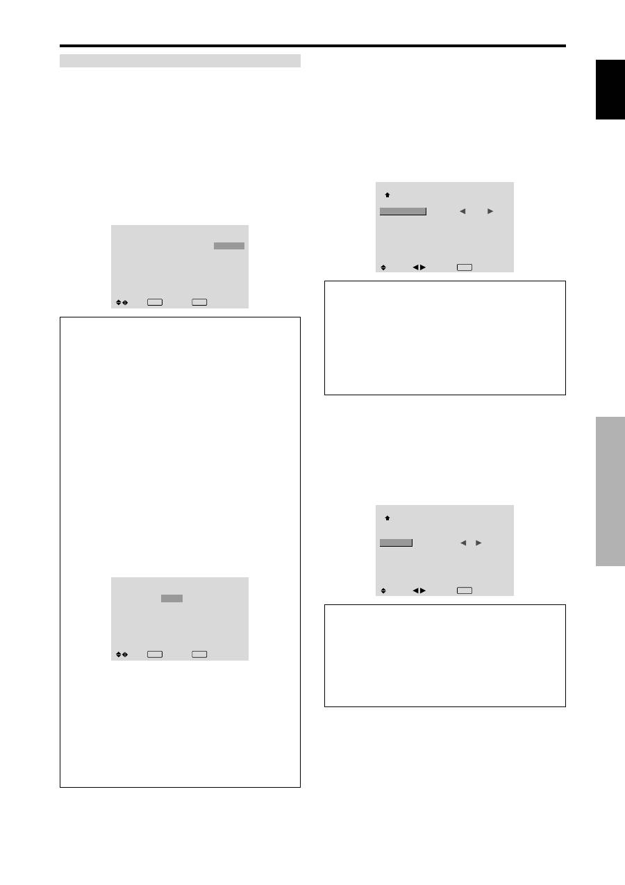
Setting the Input Skip
When this is ON, signals which are not present will be
skipped over and only pictures whose signals are being
transmitted will be displayed.
This setting is valid only for the INPUT/EXIT button on
the unit.
Example: Set to “ON”
On “INPUT SKIP” of “OPTION1” menu, select “ON”.
OPTION1
1 / 3
OSD
BNC INPUT
D-SUB INPUT
RGB SELECT
HD SELECT
INPUT SKIP
ALL RESET
NEXT PAGE
: RGB
: RGB
: AUTO
: 1080B
:
ON
: OFF
SEL.
ADJ.
EXIT RETURN
Resetting to the default values
Use these operations to restore all the settings (PICTURE,
SOUND, SCREEN, OPTION1~3, etc) to the factory
default values.
Refer to page 12 for items to be reset.
On “ALL RESET” of “OPTION1” menu, select “ON”, then
press the MENU/SET button.
OPTION1
1 / 3
OSD
BNC INPUT
D-SUB INPUT
RGB SELECT
HD SELECT
INPUT SKIP
ALL RESET
NEXT PAGE
: RGB
: RGB
: AUTO
: 1080B
: OFF
:
ON
SEL.
EXIT RETURN
OK
MENU
ALL RESET
SETTING NOW
When the “SETTING NOW” screen disappears, then all the
settings are restored to the default values.
Information
INPUT SKIP settings
OFF:
Regardless of the presence of the signal, scan
and display all signals.
ON:
If no input signal is present, skip that signal.
* “SETTING NOW” will appear during the input search.
Setting a computer image to the correct RGB
select screen
With the computer image, select the RGB Select mode
for a moving image such as (video) mode, wide mode or
digital broadcast.
Example: Setting the “RGB SELECT” mode to
“MOTION ”
On “RGB SELECT” of “OPTION1” menu, select
“MOTION”.
OPTION1
1 / 3
OSD
BNC INPUT
D-SUB INPUT
RGB SELECT
HD SELECT
INPUT SKIP
ALL RESET
NEXT PAGE
: RGB
: RGB
:
MOTION
1024
×
768
: OFF
: OFF
SEL.
ADJ.
EXIT RETURN
Information
RGB SELECT modes
One of these 8 modes must be selected in order to
display the following signals correctly.
AUTO:
Select the suitable mode for the specifications
of input signals as listed in the table “Computer input
signals supported by this system” on page 29.
STILL:
To display VESA standard signals. (Use this
mode for a still image from a computer.)
MOTION:
The video signal (from a scan converter)
will be converted to RGB signals to make the picture
more easily viewable. (Use this mode for a motion
image from a computer.)
WIDE1:
When an 852 dot
480 line signal with a
horizontal frequency of 31.7kHz is input, the image may
be compressed horizontally. To prevent this, set RGB
SELECT to WIDE1.
WIDE2:
When an 848 dot
480 line signal with a
horizontal frequency of 31.0 kHz is input, the image
may be compressed horizontally. To prevent this, set
RGB SELECT to WIDE2.
WIDE3:
When an 1920 dot
1200 line signal with a
horizontal frequency of 74.0 kHz is input, the image
may be compressed horizontally. To prevent this, set
RGB SELECT to WIDE3.
WIDE4:
When an 1280 dot
768 line signal with a
horizontal frequency of 59.8 kHz or an 1680 dot
1050
line signal with a horizontal frequency of 60 kHz is
input, the image may be compressed horizontally. To
prevent this, set RGB SELECT to WIDE4.
DTV:
Set this mode when watching digital broadcasting
(480P).
See page 29 for the details of the above settings.
English
OSD (On Screen Display) Controls
19
En
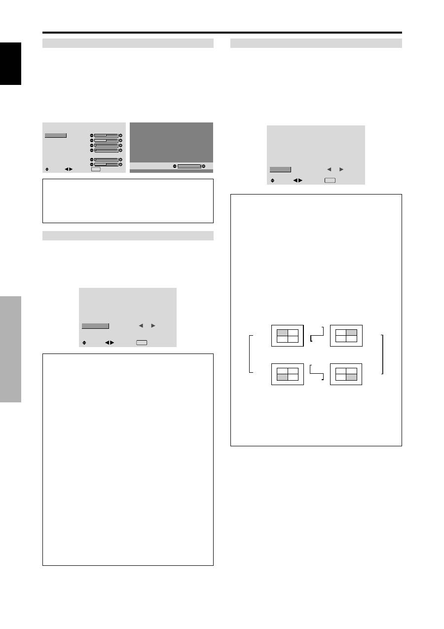
Option2 Settings Menu
Setting the power management for computer
images
This energy-saving (power management) function
automatically reduces the monitor’s power consumption
if no operation is performed for a certain amount of time.
Example: Turning the power management function on
Set “ADVANCED OSD” to “ON” in the main menu (1/
2), then perform the following operations.
On “PWR. MGT.” of “OPTION2” menu, select “ON”.
OPTION2
2 / 3
PREVIOUS PAGE
PWR. MGT.
PURECINEMA
LONG LIFE
SIDE MASK
S1/S2
DVI SET-UP
NEXT PAGE
:
ON
: ON
: 3
: OFF
SEL.
ADJ.
EXIT RETURN
Information
Power management function
* The power management function automatically reduces
the monitor’s power consumption if the computer’s
keyboard or mouse is not operated for a certain amount
of time. This function can be used when using the
monitor with a computer.
* If the computer’s power is not turned on or if the
computer and selector tuner are not properly connected,
the system is set to the off state.
* For instructions on using the computer’s power
management function, refer to the computer’s operating
instructions.
Power management settings
ON:
In this mode the power management function is
turned on.
OFF:
In this mode the power management function is
turned off.
Power management function and STANDBY/
ON indicator
The STANDBY/ON indicator indicates the status of
the power management function. See below for
indicator status and description.
STANDBY/ON indicator
Power
management
mode
On
Off
Turning the picture
back on
Picture already on.
Operate the keyboard or
mouse. The picture
reappears.
STANDBY/
ON indicator
Green
Red
Power
management
operating status
Not activated.
Activated.
Description
Horizontal and vertical
synchronizing signals
are present from the
computer.
Horizontal and/or
vertical synchronizing
signals are not sent
from the computer.
Setting the picture to suit the movie
The film image is automatically discriminated and
projected in an image mode suited to the picture.
[NTSC, PAL, PAL60, 480I (60Hz), 525I (60Hz), 576I
(50Hz), 625I (50Hz), 1035I (60Hz), 1080I (60Hz) only]
Example: Setting the “PURECINEMA” to “OFF”
Set “ADVANCED OSD” to “ON” in the main menu (1/
2), then perform the following operations.
On “PURECINEMA” of “OPTION2” menu, select “OFF”.
OPTION2
2 / 3
: OFF
:
OFF
: 3
: OFF
SEL.
ADJ.
PREVIOUS PAGE
PWR. MGT.
PURECINEMA
LONG LIFE
SIDE MASK
S1/S2
DVI SET-UP
NEXT PAGE
EXIT RETURN
Information
PURECINEMA
ON:
Automatic discrimination of the image and
projection in PURECINEMA.
OFF:
PURECINEMA does not function.
Reducing burn-in of the screen
The brightness of the screen, the position of the picture,
positive/negative mode and screen wiper are adjusted to
reduce burn-in of the screen.
Set “ADVANCED OSD” to “ON” in the main menu (1/
2), then perform the following operations.
On “OPTION2” menu, select “LONG LIFE”, then press the
MENU/SET button.
The “LONG LIFE” screen appears.
LONG LIFE
ABL
ORBITER
INVERSE
SCREEN WIPER
SOFT FOCUS
:
AUTO
: OFF
: OFF
: OFF
: OFF
SEL.
ADJ.
EXIT RETURN
ABL (Auto Brightness Limiter)
Use this to activate the brightness limiter.
Example: Setting “ABL” to “LOCK1”
On “ABL” of “LONG LIFE” menu, select “LOCK1”.
LONG LIFE
ABL
ORBITER
INVERSE
SCREEN WIPER
SOFT FOCUS
:
LOCK1
: OFF
: OFF
: OFF
: OFF
SEL.
ADJ.
EXIT RETURN
Information
ABL settings
AUTO:
The brightness of the screen is adjusted
automatically to suit the picture quality.
LOCK1, 2, 3:
Sets maximum brightness.
The brightness level decreases in the order of LOCK 1,
2, 3. LOCK 3 provides minimum brightness.
English
OSD (On Screen Display) Controls
20
En
ORBITER
Use this to set the picture shift.
Example: Setting “ORBITER” to “AUTO1”
On “ORBITER” of “LONG LIFE” menu, select “AUTO1”.
LONG LIFE
ABL
ORBITER
INVERSE
SCREEN WIPER
SOFT FOCUS
: AUTO
:
AUTO1
: OFF
: OFF
: OFF
SEL.
ADJ.
EXIT RETURN
Information
ORBITER settings
OFF:
Orbiter mode does not function.
This is the default setting when PC signal is input.
AUTO1:
The picture moves around the screen
intermittently, making the picture smaller. This is the
default setting when a Video or a COMPONENT signal
is input. Set to “OFF” when these signals are not used.
AUTO2:
The picture moves around the screen
intermittently, making the picture bigger.
MANUAL:
User can adjust the orbiter function
(Horizontal Dot, Vertical Line and Time) manually.
See the following explanation.
* When a Video or a COMPONENT signal is input, the
AUTO1 and 2 functions will affect only the moving
picture and will not make the screen smaller or bigger.
Adjust the ORBITER function manually
Set the amount of shift and the time between movement.
Example: Setting so that the picture moves 2 dots
horizontally and 4 lines vertically every 3 minutes.
On “ORBITER” of “LONG LIFE” menu, select
“MANUAL”, then press the MENU/SET button.
THE “ORBITER” screen appears.
Adjust the items.
ORBITER
H-DOT
V-LINE
TIME
:
2 DOT
: 4 LINE
: 3 M
SEL.
ADJ.
EXIT RETURN
Information
ORBITER Function settings
H-DOT:
Moves from 1 to 20 dots in the horizontal
direction.
V-LINE:
Moves from 1 to 20 lines in the vertical
direction.
TIME:
Interval of 1~5 minutes (1 horizontal dot or 1
vertical line per interval).
INVERSE
Use this to set the inverse mode or to display a white
screen.
Example: Setting “INVERSE” to “WHITE”
On “INVERSE” of “LONG LIFE” menu, select “WHITE”.
LONG LIFE
ABL
ORBITER
INVERSE
SCREEN WIPER
SOFT FOCUS
: AUTO
: OFF
:
WHITE
: OFF
: OFF
SEL.
ADJ.
EXIT RETURN
Information
INVERSE Settings
ON:
The picture is displayed alternately between
positive image and negative image.
You can set the time by pressing the MENU/SET button
while “ON” is set.
OFF:
Inverse mode does not function.
WHITE:
The entire screen turns white.
You can set the time by pressing the MENU/SET button
while “ON” is set.
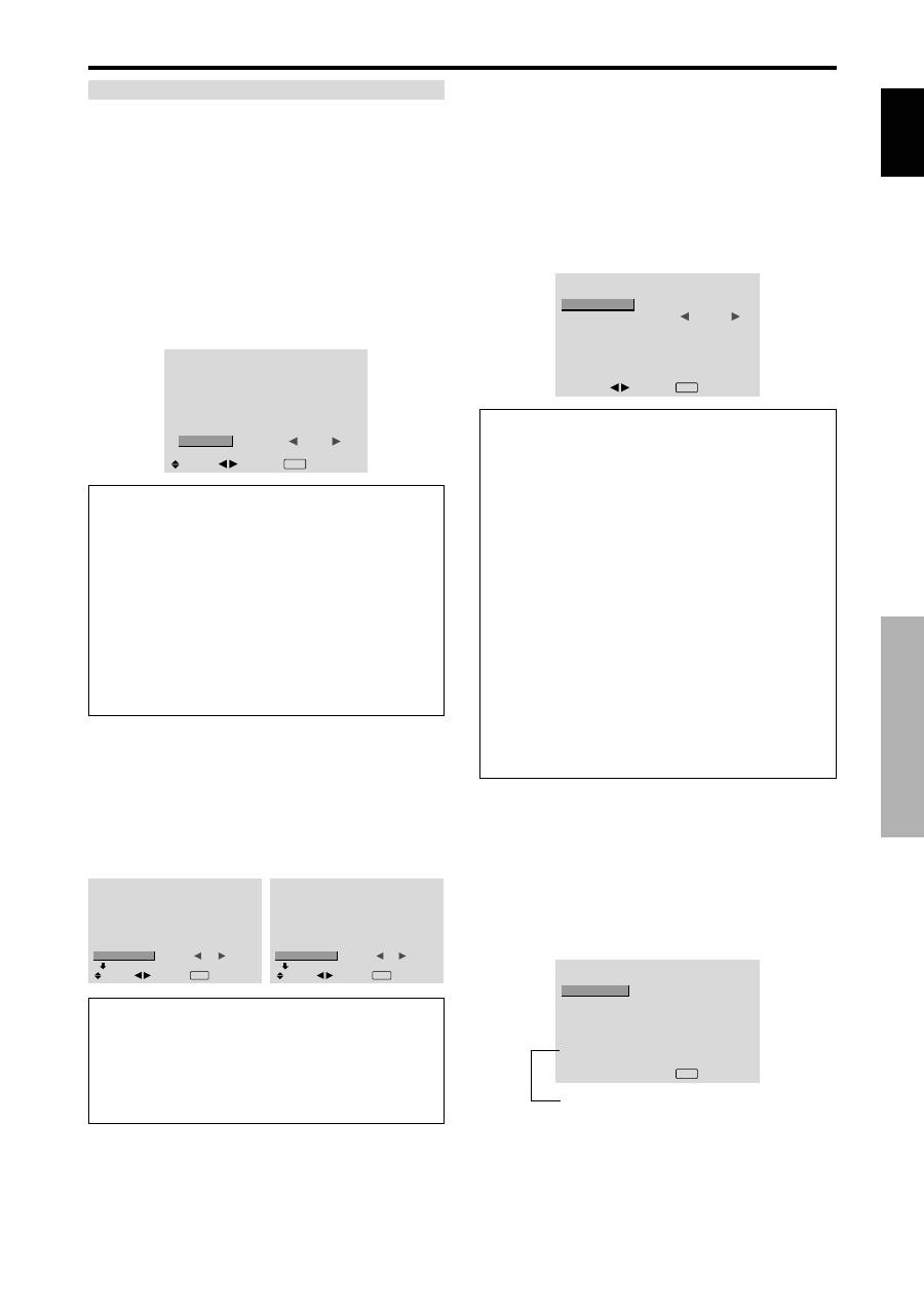
Setting the time for INVERSE/WHITE
Set a time duration.
Example: Setting to that the INVERSE mode starts
in 2 hours and proceeds for one hour and a half.
On “INVERSE” of “LONG LIFE” menu, select “ON”, then
press the MENU/SET button.
THE “INVERSE/WHITE” screen appears.
Adjust the times.
INVERSE/WHITE
WORKING TIME
WAITING TIME
:
01H30M
: 02H00M
SEL.
ADJ.
EXIT RETURN
Information
Setting the time
WORKING TIME:
Set the time duration for
“INVERSE/WHITE”.
When the WORKING TIME is set to “ON” the mode
will stay on.
WAITING TIME:
Set the standby time until the
“INVERSE/WHITE” mode starts.
* The “WAITING TIME” can not be set when the
“WORKING TIME” is ON.
* THE “WORKING TIME” and “WAITING TIME” can be
set for up to 12 hours and 45 minutes in units of 3 minutes.
* Ending a WORKING TIME function, the monitor will
be STAND BY.
[Example]
WORKING TIME: 01H30M
WAITING TIME: 02H00M
To select “ON” for the “WORKING TIME”...
Set the hours of the working time to 0H and the minutes
to 0M. “ON” will be displayed.
←−−−−
2 H
−−−−→←−−
1.5 H
−−→←−−−−
Start
INVERSE/WHITE Start
STAND BY
English
OSD (On Screen Display) Controls
21
En
SCREEN WIPER
When this is set to ON, a white vertical bar moves
repeatedly from the left and of the screen to the right end
at a constant speed.
Example: Setting “SCREEN WIPER” to “ON”
On “SCREEN WIPER” of “LONG LIFE” menu, select
“ON”.
LONG LIFE
ABL
ORBITER
INVERSE
SCREEN WIPER
SOFT FOCUS
: AUTO
: OFF
: OFF
:
ON
: OFF
SEL.
ADJ.
EXIT RETURN
Information
SCREEN WIPER
ON:
The white vertical bar appears.
You can set the time by pressing the MENU/SET button
while “ON” is set.
OFF:
Screen wiper mode does not function.
Setting the time for SCREEN WIPER
Set a time duration and the speed.
Example: Setting so that the SCREEN WIPER mode
starts in 30 minutes and proceeds for one and a half
hours.
On “SCREEN WIPER” of “LONG LIFE” menu, select
“ON”, then press the MENU/SET button.
THE “SCREEN WIPER” screen appears.
Adjust the times and speed.
SCREEN WIPER
WORKING TIME
WAITING TIME
SPEED
:
01H30M
: 00H30M
: 3
SEL.
ADJ.
EXIT RETURN
Information
Setting the time
WORKING TIME:
Set the time duration for “SCREEN
WIPER”.
When the WORKING TIME is set to “ON” the mode
will stay on.
WAITING TIME:
Set the standby time until the
“SCREEN WIPER” mode starts.
SPEED:
Set the moving speed for the “SCREEN
WIPER”. The speed decreases as the number increases.
* The “WAITING TIME” can not be set when the
“WORKING TIME” is ON.
* THE “WORKING TIME” and “WAITING TIME” can
be set for up to 12 hours and 45 minutes in units of 3
minutes.
To select “ON” for the “WORKING TIME”...
Set the hours of the working time to 0H and the minutes
to 0M. “ON” will be displayed.
SOFT FOCUS
Reduces edges and softens the image.
Example: Setting “SOFT FOCUS” to “2”
On “SOFT FOCUS” of “LONG LIFE” menu, select “2”.
LONG LIFE
ABL
ORBITER
INVERSE
SCREEN WIPER
SOFT FOCUS
: AUTO
: OFF
: OFF
: OFF
:
2
SEL.
ADJ.
EXIT RETURN
Information
SOFT FOCUS settings
OFF:
Turns the SOFT FOCUS function off.
1, 2, 3, 4:
Activates the SOFT FOCUS setting. The
higher numbers create a softer image.
“SHARPNESS” can not be adjusted in the “PICTURE”
menu.
Setting the gray level for the SIDE MASK
Use this procedure to set the gray level for the parts on the
screen on which nothing is displayed when the screen is
set to the 4:3 size or 14:9 size.
Example: Setting “SIDE MASK” to “5”
Set “ADVANCED OSD” to “ON” in the main menu (1/
2), then perform the following operations.
On “SIDE MASK” of “OPTION2” menu, select “5”.
OPTION2
2 / 3
: OFF
: ON
:
5
: OFF
PREVIOUS PAGE
PWR. MGT.
PURECINEMA
LONG LIFE
SIDE MASK
S1/S2
DVI SET-UP
NEXT PAGE
SEL.
ADJ.
EXIT RETURN
Information
SIDE MASK settings
This adjusts the brightness of the black (the gray level)
for the sides of the screen.
The standard is 0 (black). The level can be adjusted
from 0 to 15. The factory setting is 3 (dark gray).
English
OSD (On Screen Display) Controls
22
En
Setting the screen size for S1/S2 video input
If the S-video signal contains screen size information, the
image will be automatically adjusted to fit the screen when
this S1/S2 is set to AUTO.
This feature is available only when an S-video signal is
input via the VIDEO3 terminal.
Example: Setting “S1/S2” to “AUTO”
Set “ADVANCED OSD” to “ON” in the main menu (1/
2), then perform the following operations.
On “S1/S2” of “OPTION2” menu, select “AUTO”.
OPTION2
2 / 3
: OFF
: ON
: 3
:
AUTO
PREVIOUS PAGE
PWR. MGT.
PURECINEMA
LONG LIFE
SIDE MASK
S1/S2
DVI SET-UP
NEXT PAGE
SEL.
ADJ.
EXIT RETURN
Information
S1/S2 settings
AUTO:
Adjusts the screen size automatically according
to the S1/S2 video signal.
OFF:
Turns the S1/S2 function off.
Setting the signal and black level for DVI
signal
Choose the signal for the DVI connector (PC or STB/DVD)
and set the black level.
Example: Setting the “PLUG/PLAY” mode to “STB/
DVD”
Set “ADVANCED OSD” to “ON” in the main menu (1/
2), then perform the following operations.
On “OPTION2” menu, select “DVI SET-UP”, then press the
MENU/SET button.
The “DVI SET-UP” screen appears.
On “PLUG/PLAY” of “DVI SET-UP” menu, select “STB/
DVD”.
DVI SET-UP
:
STB/DVD
: HIGH
SEL.
ADJ.
EXIT RETURN
PLUG/PLAY
BLACK LEVEL
Information
PLUG/PLAY settings
PC:
When connected to the PC signal.
BLACK LEVEL is set to “LOW” automatically.
STB/DVD:
When connected to the SET TOP BOX, DVD etc.
BLACK LEVEL is set to “HIGH” automatically.
BLACK LEVEL settings
LOW:
When connected to the PC signal.
HIGH:
When connected to the SET TOP BOX, DVD etc.
Change “HIGH” into “LOW” if the black level appears gray.
Option3 Settings Menu
Using the timer
This function sets the monitor to turn ON/OFF
automatically at a set time.
Set “ADVANCED OSD” to “ON” in the main menu (1/
2), then perform the following operations.
On “OPTION3” menu, select “TIMER”, then press the
MENU/SET button.
The “TIMER” screen appears.
TIMER
: OFF
SEL.
EXIT RETURN
OK
MENU
PRESENT TIME
PROGRAM
PRESENT TIME
This sets the day of the week and present time.
Example: Setting “WEDNESDAY”, “22:05”
On “TIMER” menu, select “PRESENT TIME”, then press
the MENU/SET button.
The “PRESENT TIME” screen appears.
Adjust the items.
SEL.
PRESENT TIME
WEDNESDAY
22 : 05 : 00
RETURN
DAYLIGHT
SAVING TIME
SET
: OFF
ADJ.
EXIT RETURN
Select “SET”, then press the MENU/SET button.
The adjustments are stored and return to the TIMER menu.
* If you press the EXIT button instead of the MENU/SET
button, the settings can not be made.
SEL.
PRESENT TIME
WEDNESDAY
22 : 05 : 00
: OFF
RETURN
DAYLIGHT
SAVING TIME
SET
EXIT RETURN
OK
MENU
Information
PRESENT TIME settings
DAYLIGHT SAVING TIME:
Use to set DAYLIGHT
SAVING TIME.
ON:
The present time + 1 hour.
OFF: Cancelled
Day:
Set the day of the week (e.g. Sunday).
Hour:
Set the hour in the 24-hour format (range 00 to
23).
Minutes:
Set the minutes (range 00 to 59).
English
OSD (On Screen Display) Controls
23
En
PROGRAM TIMER
This sets the day and time at which the power will be
switched ON/OFF as well as the input mode.
Example: Setting so that the power will be switched
on at 8:30 A.M., Monday, displaying PC2 source, and
switched off at 10:30 A.M.
On “PROGRAM” of “TIMER” menu, select “ON”, then
press the MENU/SET button.
The “PROGRAM TIMER” screen appears.
Adjust the items.
Each mode switches each time the ZOOM
/
button is
pressed.
PROGRAM TIMER
DATE
MON
—
—
—
—
—
—
SEL.
ON
08 : 30
- - : - -
- - : - -
- - : - -
- - : - -
- - : - -
- - : - -
OFF
10 : 30
- - : - -
- - : - -
- - : - -
- - : - -
- - : - -
- - : - -
INPUT
PC2
—
—
—
—
—
—
FUNCTION
INVERSE
—
—
—
—
—
—
EXIT RETURN
ZOOM ADJ.
Information
PROGRAM TIMER settings
DATE:
Set the day of the week (e.g. Sunday).
ON (hour, minutes):
Set the time at which the power
will be turned on in the 24-hour format.
OFF (hour, minutes):
Set the time at which the power
will be turned off in the 24-hour format.
INPUT:
Set the input mode that will be displayed when
the timer is on.
FUNCTION:
Set the LONG LIFE function.
To reset the program
Align the cursor with the DATE field that you wish to
reset, then press the CLEAR button.
To reset the data
Align the cursor with the field (ON/OFF/INPUT/
FUNCTION) that you wish to reset, then press the
CLEAR button.
Special characters in the PROGRAM TIMER
screen
PROGRAM TIMER
DATE
MON
TUE
SAT
*
FRI
—
SAT
*
SEL.
ON
08 : 30
- - : - -
08 : 30
08 : 30
- - : - -
08 : 30
15 : 30
OFF
10 : 30
18 : 15
12 : 15
10 : 00
- - : - -
12 : 15
16 : 00
INPUT
PC2
—
VIDEO1
COMP.1
—
VIDEO1
PC1
FUNCTION
INVERSE
—
WHITE
—
—
WHITE
—
EXIT RETURN
ZOOM ADJ.
• An asterisk “
*
” in the DATE field
An asterisk “*” means “every”. For example, “*FRI”
means every Friday and “*” means everyday.
• A hyphen “
-
” in the ON field or OFF field
If any hyphen remains in the ON field or OFF field, the
FUNCTION can not be set.
• A hyphen “
-
” in the FUNCTION field
A hyphen “-” means last mode (the mode that was last
selected at the time the power was switched off).
Setting the power on mode
This function sets the input mode at the time the power is
switched on.
Example: Setting “VIDEO2”
Set “ADVANCED OSD” to “ON” in the main menu (1/
2), then perform the following operations.
On “PWR. ON MODE” of “OPTION3” menu, select
“VIDEO2”.
The available inputs depend on the setting of input.
OPTION3
3 / 3
PREVIOUS PAGE
TIMER
PWR. ON MODE
KEY LOCK
IR REMOTE
LOOP OUT
ID NUMBER
VIDEO WALL
:
VIDEO2
: OFF
: ON
: OFF
: ALL
SEL.
ADJ.
EXIT RETURN
Information
PWR. ON MODE settings
LAST:
Last mode (the input that was last selected at
the time the power was switched off).
VIDEO1, 2, 3:
VIDEO input mode.
PC1, 2, 3:
PC input mode.
COMPONENT1, 2:
COMPONENT input mode.
Follow the procedure used for PROGRAM TIMER.
Enabling/disabling the front panel controls
This function enables/disables the front panel controls.
Example: Setting “ON”
Set “ADVANCED OSD” to “ON” in the main menu (1/
2), then perform the following operations.
On “KEY LOCK” of “OPTION3” menu, select “ON”, then
press the MENU/SET button.
OPTION3
3 / 3
PREVIOUS PAGE
TIMER
PWR. ON MODE
KEY LOCK
IR REMOTE
LOOP OUT
ID NUMBER
VIDEO WALL
: LAST
:
ON
: ON
: OFF
: ALL
SEL.
ADJ.
EXIT RETURN
Information
KEY LOCK settings
ON:
Disables the buttons on the front panel.
OFF:
Enables the buttons on the front panel.
* Even when the KEY LOCK is set, the POWER switch
will not be locked.
* This becomes effective when the OSD goes out.
English
OSD (On Screen Display) Controls
24
En
Enabling/disabling remote control wireless
transmission
This function enables/disables remote control wireless
transmission.
Example: Setting “OFF”
Set “ADVANCED OSD” to “ON” in the main menu (1/
2), then perform the following operations.
On “IR REMOTE” of “OPTION3” menu, select “OFF”, then
press the MENU/SET button.
OPTION3
3 / 3
PREVIOUS PAGE
TIMER
PWR. ON MODE
KEY LOCK
IR REMOTE
LOOP OUT
ID NUMBER
VIDEO WALL
: LAST
: OFF
:
OFF
: OFF
: ALL
SEL.
ADJ.
EXIT RETURN
Information
IR REMOTE settings
ON:
Enables remote control wireless transmission.
OFF:
Disables remote control wireless transmission.
Set “OFF” to avoid unwanted control from other remote
controls.
Loop Out setting
When this feature is set to ON, the received signal will be
looped out.
Example: Setting “ON”
Set “ADVANCED OSD” to “ON” in the main menu (1/
2), then perform the following operations.
On “LOOP OUT” of “OPTION3” menu, select “ON”.
OPTION3
3 / 3
PREVIOUS PAGE
TIMER
PWR. ON MODE
KEY LOCK
IR REMOTE
LOOP OUT
ID NUMBER
VIDEO WALL
: LAST
: OFF
: ON
:
ON
: ALL
SEL.
ADJ.
EXIT RETURN
Information
LOOP OUT settings
ON:
The received signal will be looped out via PC1
terminal or VIDEO1 terminal.
OFF:
The received signal will not loop out.
* Even if LOOP OUT is ON, signals won’t be sent out if
POWER is being turned off.
To connect another display...
See page 3.
If the PC1 signal is present at the time the
power switched on...
The PC1 input will be displayed regardless of the setting
of LOOP OUT.
ID number setting
When using more than one of these displays, this function
sets ID numbers so that operation of the remote control
does not cause multiple monitors to operate at the same
time.
Example: Setting “2”
Set “ADVANCED OSD” to “ON” in the main menu (1/
2), then perform the following operations.
On “ID NUMBER” of “OPTION3” menu, select “2”.
OPTION3
3 / 3
PREVIOUS PAGE
TIMER
PWR. ON MODE
KEY LOCK
IR REMOTE
LOOP OUT
ID NUMBER
VIDEO WALL
: LAST
: OFF
: ON
: OFF
:
2
SEL.
ADJ.
EXIT RETURN
*
To reset back to ALL
Press the CLEAR button.
Information
ID NUMBER settings
ALL:
ID NUMBER will not be set.
1 to 256:
ID NUMBER will be set.
When the ID NUMBER have been set
You can also set ID NUMBER for each remote control
to operate the plasma display individually. To do so,
see below.
To set the ID number for the remote control
Example: Setting “2”
Press the ID NO. SET button on the remote control.
The “ID NO. SET” screen appears.
On “ID NUMBER” of “ID NO. SET” menu, select “2”.
ID NO.SET
POSITION : 1
:
2
ID NUMBER
ADJ.
EXIT RETURN
*
To reset back to ALL
Press the CLEAR button.
Video Wall setting
Use this feature to configure a 4-25 video wall.
Set “ADVANCED OSD” to “ON” in the main menu (1/
2), then perform the following operations.
On “OPTION3” menu, select “VIDEO WALL”, then press
the MENU/SET button.
The “VIDEO WALL” screen appears.
VIDEO WALL
DIVIDER
POSITION
DISP. MODE
AUTO ID
SCREEN
P. ON DELAY
ABL LINK
REPEAT TIMER
:
1
: NORMAL
: OFF
: OFF
: OFF
: OFF
SEL.
ADJ.
EXIT RETURN
Note:
A contingency method of shutting off the electric
power should be used in cases of emergency during video
wall setup.
English
OSD (On Screen Display) Controls
25
En
VIDEO WALL POSITION
Set the position of each display.
Example: Setting “4”
On “VIDEO WALL” menu, select “POSITION”, then press
the MENU/SET button.
The “VIDEO WALL POSITION” screen appears.
Select “NO. 4” of “POSITION NO.”.
VIDEO WALL POSITION
POSITION NO.
4
ADJ.
EXIT RETURN
Information
VIDEO WALL POSITION settings
1 Screen:
There is no need to set POSITION.
4 Screens
9 Screens
16 Screens
25 Screens
NO. 7
NO. 8
NO. 9
NO. 10
NO. 11
NO. 12
NO. 13
NO. 14
NO. 15
NO. 16
NO. 17
NO. 18
NO. 19
NO. 20
NO. 21
NO. 22
NO. 23
NO. 24
NO. 25
NO. 26
NO. 27
NO. 28
NO. 29
NO. 30
NO. 31
NO. 32 NO. 33 NO. 34 NO. 35 NO. 36
NO. 37 NO. 38 NO. 39 NO. 40 NO. 41
NO. 42 NO. 43 NO. 44 NO. 45 NO.46
NO. 47 NO. 48 NO. 49 NO. 50 NO. 51
NO. 52 NO. 53 NO. 54 NO. 55 NO. 56
DIVIDER
Set the 4-25 video wall.
Example: Setting “4”
On “DIVIDER” of “VIDEO WALL” menu, select “4”.
VIDEO WALL
DIVIDER
POSITION
DISP. MODE
AUTO ID
SCREEN
P. ON DELAY
ABL LINK
REPEAT TIMER
:
4
: NORMAL
: OFF
: OFF
: OFF
: OFF
SEL.
ADJ.
EXIT RETURN
Information
DIVIDER settings
OFF, 1:
1 Screen (Matrix display function does not work)
4:
4 Screens (2
×
2 video wall)
9:
9 Screens (3
×
3 video wall)
16:
16 Screens (4
×
4 video wall)
25:
25 Screens (5
×
5 video wall)
* When you select 4-25, set the VIDEO WALL
POSITION.
AUTO ID
This feature automatically sets the ID numbers of multiple
displays connected to each other.
Example: Setting “ON”
Set the ID number for the No. 1 display on ID NUMBER
menu.
On “AUTO ID” of “VIDEO WALL” menu, select “ON”,
then press the MENU/SET button.
AUTO ID
:
ON
1
2
4
3
1
2
8
9
3
4
6
5
7
WIRED CABLE
CONNECTION TURN
ADJ.
EXIT RETURN
AUTO ID
Information
AUTO ID settings
ON:
Enables Auto ID function. In the case shown below,
display 1 will be set as ID 1, display 2 as ID2, etc.
This can be set only when a 2
×
2 or 3
×
3 video wall is
selected.
REMOTE
IN
REMOTE
IN
REMOTE
OUT
REMOTE
OUT
REMOTE
IN
REMOTE
OUT
REMOTE
OUT
REMOTE
IN
No.1 No.2
No.3
No.4
No.1 No.2
No.3
No.4
No.1 No.2
No.3
No.4
No.1 No.2
No.3
No.4
Display 1
Display 2
Display 4
Display 3
OFF:
Disables Auto ID function.
DISP. MODE
Select the screen mode from between two options
(NORMAL, ADJUST).
Example: Setting “ADJUST”
On “DISP. MODE” of “VIDEO WALL” menu, select
“ADJUST”.
VIDEO WALL
DIVIDER
POSITION
DISP. MODE
AUTO ID
SCREEN
P. ON DELAY
ABL LINK
REPEAT TIMER
: 1
:
ADJUST
: OFF
: OFF
: OFF
: OFF
SEL.
ADJ.
EXIT RETURN
Information
DISP. MODE settings
NORMAL:
Combines enlarged screens and creates
multiple screens.
ADJUST:
Corrects misalignment of combined screen
portions and creates multiple screens
NO. 1
NO. 2
NO. 4
NO. 3
English
OSD (On Screen Display) Controls
26
En
SCREEN
The position of the image can be adjusted and flickering
of the image can be corrected.
Example: Adjusting the vertical position
On “VIDEO WALL” menu, select “SCREEN”, then press
the MENU/SET button.
The “SCREEN” screen appears.
On “V.POSITION” of “SCREEN” menu, adjust the position.
SCREEN
SCREEN SIZE
V. POSITION
H. POSITION
V. SIZE
H. SIZE
AUTO PICTURE
PHASE
CLOCK
: 4 : 3
: OFF
SEL.
ADJ.
EXIT RETURN
V.POSITION
+ 6 4
Information
SCREEN settings
These are the same functions as the SCREEN menu on
page 16.
P. ON DELAY (Power on delay)
Use this function to activate power-on delay.
Turn on the AUTO ID before the following operations.
Example: Setting “ON”
On “P. ON DELAY” of “VIDEO WALL” menu, select “ON”.
VIDEO WALL
DIVIDER
POSITION
DISP. MODE
AUTO ID
SCREEN
P. ON DELAY
ABL LINK
REPEAT TIMER
: 1
: NORMAL
: OFF
:
ON
: OFF
: OFF
SEL.
ADJ.
EXIT RETURN
Information
P. ON DELAY settings
ON:
Turns on the main power of each display after a
delay time.
OFF:
Turns on the main power of all displays at the
same time.
(Only for 16 and 25 screens)
MODE1:
Turns on the main power of each display
delayed.
MODE2:
Turns on the main power of each display more
delayed.
* Once this function has been set to “ON”, the POWER
ON/OFF button on the remote control does not function
except for the No.1 monitor.
By pressing the POWER ON button on the remote
control the No.1 monitor will turn on and the others
will be turned on one by one automatically.
* From the second monitor onward, neither the POWER
button on the unit nor the POWER ON button on the
remote control works. However, by pressing and holding
the POWER ON button for more than 3 seconds, the
monitor will be turned on.
ABL LINK
Use this function to set a uniform brightness for each
display.
Turn on the AUTO ID and set the DIVIDER (at 1, 4 or 9)
before the following operations.
Example: Setting “ON”
On “ABL LINK” of “VIDEO WALL” menu, select “ON”,
then press the MENU/SET button.
VIDEO WALL
DIVIDER
POSITION
DISP. MODE
AUTO ID
SCREEN
P. ON DELAY
ABL LINK
REPEAT TIMER
: 1
: NORMAL
: OFF
: OFF
:
ON
: OFF
SEL.
ADJ.
EXIT RETURN
Information
ABL LINK settings
ON:
Sets a uniform brightness for each screen in a video
wall. This can be set only when a 2
×
2 or 3
×
3 video
wall is selected.
OFF:
Sets the individual screen brightness for each
screen in a video wall.
* When this function is set “ON”, connect your plasma
displays with the remote cable (optional) in the order of
the position numbers for the 2
×
2 video wall. See the
drawing below.
* If there are changes in the DIVIDER or POSITION,
the ABL LINK will automatically turn OFF.
REMOTE
IN
REMOTE
IN
REMOTE
OUT
REMOTE
OUT
REMOTE
IN
REMOTE
OUT
REMOTE
OUT
REMOTE
IN
No.1 No.2
No.3
No.4
No.1 No.2
No.3
No.4
No.1 No.2
No.3
No.4
No.1 No.2
No.3
No.4
Display 1
Display 2
Display 4
Display 3
* With the 3
×
3 video wall, connect the final display to the
first display the same way as with 2
×
2 video wall.
Note:
The remote control can be operated unless the IR
REMOTE is set to “OFF”.
English
OSD (On Screen Display) Controls
27
En
REPEAT TIMER
Use this to set two timers. Each timer can use the
DIVIDER, SOURCE and WORK TIME functions.
Turn on the AUTO ID and set the DIVIDER (at 1, 4 or 9)
before the following operations.
Example:
TIMER1...VIDEO1 will be displayed for 3 minutes.
TIMER2...PC1 will be displayed for 6 minutes in a
2
×
2 video wall.
On “REPEAT TIMER” of “VIDEO WALL” menu, select
“ON”, then press the MENU/SET button.
The “REPEAT TIMER” screen appears.
Adjust the items.
REPEAT TIMER
: 1
: VIDEO1
: 00H03M
: 4
: PC1DSUB
:
00H06M
SEL.
ADJ.
EXIT RETURN
1 DIVIDER
SOURCE
WORK TIME
2 DIVIDER
SOURCE
WORK TIME
Information
REPEAT TIMER settings
DIVIDER:
Divide the screen into 1, 4 or 9 sections.
SOURCE:
Set the input mode to be displayed.
WORK TIME:
Can be set to up to 4 hours 15 minutes
in units of 1 minute.
If you set both timers, Timer 1 and Timer 2 run
consecutively.
In the case of the Video wall, timer No.1 can be used to
control all the displays simultaneously.
* This becomes effective when the OSD goes out.
Advanced OSD Settings Menu
Setting the menu mode
This allows you to access full menu items.
When P. ON DELAY or ABL LINK is ON, this won’t be
turned OFF.
Example: Setting “ON”
On “ADVANCED OSD” of “MAIN MENU”, select “ON”.
MAIN MENU
1 / 2
:
OFF
SEL.
ADJ.
EXIT EXIT
PICTURE
SOUND
SCREEN
OPTION1
ADVANCED OSD
NEXT PAGE
MAIN MENU
1 / 2
:
ON
SEL.
ADJ.
EXIT EXIT
PICTURE
SOUND
SCREEN
OPTION1
OPTION2
OPTION3
ADVANCED OSD
NEXT PAGE
Information
ADVANCED OSD settings
ON:
All of the main menu items are available for
advanced users.
OFF:
Some of the main menu items are not available
(e.g. OPTION2 and OPTION3).
Color System Settings Menu
Setting the video signal format
Use these operations to set the color systems of composite
video signals or Y/C input signals.
Example: Setting the color system to “3.58 NTSC”
On the MAIN MENU, select “COLOR SYSTEM”, then press
the MENU/SET button.
The “COLOR SYSTEM” screen appears.
On “COLOR SYSTEM”, select “ 3.58NTSC ”.
COLOR SYSTEM
COLOR SYSTEM
:
3.58NTSC
ADJ.
EXIT RETURN
Information
Video signal formats
Different countries use different formats for video
signals. Set to the color system used in your current
country.
AUTO:
The color systems are automatically identified
and the format is set accordingly.
PAL:
This is the standard format used mainly in the
United Kingdom and Germany.
SECAM:
This is the standard format used mainly in
France and Russia.
4.43 NTSC,
PAL60:
This format is used for videos in
countries using PAL and SECAM video signals.
3.58 NTSC:
This is the standard format used mainly
in the United States and Japan.
PAL-M:
This is the standard format used mainly in
Brazil.
PAL-N:
This is the standard format used mainly in
Argentina.
Source Information Menu
Checking the frequencies, polarities of input
signals, and resolution
Use this function to check the frequencies and polarities
of the signals currently being input from a computer, etc.
On “MAIN MENU”, select “SOURCE INFORMATION”,
then press the MENU/SET button.
The “SOURCE INFORMATION” is displayed.
SOURCE INFORMATION
: 48.4kHz
: 60.0Hz
: NEG.
: NEG.
: 24
: 1024
×
768
EXIT RETURN
H. FREQUENCY
V. FREQUENCY
H. POLARITY
V. POLARITY
MEMORY
RESOLUTION
PC:
MEMORY will be displayed.
Others: MODE will be displayed.
English
28
En
5
4
3
2
1
15 14 13 12 11
10
9
8
7
6
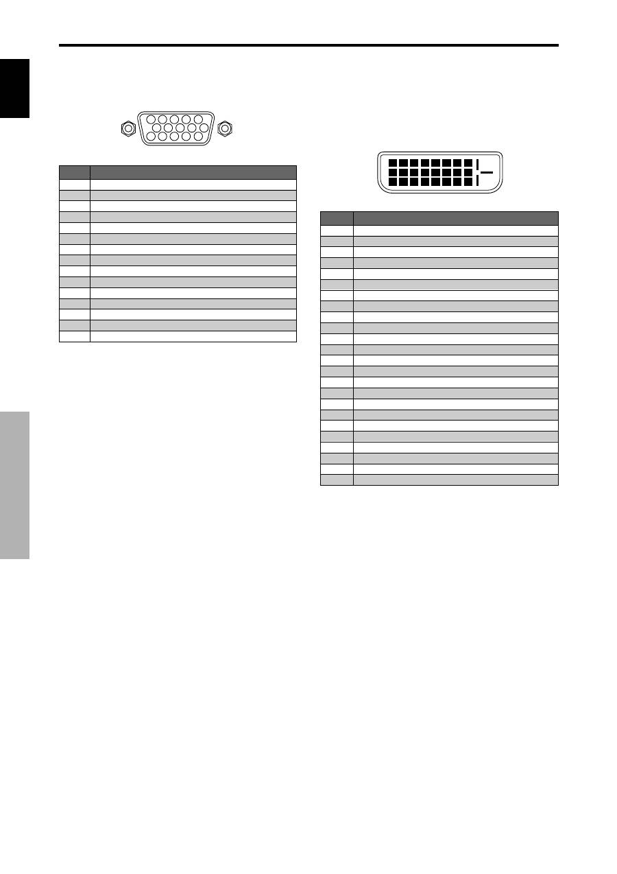
PC 1
Signal (Analog)
Red
Green or sync-on-green
Blue
No connection
Ground
Red ground
Green ground
Blue ground
No connection
Sync signal ground
No connection
Bi-directional DATA (SDA)
Horizontal sync or Composite sync
Vertical sync
Data clock
Pin No.
1
2
3
4
5
6
7
8
9
10
11
12
13
14
15
1
2
3
4
5
6
7
8
9 10 11 12 13 14 15 16
20
19
18
17
21 22 23 24
PC 3
Pin No.
1
2
3
4
5
6
7
8
9
10
11
12
13
14
15
16
17
18
19
20
21
22
23
24
Signal (Digital)
T.M.D.S Data 2 -
T.M.D.S Data 2 +
T.M.D.S Data 2 Shield
No connection
No connection
DDC Clock
DDC Data
No connection
T.M.D.S Data 1 -
T.M.D.S Data 1 +
T.M.D.S Data 1 Shield
No connection
No connection
+5V Power
Ground
Hot Plug Detect
T.M.D.S Data 0 -
T.M.D.S Data 0 +
T.M.D.S Data 0 Shield
No connection
No connection
T.M.D.S Clock Shield
T.M.D.S Clock +
T.M.D.S Clock -
mini D-Sub 15-pin connector
(Analog)
DVI-D 24-pin connector (Digital)
The unit is equipped with a type of connector commonly
used for digital.
(This cannot be used for an analog input.)
(TMDS can be used for one link only.)
Pin Assignments
Pin Assignments
English
29
En
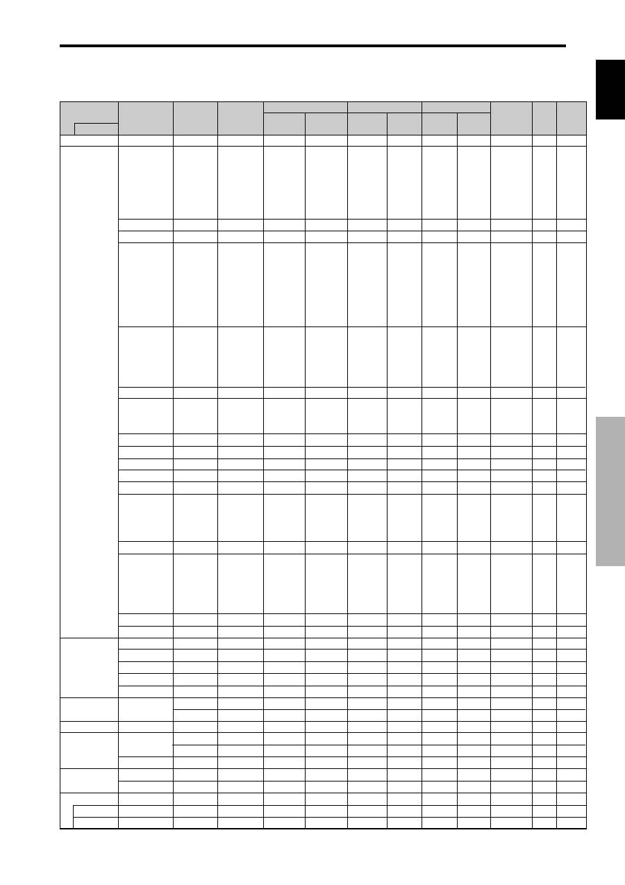
Table of Signals Supported
Table of Signals Supported
Supported resolution
• When the screen mode is NORMAL, each signal is converted to a 640 dots
480 lines signal. (Except for *
2,
*
4
)
• When the screen mode is FULL, each signal is converted to a 853 dots
480 lines signal. (Except for *
3
)
Computer input signals supported by this system
Screen mode
Dots
lines
640
400
640
480
848
480
852
480*
1
800
600
1024
768
1152
864
1280
768
1280
768*
9
1280
800*
9
1280
854*
9
1360
765
1360
768
1376
768
1280
1024
1680
1050*
9
1600
1200
1920
1200*
9
1920
1200RB*
9
640
480
832
624
1024
768
1152
870
1440
900*
9
1280
1024
1280
1024
1152
900
1280
1024
1024
768
1280
1024
768
576
640
480
Vertical
frequency
(Hz)
70.1
59.9
72.8
75.0
85.0
100.4
120.4
60.0
60.0
56.3
60.3
72.2
75.0
85.1
99.8
120.0
60.0
70.1
75.0
85.0
100.6
75.0
56.2
59.8
69.8
60.0
60.0
60.0
60.0
59.9
60.0
75.0
85.0
100.1
60.0
60.0
65.0
70.0
75.0
85.0
60.0
60.0
66.7
74.6
74.9
75.1
60.0
60.0
71.2
72.0
66.0
76.0
76.1
60.0
60.0
50.0
59.9
Horizontal
frequency
(kHz)
31.5
31.5
37.9
37.5
43.3
51.1
61.3
31.0
31.7
35.2
37.9
48.1
46.9
53.7
63.0
75.7
48.4
56.5
60.0
68.7
80.5
67.5
45.1
48.0
56.0
49.7
53.1
47.7
47.7
48.3
64.0
80.0
91.1
108.5
65.3
75.0
81.3
87.5
93.8
106.3
74.6
74.0
35.0
49.7
60.2
68.7
56.0
64.6
75.1
78.1
61.8
71.7
81.1
49.7
63.9
31.4
31.5
NORMAL
(4:3)
YES*
2
*
3
YES*
3
YES*
3
YES*
3
YES*
3
YES*
3
YES*
3
– –
– –
YES
YES
YES
YES
YES
YES
YES
YES
YES
YES
YES
YES
YES
– –
– –
– –
– –
– –
– –
– –
– –
YES*
4
YES*
4
YES*
4
YES*
4
– –
YES
YES
YES
YES
YES
– –
– –
YES*
3
YES
YES
YES
– –
YES*
4
YES*
4
YES*
4
YES
YES
YES*
4
YES
YES*
4
YES*
7
YES*
7
FULL
(16:9)
YES
YES
YES
YES
YES
YES
YES
YES*
3
YES*
3
YES
YES
YES
YES
YES
YES
YES
YES
YES
YES
YES
YES
YES
YES
YES
YES
YES
YES
YES
YES
YES
YES
YES
YES
YES
YES
YES
YES
YES
YES
YES
YES
YES
YES
YES
YES
YES
YES
YES
YES
YES
YES
YES
YES
YES
YES
YES*
7
YES*
7
RGB
select
*
5
– –
STILL
– –
STILL
– –
– –
– –
WIDE2
WIDE1
STILL
STILL
– –
– –
– –
– –
– –
STILL
– –
STILL
– –
– –
STILL
WIDE1
WIDE3
WIDE1
WIDE1
WIDE2
WIDE1
WIDE1
WIDE2
STILL
– –
– –
– –
WIDE4
– –
– –
– –
– –
– –
WIDE2
WIDE3
– –
– –
WIDE1
WIDE1
– –
– –
– –
– –
– –
– –
– –
– –
– –
– –
MOTION
Apple
Macintosh*
6,
*
8
Horizontal
NEG
NEG
NEG
NEG
NEG
NEG
NEG
POS
NEG
POS
POS
POS
POS
POS
POS
POS
NEG
NEG
POS
POS
NEG
POS
POS
POS
NEG
NEG
NEG
POS
POS
NEG
POS
POS
POS
POS
NEG
POS
POS
POS
POS
POS
NEG
NEG
Sync on G
Sync on G
Sync on G
Sync on G
NEG
NEG
NEG
– –
C Sync
C Sync
C Sync
– –
– –
NEG
NEG
Work Station
(EWS4800)*
8
Work Station (HP)*
8
Work Station
(SUN)*
8
Work Station
(SGI)
IDC-3000G
Signal Type
IBM PC/AT
compatible
computers*
8
Vertical
NEG
NEG
NEG
NEG
NEG
NEG
NEG
POS
NEG
POS
POS
POS
POS
POS
POS
POS
NEG
NEG
POS
POS
NEG
POS
POS
NEG
POS
NEG
NEG
POS
POS
POS
POS
POS
POS
POS
NEG
POS
POS
POS
POS
POS
NEG
NEG
Sync on G
Sync on G
Sync on G
Sync on G
NEG
NEG
NEG
– –
C Sync
C Sync
C Sync
– –
– –
NEG
NEG
Sync Polarity
Presence
Horizontal
YES
YES
YES
YES
YES
YES
YES
YES
YES
YES
YES
YES
YES
YES
YES
YES
YES
YES
YES
YES
YES
YES
YES
YES
YES
YES
YES
YES
YES
YES
YES
YES
YES
YES
YES
YES
YES
YES
YES
YES
YES
YES
– –
– –
– –
– –
YES
YES
YES
– –
– –
– –
– –
– –
– –
YES
YES
Vertical
YES
YES
YES
YES
YES
YES
YES
YES
YES
YES
YES
YES
YES
YES
YES
YES
YES
YES
YES
YES
YES
YES
YES
YES
YES
YES
YES
YES
YES
YES
YES
YES
YES
YES
YES
YES
YES
YES
YES
YES
YES
YES
– –
– –
– –
– –
YES
YES
YES
– –
– –
– –
– –
– –
– –
YES
YES
PAL625P
NTSC525P
Model
DVI
NO
YES
YES
YES
YES
YES
YES
YES
YES
YES
YES
YES
YES
YES
YES
YES
YES
YES
YES
YES
YES
YES
NO
YES
YES
YES
YES
NO
YES
YES
YES
YES
YES
NO
YES
YES
NO
NO
NO
NO
– –
YES
NO
NO
NO
NO
YES
YES
YES
YES
YES
YES
YES
YES
YES
NO
NO
Memory
4
5
7
8
9
41
42
19
17
11
12
13
14
15
43
44
24
25
26
27
45
51
52
80
66
21
37
22
22
53
29
30
40
47
38
54
55
56
57
58
81
88
6
16
28
39
89
29
48
59
60
61
30
62
29
31
32

English
30
En
Table of Signals Supported
*1 Only when using a graphic accelerator board that is capable of displaying 852
480.
*2 Display only 400 lines with the screen center of the vertical orientation located at the center.
*3 The picture is displayed in the original resolution. The picture will be compressed for other signals.
*4 Aspect ratio is 5:4. This signal is converted to a 600 dots
480 lines signal.
*5 Normally the RGB select mode suite for the input signals is set automatically. If the picture is not displayed properly, set the
RGB mode prepared for the input signals listed in the table above.
*6 To connect the monitor to Macintosh computer, use the monitor adapter (D-Sub 15-pin) to your computer's video port.
*7 Other screen modes (ZOOM and WIDE) are available as well.
*8 When viewing a moving picture at a vertical frequency greater than 65Hz, the picture may sometimes be unstable (jumpy).
If this occurs, please set the refresh rate of the external equipment to 60Hz.
To view 480I@60Hz (480 interlaced lines, 60Hz refresh rate) or 576I@50Hz (576 interlaced lines, 50Hz refresh rate) when
sync polarity is “Sync on Green”, set “RGB SELECT” to “MOTION”.
*9 CVT standard compliant.
NOTE:
•
While the input signals comply with the resolution listed in the table above, you may have to adjust the position and size
of the picture or the fine picture because of errors in synchronization of your computer.
•
This monitor has a resolution of 853 dots
480 lines. It is recommended that the input signal be VGA, wide VGA or
equivalent.
•
With digital input some signals are not accepted.
•
The sync may be disturbed when a nonstandard signal other than the aforementioned is input.
•
If you are connecting a composite sync signal, use the HD terminal.
What is HDCP/HDCP technology?
HDCP is an acronym for High-bandwidth Digital Content Protection. High bandwidth Digital Content Protection (HDCP) is a system
for preventing illegal copying of video data sent over a Digital Visual Interface (DVI).
If you are unable to view material via the DVI input, this does not necessarily mean the PDP is not functioning properly. With the
implementation of HDCP, there may be cases in which certain content is protected with HDCP and might not be displayed due to the
decision/intention of the HDCP community (Digital Content Protection, LLC).
* “IBM PC/AT” and “VGA” are registered trademarks of International Business Machines, Inc. of the United States.
* “Apple Macintosh” is a registered trademark of Apple Computer, Inc. of the United States.
English
31
En
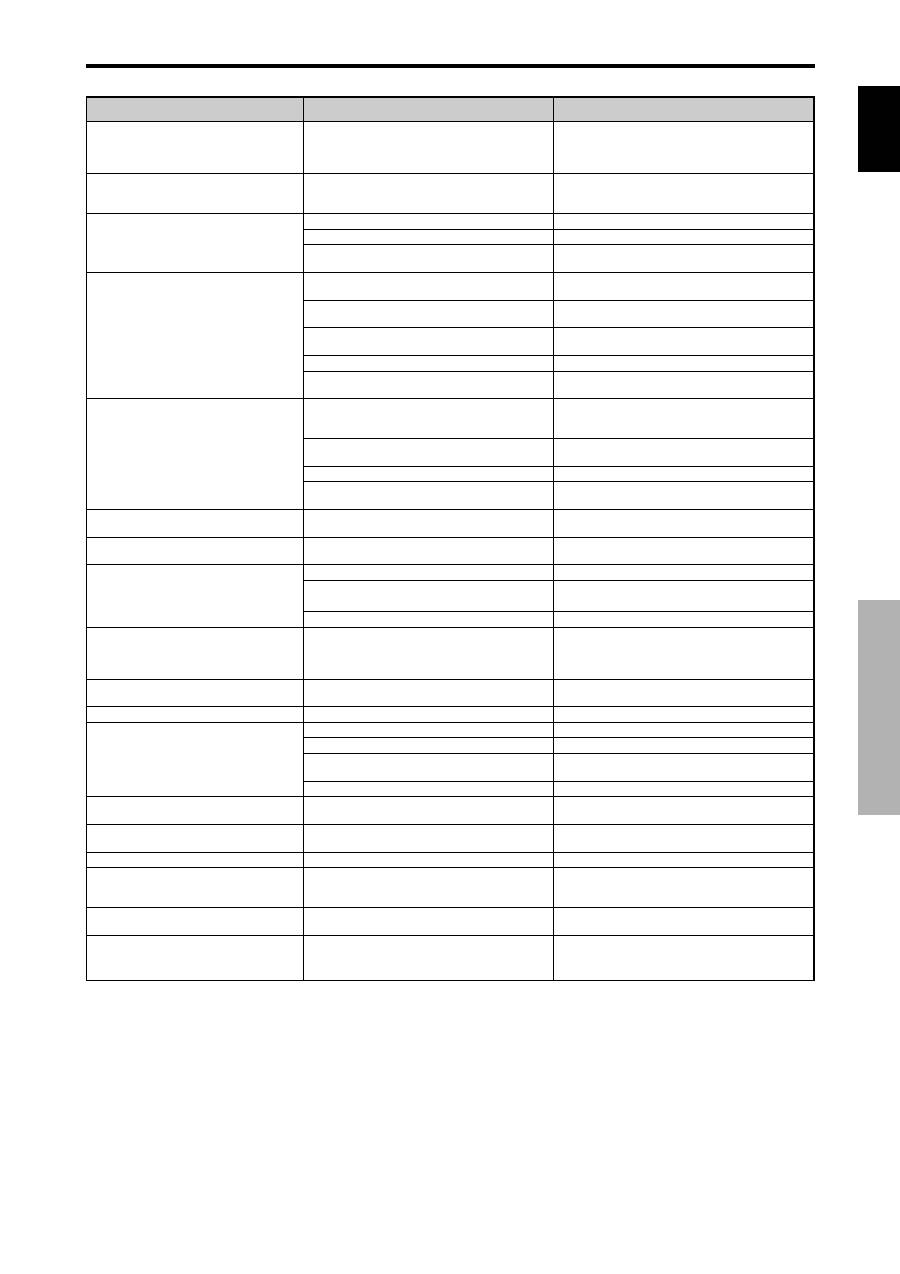
Troubleshooting
Remedy
• If there are no abnormalities in the image and sound,
the noise is caused by the cabinet reacting to
changes in temperature. This will not affect
performance.
• Leave some space between the display and the
connected components.
• Replace both batteries with new ones.
• Set IR REMOTE OFF on OPTION3 menu.
• Set an ID number with the ID NO. SET button, or set
the ID number to ALL.
• Plug the monitor’s power cord into a power outlet.
• Press the power button on the monitor to turn on the
power.
• Replace both batteries with new ones.
• Set IR REMOTE ON.
• Set an ID number with the ID NO. SET button, or set
the ID number to ALL.
• Point the remote control at the monitor’s remote
control sensor when pressing buttons, or remove the
obstacle.
• Eliminate the light by closing curtains, pointing the
light in a different direction, etc.
• Replace both batteries with new ones.
• Unplug the remote cable from the monitor.
• Set the KEY Lock to OFF.
• Plug the monitor’s power cord into a power outlet.
• Increase the volume.
• Press the remote control’s MUTING button.
• Connect the speakers properly.
• Set AUDIO INPUT on the SOUND menu correctly.
• Adjust picture control as needed.
Try another location for the monitor.
Be sure all connections are secure.
• Adjust picture controls as needed.
Check pin assignments and connections.
• Adjust the tint and color (under PICTURE).
• Turn on the computer’s power.
• Connect source to the monitor.
• Operate the computer (move the mouse, etc.).
• Set LOOP OUT OFF.
• Adjust the SCREEN properly.
• Press the SCREEN SIZE button on the remote
control and adjust properly.
• Set to the proper resolution.
• Check the input signal.
• Promptly switch off the power of the main unit and
wait until the internal temperature drops. See*1.
• Prompty switch off the power of the main unit. See
*2.
If the picture quality is poor or there is some other problem, check the adjustments, operations, etc., before requesting service.
Symptom
The unit emits a crackling sound.
Picture is disturbed.
Sound is noisy.
Remote control operates erroneously.
The remote control does not work.
Monitor’s power does not turn on when the
remote control’s power button is pressed.
Monitor does not operate when the remote
control’s buttons are pressed.
The front panel buttons of the main unit do
not function.
No sound or picture is produced.
Picture appears but no sound is produced.
Poor picture with VIDEO signal input.
Poor picture with RGB signal input.
Tint is poor or colors are weak.
Nothing appears on screen.
Part of picture is cut off or picture is not
centered.
Image is too large or too small.
Picture is unstable.
STANDBY/ON indicator is lighted in red.
STANDBY/ON indicator is blinking in red.
STANDBY/ON indicator is blinking in green
and red, or green.
Checks
• Are the image and sound normal?
• Is a connected component set directly in front or at
the side of the display?
• Are the remote control’s batteries worn out?
• Is IR REMOTE set to ON?
• Has an ID number been set for the main unit?
• Is the monitor’s power cord plugged into a power
outlet?
• Are all the monitor’s indicators off?
• Are the remote control’s batteries worn out?
• Is IR REMOTE set to OFF?
• Has an ID number been set for the main unit?
• Is the remote control pointed at the monitor, or is
there an obstacle between the remote control and
the monitor?
• Is direct sunlight or strong artificial light shining on
the monitor’s remote control sensor?
• Are the remote control’s batteries worn out?
• The remote cable is plugged into the REMOTE IN
terminal (Wired).
• The front panel buttons do not function during KEY
Lock.
• Is the monitor’s power cord plugged into a power
outlet?
• Is the volume set at the minimum?
• Is the MUTING mode set?
• Are the speakers properly connected?
• Is AUDIO INPUT set correctly?
• Improper control setting.
Local interference.
Cable interconnections.
Input impedance is not correct level.
• Improper control setting.
Incorrect RGB connector pin connections.
• Are the tint and colors properly adjusted?
• Is the computer’s power turned on?
• Is a source connected?
• Is the power management function in the standby
or off mode?
• Is LOOP OUT set to ON?
• Is the position adjustment appropriate?
• Is the screen size adjustment appropriate?
• Is the computer’s resolution setting appropriate?
• Horizontal and / or vertical sync signal is not
present when the Intelligent Power Manager
control is on.
• The temperature inside the main unit has become
too high and has activated the protector.
——————
*1 Overheat protector
If the monitor becomes too hot, the overheat protector will be activated and the monitor will be turned off. If this happens, turn off the power to the monitor
and unplug the power cord. If the room where the monitor is installed is particularly hot, move the monitor to a cooler location and wait for the monitor
to cool for 60 minutes. If the problem persists, contact your dealer.
*2 In the following case, power off the monitor immediately and contact your dealer or authorized Service Center.
The monitor turns off 5 seconds after powering on and then the STANDBY/ON indicator blinks. It indicates that the power supply circuit, plasma display
panel temperature sensor has been damaged.
Troubleshooting
English
32
En
Specifications
Specifications
Screen Size
921(H)
518(V) mm
36.3"(H)
20.4"(V) inches
diagonal 42"
Aspect Ratio
16 : 9
Resolution
853(H)
480(V) pixels
Signals
Synchronization Range
Horizontal : 15.5 to 110 kHz
(automatic : step scan)
Vertical : 50.0 to 120 Hz
(automatic : step scan)
Input Signals
RGB, NTSC (3.58/4.43), PAL (B,G,M,N),
PAL60, SECAM, HD*
1
, DVD*
1
, DTV*
1
Input Terminals
(VIDEO1 and PC1 can also be used as OUTPUT terminals)
PC
Visual 1 (Analog)
mini D-sub 15-pin
1
Visual 2 (Analog)
BNC (R, G, B, H/CS, V)
1*
2
Visual 3 (Digital)
DVI-I 24-pin
1*
3
Video
Visual 1
BNC
1
Visual 2
RCA-pin
1
Visual 3
S-Video: DIN 4-pin
1
COMPONENT
Visual 1
RCA-pin (Y, PB[CB], PR[CR])
1*
1
Visual 2
BNC (Y, PB[CB], PR[CR])
1*
1,
*
2
Audio
Stereo RCA
3(Selectable)
RS-232C
D-sub 9-pin
1
Sound output
8W+8W at 6 ohm
Power Supply
AC100-240V 50/60Hz
Current Rating
4.5A (maximum)
Power Consumption
270W (standby 0.9W)
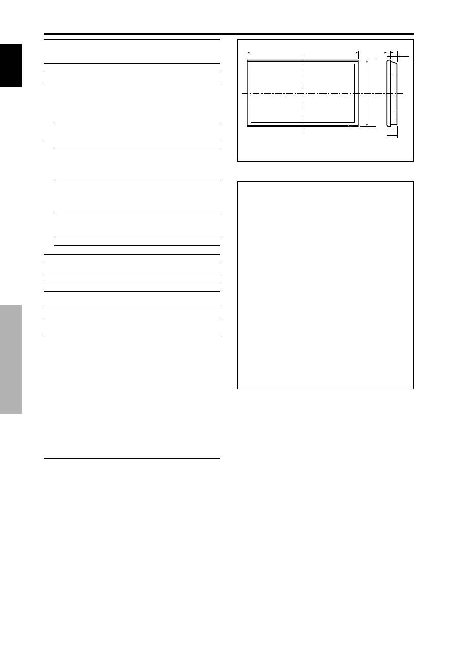
Dimensions
1018 (W)
610 (H)
89(D) mm
40 (W)
24 (H)
3.5 (D) inches
Weight
28.5 kg / 62.8 lbs (without stand)
Environmental Considerations
Operating Temperature
0°C to 40°C / 32°F to 104°F
Other Features
Motion compensated 3D Scan Converter (NTSC,
PAL, 480I, 576I, 525I, 625I, 1035I, 1080I), 2-3
pull down Converter (NTSC, 480I, 525I, 1035I,
1080I (60Hz)), 2-2 pull down Converter (PAL,
576I, 625I, NTSC, 480I, 525I), Digital Zoom
Function (100-900% Selectable), Video Wall 4-25
multi screen, Self Diagnosis, Image Burn
reduction tools (ABL LOCK1~3, INVERSE,
WHITE, ORBITER (Auto1,2/Manual), SCREEN
WIPER), Color Temperature select (high/mid/mid
low/low, user has 4 memories), Key lock (Except
power SW), Auto Picture, Input Skip, Color
Detail Adjustment, Low Tone (3 mode), Auto ID,
Programmable Timer, Gamma Correction
(4 mode), Loop through interface, Plug and play
(DDC1, DDC2b, RGB3: DDC2b only)
*
1
HD/DVD/DTV input signals supported on this
system
480P (60 Hz)
480I (60 Hz)
525P (60 Hz)
525I (60 Hz)
576P (50 Hz)
576I (50 Hz)
625P (50 Hz)
625I (50 Hz)
720P (60 Hz)
1035I (60 Hz)
1080I (50 Hz)
1080I (60 Hz)
*
2
The 5-BNC connectors are used as PC2 and
COMPONENT2 input. Select one of them under
“BNC INPUT”.
*
3
Compatable with HDCP.
Supported Signals
• 640
480P @ 59.94/60Hz
• 1920
1080I @ 50Hz
• 1280
720P @ 59.94/60Hz
• 720
576P @ 50Hz
• 1920
1080I @ 59.94/60Hz
• 1440 (720)
576I @ 50Hz
• 720
480P @ 59.94/60Hz
• 1440 (720)
480I @ 59.94/60Hz
Note:
In some cases a signal on the plasma monitor may not be displayed
properly. The problem may be an inconsistency with standards from
the source equipment (DVD, Set-top box, etc...). If you do experience
such a problem please contact your dealer and also the manufacturer of
the source equipment.
Units are in mm
(inch)
89
(3.5")
35
(1.38")
54
(2.13")
1018 (40")
610 (24")
The features and specifications may be subject to change
without notice.

Fr
Mode d’emploi
Nous vous remercions d’avoir acquis cet appareilPIONEER.
Avant d’utiliser cet écran à plasma, veuillez lire attentivement
les “Recommandations importantes” et les “Mode d’emploi”
de façon à connaître comment employer convenablement
l’écran à plasma.
Conservez le mode d’emploi pour référence. Vous pourriez
en avoir besoin plus tard.
Remarque pour le revendeur:
Après l’installation, assurez-vous de remettre ce mode d’emploi à
l’utilisateur et de lui expliquer comme utiliser ce produit.
Remarques sur l’installation:
Ce produit est vendu en assumant qu’il sera installé par un
personnel suffisamment expérimenté et qualifié. Faites toujours
réaliser le montage et l’installation par un spécialiste ou par votre
revendeur.
PIONEER ne peut être tenu responsable pour tout dommage
causé par une erreur d’installation ou de montage, une mauvaise
utilisation ou un désastre naturel.
Français
Fran
ç
ais
Recommandations importantes
Recommandations importantes
Précaution
Veuillez lire avec attention ce manuel avant d’utiliser le moniteur à
plasma et le conserver accessible pour s’y référer ultérieurement.
ATTENTION
..
RISQUE D’ELECTROCUTION
NE PAS OUVRIR
ATTENTION:
POUR EVITER TOUT RISQUE
D’ELECTROCUTION, NE PAS OUVRIR LE
BOITIER. A L’INTERIEUR, AUCUNE PIECE
NE NECESSITE L’INTER-VENTION DE
L’UTILISATEUR. EN CAS DE PROBLEME,
S’ADRESSER A UN REPARATEUR
SPECIALISTE.
Ce symbole est une mise en garde contre les
risques d’électrocution que présentent certaines
parties dépourvues d’isolation à l’intérieur de
l’appareil. Il est donc dangereux d’établir le
moindre contact avec ces parties.
Ce symbole avertit l’utilisateur que d’importantes
informations sont fournies sur le fonctionnement
ou l’entretien de cet appareil. De ce fait, il faut
lire attentivement ces instruc-tions pour éviter
tout problèm
AVERTISSEMENT
AFIN D’EVITER TOUT RISQUE D’INCENDIE OU
D’ELECTROCUTION, NE PAS EXPOSER CET APPAREIL
A LA PLUIE OU A L’HUMIDITE. NE PAS BRANCHER LA
PRISE D’ALIMENTATION POLARISEE DANS UNE PRISE
MURALE AVEC UNE RALLONGE OU UN ADAPTATEUR
MULTIPRISE SI LES FICHES NE PEUVENT ETRE
INSEREES COMPLETEMENT. EVITER D’OUVRIR LE
BOITIER CAR CELUI-CI PROTEGE DES COMPOSANTS
FONCTIONNANT A HAUTE TENSION. EN CAS DE
PROBLEME, S’ADRESSER A UN REPARATEUR
SPECIALISTE.
Avertissements et précautions de
sécurité
Ce moniteur à plasma a été conçu et fabriqu pour une utilisation
fiable et durable. Il ne nécessite aucun entretien en dehors du
nettoyage. Voir la section “Méthode de nettoyage du moniteur à
plasma” plus loin.
Le panneau à affichage plasma est constitué de fines particules
d’images (cellules) dont plus de 99,99%sont actives. Certaines
d’entre elles ne produisent pas de lumière ou restent allumées.
Pour des raisons de sécurité et pour éviter d’endommager
l’appareil, lire attentivement les instructions suivantes.
Pour éviter les risques d’éléctrocution et d’incendie:
1. Laisser suffisamment d’espace autour de l’appareil pour la
ventilation et éviter toute augmentation excessive de la température
interne. Ne pas couvrir les fentes d’aération ou installer l’appareil
dans un endroit trop exigu.
Si vous installez l’appareil dans un espace clos, assurezvous qu’il y
ait suffisamment d’espace au dessus pour permettre l’air chaud de
s’élever et de s’évacuer.
Si la température du moniteur devient excessive, la protection contre
les surchauffes entrera en action et coupera l’alimentation. Dans ce
cas, éteindre l’appareil et débrancher le câble d’alimentation. Si la
température de la pièce dans laquelle se trouve le moniteur est
particulièrement élevée, déplacer celui-ci dans un endroit plus frais
et attendre environ 60 minutes qu’il refroidisse. Si le problème
persiste, prendre contact avec votre revendeur.
2. Ne pas raccorder la prise d’alimentation polarisée de ce périphérique
à une rallonge ou une prise murale si les fiches ne peuvent pas être
complètement insérées.
3. Ne pas exposer cet appareil à la pluie ou à l’humidité.
4. Eviter d’endommager le câble d’alimentation et ne pas le modifier.
5. Débrancher le câble d’alimentation électrique pendant les orages
ou les longues périodes d’inactivité.
6. Ne pas ouvrir le boîtier protégeant les parties dangereuses
fonctionnant hauts voltages. Si l’appareil est endommagé de cette
manière, la garantie sera annulée. De plus, les risques d’électrocution
grave sont grands.
7. Ne pas essayer d’intervenir ou de réparer l’appareil. Le fabricant
décline toute responsabilité en cas de blessure corporelle ou de dégâts
matériels résultant d’une opération d’entretien quelconque effectuée
par des personnes non qualifiées ou résultant de l’ouverture du
couvercle arrière. S’adresser au service après-vente autorisé.
Pour éviter tout dommage et assurer une utilisation durable:
1. Utiliser seulement une alimentation en courant de 100-240 V 50/60
Hz. Toute utilisation prolongée avec un courant supérieur à 100-
240 V risque de diminuer la durée de vie de l’appareil et même de
provoquer un incendie.
2. Manipuler l’appareil avec précautions lors de son installation, ne
pas le laisser tomber.
3. L’installer loin de toute source de chaleur ou de poussière. Ne pas
l’exposer au soleil.
4. Eviter la pénétration de liquides ou petits objets métalliques
l’intérieur de l’appareil. En cas d’incident de ce genre, débrancher
le câble d’alimentation électrique et confier le moniteur à un service
après-vente agréé.
5. Ne pas cogner ou rayer la surface de l’écran, des déformations de
l’image en résulteraient.
6. Pour un montage et une installation correcte, il est fortement
recommandé de faire appel à un revendeur agréé et qualifié .
7. Comme c’est le cas pour tout affichage à base de phosphore (comme
un moniteur CRT, par exemple), la puissance de lumière baisse
graduellement au cours de la vie du panneau d’affichage à plasma.
8. Pour éviter tout risque de sulfuration, il est fortement conseillé de
ne pas installer l’appareil dans un vestiaire, un bain public ou un
bain de source thermale.
9. Ne pas utiliser dans un véhicule en marche car l’unité pourrait tomber
ou glisser et provoquer des blessures.
10. Pour éviter l ‘inflammation ou les chocs électriques, ne pas placer l’unité
sur la tranche, à l’envers ou avec l’écran vers le bas ou vers le haut.
i
Fr
REMARQUE:
Pour raccorder un ordinateur à ce moniteur, procéder à
l’aide d’un câble RGB à âme de ferrite aux deux extrémités.
Sur les câbles DVI et les câbles d’alimentation électrique,
fixer les âmes de ferrite fournies aux extrémités. Si vous
ne faites pas cela, le moniteur ne sera pas conforme aux
normes obligatoires CE et C-Tick.
Fixation des tores en ferrite :
Monter les tores en ferrite aux deux extrêmités du câble
DVI (non fourni) et aux deux extrêmités du câble
d’alimentation électrique (fourni).
Refermez les agrafes jusqu’ entendre un déclic.
Fixer le tore en ferrite (fourni) au câble DVI à l’aide d’un
collier.
Câble DVI (non fourni)
Connecteur
noyau (petit)
noyau (petit)
Collier
Collier
Câble d’alimentation (fourni)
tore (grande)
tore (grande)
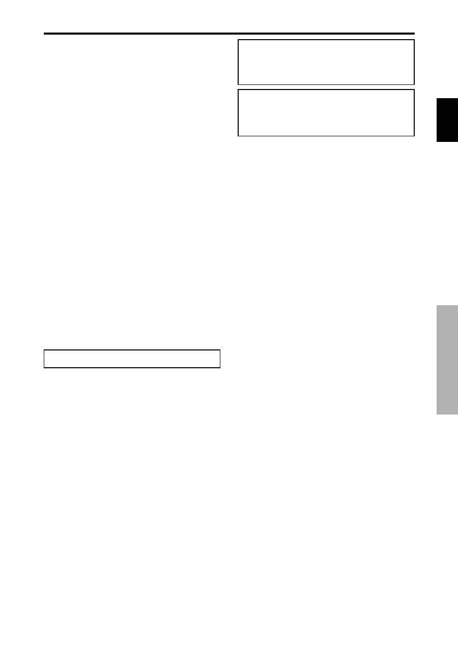
Fran
ç
ais
Recommandations importantes
Méthode de nettoyage du moniteur à plasma:
1. Utiliser un chiffon (fourni) ou un chiffon doux et sec pour nettoyer
le panneau avant et le cadre. Ne jamais utiliser de solvants de type
alcool ou diluant pour le nettoyage de ces surfaces.
2. Nettoyer les prises d’aération du plasma en procédant à l’aide d’une
brosse à poils doux fixée à un aspirateur.
3. Pour garantir la bonne ventilation du moniteur, nettoyer les prises
d’air tous les mois. Un nettoyage plus fréquent peut s’avérer
nécessaire selon les conditions environnantes dans lesquelles le
moniteur à plasma est utilisé.
Pour éviter les risques de brûlage du luminophore, les mesures
suivantes sont recommandées:
Comme tous les périphériques d’affichage à base luminophore et tous les
autres affichages gaz plasma, les moniteurs plasma peuvent être sujets au
brûlage du luminophore dans certaines circonstances. Certaines conditions
d’utilisation, telles que l’affichage continu d’une image statique pour une
durée prolongée, peuvent causer le brûlage du luminophore si aucune
précaution n’est prise. Pour protéger votre investissement dans ce moniteur
à plasma, veuillez suivre les directives et les conseils suivantes pour
minimiser l’occurence le marquage de l’écran
* S’assurer de mettre en marche et d’utiliser l’économiseur d’écran
chaque fois que c’est possible, pendant l’utilisation avec une source
d’entrée venant d’ un ordinateur.
* Afficher une image en mouvement aussi souvent que possible.
* Changer la position de l’affichage de menu de temps à autre.
* Toujours couper l’alimentation après la fin de l’utilisation du
moniteur.
Si le moniteur à plasma est en usage continu ou de longue durée, prendre
les mesures suivantes afin d’éviter l’occurence le brûlage du
luminophore:
* Abaisser le niveau de l’image (contraste, luminance) autant que
possible, sans faire perdre la lisibilit de l’image.
* Afficher une image avec de nombreuses couleurs et graduations de
couleur. (par ex. des images photo-graphiques ou photo-réalistes).
* Créer un contenu d’image avec un contraste minimal entre les zones
sombres et les zones claires, par exemple des caractères blancs sur
un fond noir. Utiliser des couleurs complémentaires ou pastels le
plus souvent possible.
* Eviter d’afficher des images avec peu de couleurs et des limites nettes
et clairement définies entre les couleurs.
* REMARQUE: Le brûlage de l’écran n’est pas couvert par la
garantie.
Contactez un revendeur agréé ou un revendeur de marque pour d'autres
procédures qui conviendront le mieux à vos besoins particuliers.
Attention
Cet modèle est fait pour être utilisé avec les accessoires
optionnels suivants. Toute utilisation avec d’autres
accessoires optionnels peut entraîner une instabilité pouvant
causer des blessures.
Haut-parleurs: PDP-S32-LR
Support plateau: PDK-TS09
Unité de montage mural: PDK-WM04
Unité de montage incliné: PDK-WT01
Unité de montage au plafond: PDK-CK01
ii
Fr
AVERTISSEMENT:
EN POSITIONNANT L’EQUIPEMENT, S’ASSURER QUE
LA FICHE ET LA PRISE DE RACCORDEMENT DE
L’ALIMENTATION SONT FACILEMENT ACCESSIBLES.
Ce produit est conforme à la directive relative aux
appareils basse tension (73/23/CEE), à la directive
CE relative à la compatibilité electromagnétique (89/
336/CEE, amendements 92/31/CEE et 93/68/CEE).
