Pioneer PLASMA DISPLAY: Information
Information: Pioneer PLASMA DISPLAY
Table of contents
- Precautions Important Information Warnings and Safety Precaution
- NOTE:
- Caution
- Contents
- How to use the safety metal fittings and the screws for safety metal fittings Ventilation Requirements for enclosure mounting Installation
- Creating a video wall Cable Management
- Caution on when the plasma monitor is installed vertically How to use the remote control
- Front View Part Names and Function
- Information Rear View/ Terminal Board
- Remote Control
- Basic Operations POWER VOLUME MUTING DISPLAY DIGITAL ZOOM AUTO SET UP OFF TIMER
- SCREEN SIZE Operation WIDE Operations
- SCREEN SIZE Operation with Computer Signals
- Menu Operations OSD (On Screen Display) Controls Setting the language for the menus
- Menu Tree
- Main menu
- Picture Settings Menu
- SOUND Settings Menu SCREEN Settings Menu
- Option1 Settings Menu
- Information
- Option2 Settings Menu
- ORBITER INVERSE
- SCREEN WIPER SOFT FOCUS
- Option3 Settings Menu
- PROGRAM TIMER
- Information
- DIVIDER DISP. MODE
- SCREEN ABL LINK
- REPEAT TIMER Advanced OSD Settings Menu Color System Settings Menu Source Information Menu
- mini D-Sub 15-pin connector (Analog) DVI-D 24-pin connector (Digital) Pin Assignments
- Table of Signals Supported Supported resolution
- Table of Signals Supported
- Troubleshooting
- Specifications
English
OSD (On Screen Display) Controls
24
En
Enabling/disabling remote control wireless
transmission
This function enables/disables remote control wireless
transmission.
Example: Setting “OFF”
Set “ADVANCED OSD” to “ON” in the main menu (1/
2), then perform the following operations.
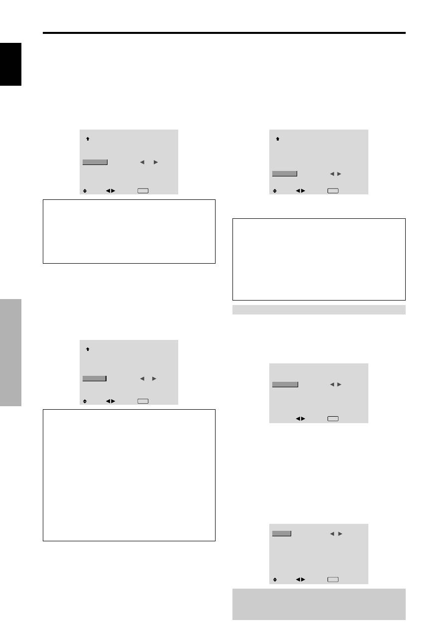
On “IR REMOTE” of “OPTION3” menu, select “OFF”, then
press the MENU/SET button.
OPTION3
3 / 3
PREVIOUS PAGE
TIMER
PWR. ON MODE
KEY LOCK
IR REMOTE
LOOP OUT
ID NUMBER
VIDEO WALL
: LAST
: OFF
:
OFF
: OFF
: ALL
SEL.
ADJ.
EXIT RETURN
Information
IR REMOTE settings
ON:
Enables remote control wireless transmission.
OFF:
Disables remote control wireless transmission.
Set “OFF” to avoid unwanted control from other remote
controls.
Loop Out setting
When this feature is set to ON, the received signal will be
looped out.
Example: Setting “ON”
Set “ADVANCED OSD” to “ON” in the main menu (1/
2), then perform the following operations.
On “LOOP OUT” of “OPTION3” menu, select “ON”.
OPTION3
3 / 3
PREVIOUS PAGE
TIMER
PWR. ON MODE
KEY LOCK
IR REMOTE
LOOP OUT
ID NUMBER
VIDEO WALL
: LAST
: OFF
: ON
:
ON
: ALL
SEL.
ADJ.
EXIT RETURN
Information
LOOP OUT settings
ON:
The received signal will be looped out via PC1
terminal or VIDEO1 terminal.
OFF:
The received signal will not loop out.
* Even if LOOP OUT is ON, signals won’t be sent out if
POWER is being turned off.
To connect another display...
See page 3.
If the PC1 signal is present at the time the
power switched on...
The PC1 input will be displayed regardless of the setting
of LOOP OUT.
ID number setting
When using more than one of these displays, this function
sets ID numbers so that operation of the remote control
does not cause multiple monitors to operate at the same
time.
Example: Setting “2”
Set “ADVANCED OSD” to “ON” in the main menu (1/
2), then perform the following operations.
On “ID NUMBER” of “OPTION3” menu, select “2”.
OPTION3
3 / 3
PREVIOUS PAGE
TIMER
PWR. ON MODE
KEY LOCK
IR REMOTE
LOOP OUT
ID NUMBER
VIDEO WALL
: LAST
: OFF
: ON
: OFF
:
2
SEL.
ADJ.
EXIT RETURN
*
To reset back to ALL
Press the CLEAR button.
Information
ID NUMBER settings
ALL:
ID NUMBER will not be set.
1 to 256:
ID NUMBER will be set.
When the ID NUMBER have been set
You can also set ID NUMBER for each remote control
to operate the plasma display individually. To do so,
see below.
To set the ID number for the remote control
Example: Setting “2”
Press the ID NO. SET button on the remote control.
The “ID NO. SET” screen appears.
On “ID NUMBER” of “ID NO. SET” menu, select “2”.
ID NO.SET
POSITION : 1
:
2
ID NUMBER
ADJ.
EXIT RETURN
*
To reset back to ALL
Press the CLEAR button.
Video Wall setting
Use this feature to configure a 4-25 video wall.
Set “ADVANCED OSD” to “ON” in the main menu (1/
2), then perform the following operations.
On “OPTION3” menu, select “VIDEO WALL”, then press
the MENU/SET button.
The “VIDEO WALL” screen appears.
VIDEO WALL
DIVIDER
POSITION
DISP. MODE
AUTO ID
SCREEN
P. ON DELAY
ABL LINK
REPEAT TIMER
:
1
: NORMAL
: OFF
: OFF
: OFF
: OFF
SEL.
ADJ.
EXIT RETURN
Note:
A contingency method of shutting off the electric
power should be used in cases of emergency during video
wall setup.
