Pioneer PLASMA DISPLAY: Creating a video wall Cable Management
Creating a video wall Cable Management: Pioneer PLASMA DISPLAY
Table of contents
- Precautions Important Information Warnings and Safety Precaution
- NOTE:
- Caution
- Contents
- How to use the safety metal fittings and the screws for safety metal fittings Ventilation Requirements for enclosure mounting Installation
- Creating a video wall Cable Management
- Caution on when the plasma monitor is installed vertically How to use the remote control
- Front View Part Names and Function
- Information Rear View/ Terminal Board
- Remote Control
- Basic Operations POWER VOLUME MUTING DISPLAY DIGITAL ZOOM AUTO SET UP OFF TIMER
- SCREEN SIZE Operation WIDE Operations
- SCREEN SIZE Operation with Computer Signals
- Menu Operations OSD (On Screen Display) Controls Setting the language for the menus
- Menu Tree
- Main menu
- Picture Settings Menu
- SOUND Settings Menu SCREEN Settings Menu
- Option1 Settings Menu
- Information
- Option2 Settings Menu
- ORBITER INVERSE
- SCREEN WIPER SOFT FOCUS
- Option3 Settings Menu
- PROGRAM TIMER
- Information
- DIVIDER DISP. MODE
- SCREEN ABL LINK
- REPEAT TIMER Advanced OSD Settings Menu Color System Settings Menu Source Information Menu
- mini D-Sub 15-pin connector (Analog) DVI-D 24-pin connector (Digital) Pin Assignments
- Table of Signals Supported Supported resolution
- Table of Signals Supported
- Troubleshooting
- Specifications
English
Installation
3
En
Note:
1. The VIDEO1 and PC1 terminals can be used for either INPUT or OUTPUT.
When LOOP OUT is ON, do not connect an OUTPUT signal from another unit, that will place an extraordinary load on
the other unit and may damage it.
2. LOOP OUT can not be turned ON while signals are input to the PC1 terminal.
3. LOOP OUT can be turned ON while signals are input to the PC1 terminal if the POWER is switched ON.
Information
• To loop signals out to another plasma display, set the LOOP OUT to ON.
• To create a video wall, set the VIDEO WALL menu items properly.
• To connect monitors, please use a 1~2m (3.3~6.6 feet) BNC cable (any commercially available cable).
• If the image quality is poor, do not use the monitor’s out terminal. Use a distribution amplifier (any commercially
available distribution amplifier) to connect the split signals to the respective monitor INPUT terminals.
• Being used as a video wall function, maximaly 4-screen is rough-standard with lower than 1024
768, 60Hz
signal.
• A distribution amplifier is particularly recommended when using 9-screen and over video wall.
• From the second monitor onward, connections require a BNC-RCA conversion cable or connector, a mini D-Sub
15 pin cable-BNC (
5) cable or a conversion connector.
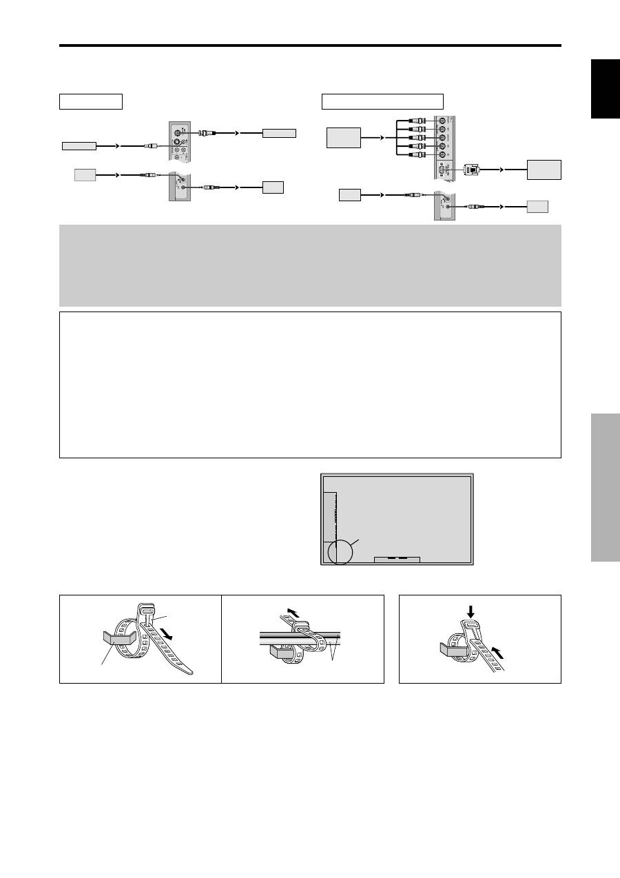
Creating a video wall
With built-in matrix display capability, you can create a 4-25 video wall.
• Connect signal cables and remote cables as shown below.
Video signal
PC/COMPONENT signal
BNC connector
RCA phono plug
OUT
VIDEO signal
IN
OUT
Remote
control
VIDEO signal
Remote
IN
control
BNC connector
PC signal /
IN
OUT
OUT
Remote
control
COMPONENT
signal
PC signal /
COMPONENT
signal
IN
Remote
control
Cable Management
Using the cable clamps provided with the plasma display,
bundle at the back of the unit the signal and audio cables
connected to the display.
Back of the unit
mounting hooks
To attach
To detach
clamp
mounting hook
cables
1.
2.
