Indesit FMR 54 K.A AV: Installation
Installation: Indesit FMR 54 K.A AV
Installation
GB
! Please keep this instruction booklet in a safe place for
future reference. If the appliance is sold, given away or
moved, please make sure the booklet is also passed on to
contained within it.
! Please read this instruction manual carefully: it contains
important information concerning the safe operation,
installation and maintenance of the appliance.
Positioning
!
should be disposed of in accordance with local separated
!
accordance with the instructions provided. Incorrect installation
may damage property or cause harm to people or animals.
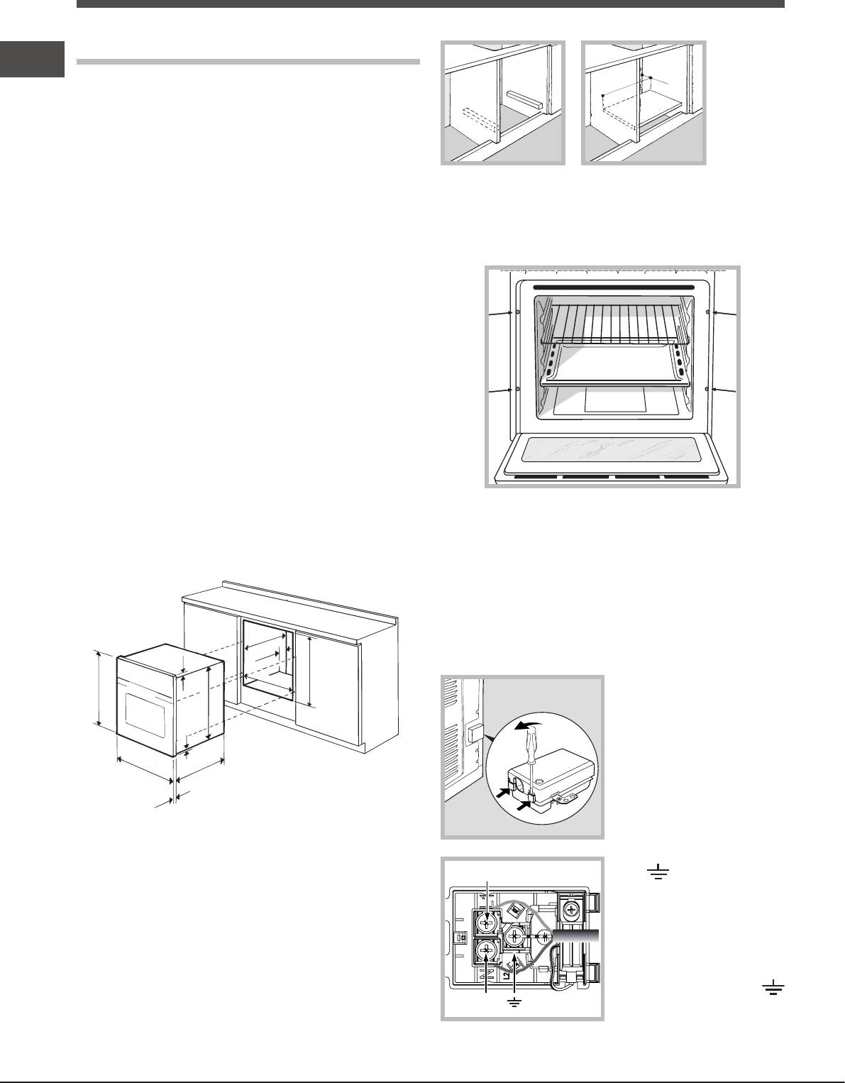
Built-in appliances
Use an appropriate cabinet to ensure that the appliance
operates properly:
resistant material.
glues which can withstand temperatures of up to 100°C.
under the counter
in a kitchen unit, the cabinet must have the following
dimensions:
16
595 mm.
595 mm.
25 mm.
45 mm.
560 mm.
Secure the appliance to the cabinet by opening the oven
door and inserting 4 screws into the 4 holes on the outer
frame.
! All parts which ensure the safe operation of the appliance
must not be removable without the aid of a tool.
Electrical connection
Ovens equipped with a three-pole power supply cable are
designed to operate with alternating current at the voltage
and frequency indicated on the data plate located on the
547 mm. min.
Fitting the power supply cable
45 mm.
23 mm.
558 mm.
1. Open the terminal board
575-585 mm.
by inserting a screwdriver
567 mm.
into the side tabs of the
cover. Use the screwdriver
5 mm.
as a lever by pushing it
545 mm.
2. Install the power supply
* Stainless steel models only
cable by loosening the
cable clamp screw and the
! The appliance must not come into contact with electrical
three wire contact screws
parts once it has been installed.
L
L-N-
.
The indications for consumption given on the data plate
Connect the wires to the
have been calculated for this type of installation.
corresponding terminals:
the Blue wire to the terminal
Ventilation
To ensure adequate ventilation, the back panel of the
cabinet must be removed. It is advisable to install the oven
so that it rests on two strips of wood, or on a completely
to the terminal marked
N
3. Secure the cable by fastening the clamp screw.
4. Close the cover of the terminal board.
GB
Connecting the supply cable to the mains
Install a standardised plug corresponding to the load
The appliance must be directly connected to the mains using
an omnipolar switch with a minimum contact opening of 3
mm installed between the appliance and the mains. The
switch must be suitable for the charge indicated and must
must be positioned so that it does not come into contact
! The installer must ensure that the correct electrical
connection has been performed and that it is fully compliant
with safety regulations.
Before connecting the appliance to the power supply, make
sure that
the law.
appliance, which is indicated on the data plate.
on the data plate.
If the socket is incompatible with the plug, ask an
authorised technician to replace it. Do not use extension
cords or multiple sockets.
! Once the appliance has been installed, the power supply
cable and the electrical socket must be easily accessible.
! The cable must not be bent or compressed.
! The cable must be checked regularly and replaced by
! The manufacturer declines any liability should these
safety measures not be observed.
17
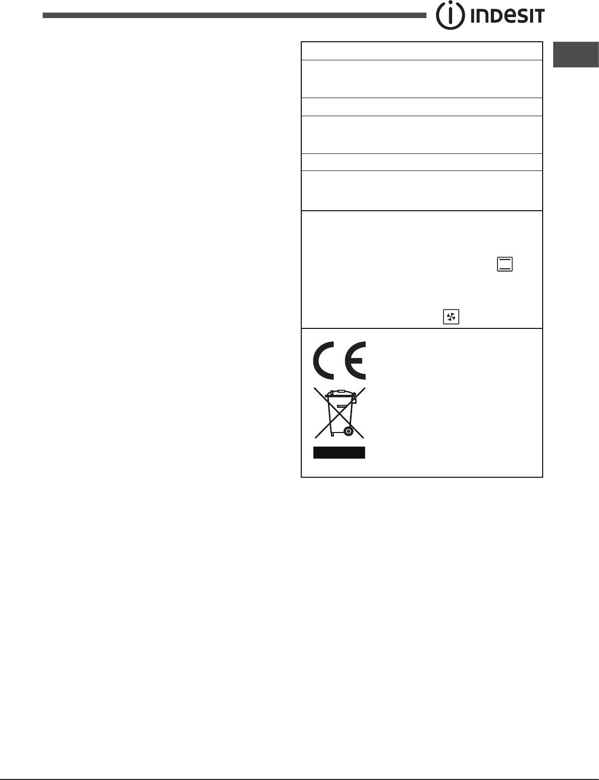
APPLIANCE SPECIFICATIONS
width 43.5 cm
Dimensions*
height 32,4 cm
depth 40.6 cm
Volume*
58 l
width 45.5 cm
Dimensions**
height 32,4 cm
depth 40.6 cm
Volume**
60 l
voltage: 220-240V~ 50/60 Hz or 50Hz
Electrical
(see data plate) maximum power
connections
absorbed 2250 W
Directive 2002/40/EC on the label
of electric ovens. Standard EN 50304
Energy consumption for Natural
ENERGY
convection – heating mode:
LABEL
Traditional mode
Declared energy consumption for
Forced convection Class –
heating mode: Fan assisted.
This appliance conforms to the
following European Economic
Community directives:
- 2006/95/EEC dated 12/12/06 (Low
Voltage) and subsequent amendments.
- 2004/108/EEC dated 03/05/89
(Electromagnetic Compatibility) and
subsequent amendments.
- 93/68/EEC dated 22/07/93 and
subsequent amendments.
- 2012/19/EC and subsequent
amendments.
- 1275/2008 standby/off mode.
* Only for models with drawn rails.
** Only for models with wire rails.


