Pioneer VSX-520-S – page 3
Manual for Pioneer VSX-520-S
Table of contents
- IMPORTANT VENTILATION CAUTION
- Operating Environment
- Contents
- Flow of settings on the receiver
- Chapter 1: Before you start
- Before you start01 Ventilation
- Chapter 2: Controls and displays
- Controls and displays02 Operating range of remote control
- Controls and displays 02 Display
- Controls and displays02
- Remote control
- Controls and displays02
- Controls and displays 02
- Chapter 3: Connecting your equipment Placing the speakers
- Hints on the speaker placement
- Connecting the speakers
- Making cable connections
- HDMI cables About HDMI Analog audio cables
- Digital audio cables About video outputs connection
- Connecting a TV and playback components Connecting using HDMI Connecting your component with no HDMI terminal
- Connecting a satellite receiver Connecting an HDD/DVD or other digital set-top box recorder, VCR and other video sources
- Using the component video jacks Connecting other audio components
- Connecting antennas
- Plugging in the receiver
- Chapter 4: Basic Setup Automatically setting up for surround sound (MCACC)
- Basic Setup04
- Chapter 5: Listening to your system Basic playback
- Auto playback Listening in surround sound
- Listening to your system 05
- Using Front Stage Surround Advance Listening in stereo
- Using Stream Direct Better sound using Phase Control Using the Sound Retriever
- Using surround back channel processing Listening with Acoustic Calibration EQ
- Setting the Audio options Setting the Up Mix function
- Setting What it does Option(s)
- Setting What it does Option(s)
- Choosing the input signal Using the headphone
- Chapter 6: The System Setup menu Using the System Setup menu Manual speaker setup
- Speaker setting
- Crossover network Channel level Speaker distance
- The Input Assign menu The Pre Out Setting
- Chapter 7 Using the tuner Listening to the radio Saving station presets
- Using the tuner07
- An introduction to RDS
- Using the tuner07 Displaying RDS information
- Chapter 8: Making recordings Making an audio or a video recording
- Chapter 9: Other connections
- Connecting Optional Bluetooth ADAPTER
- Other connections09
- Chapter 10: Additional information Troubleshooting Problem Remedy
- Problem Remedy
- Additional information 10
- HDMI Symptom Remedy
- Resetting the main unit
- Specifications Cleaning the unit

The System Setup menu 06
41
En
English
Français
Español
Crossover network
When the surround back speakers are
connected:
•Default setting: 100Hz
L
C
R
SR
SBR
SBL
SL
SW
This setting decides the cutoff between bass
sounds playing back from the speakers
When the front height speakers are connected:
selected as LARGE, or the subwoofer, and bass
L
FHL
C
FHR
R
SR
SL
SW
sounds playing back from those selected as
1
Adjust the level of each speaker as the test
SMALL.
It also decides where the cutoff will
3
tone is emitted.
be for bass sounds in the LFE channel.
1 Select ‘X.OVER’ from the SP SETUP menu.
Tip
2Use
/
to choose the frequency cutoff
• You can change the channel levels at any
point.
time by press , then press CH
Frequencies below the cutoff point will be sent
SELECT and LEV +/– on the remote
to the subwoofer (or LARGE speakers).
control. You can also press CH SELECT
and use / to select the channel, and
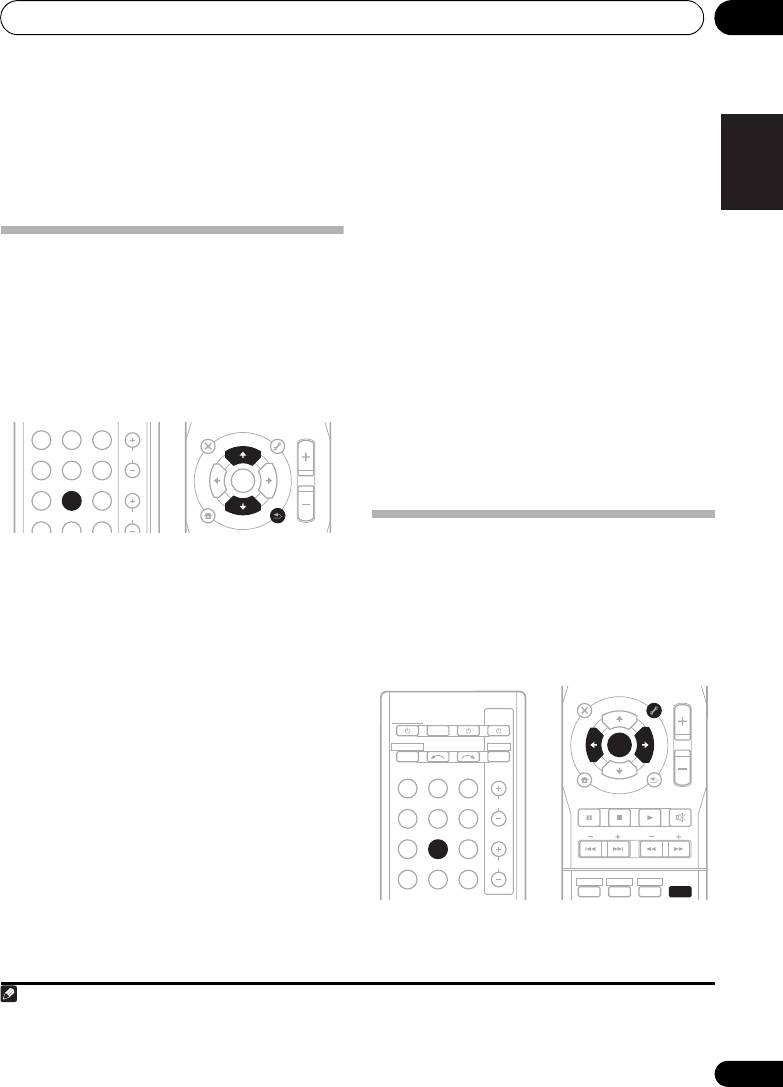
Channel level
then use / to adjust the channel
Using these settings, you can adjust the overall
levels.
balance of your speaker system.
1 Select ‘CH LEVEL’ from the SP SETUP
Speaker distance
menu.
For good sound depth and separation from
your system, you need to specify the distance
2Use
/
to select a setup option.
of your speakers from the listening position.
• T. TONE M – Move the test tone manually
The receiver can then add the proper delay
from speaker to speaker and adjust
needed for effective surround sound.
individual channel levels.
• T. TONE A – Adjust channel levels as the
1 Select ‘SP DISTN.’ from the SP SETUP
test tone moves from speaker to speaker
menu.
automatically.
2Use
/
to choose the speaker that you
3 Confirm your selected setup option.
want then set the distance.
2
The test tones will start after you press ENTER.
Use / to adjust the distance of each
speaker (in 0.1 m increments).
4 Adjust the level of each channel using
/.
If you selected T. TONE M, use / to switch
speakers.
The T. TONE A setup outputs test tones in the
following order (depends on speaker settings).
Note
1 For more on selecting the speaker sizes, see Speaker setting on page 40.
2 After the volume increases to the reference level, test tones will be output.
3 • If you are using a Sound Pressure Level (SPL) meter, take the readings from your main listening position and adjust the level
of each speaker to 75 dB SPL (C-weighting/slow reading).
• The subwoofer test tone is output at low volumes. You may need to adjust the level after testing with an actual soundtrack.
RECEIVER
VSX-520_SYXCN_En.book 41 ページ 2010年4月12日 月曜日 午後7時13分

VSX-520_SYXCN_En.book 42 ページ 2010年4月12日 月曜日 午後7時13分42
The System Setup menu06
• For the assignment of the digital signal
inputs, see Choosing the input signal on
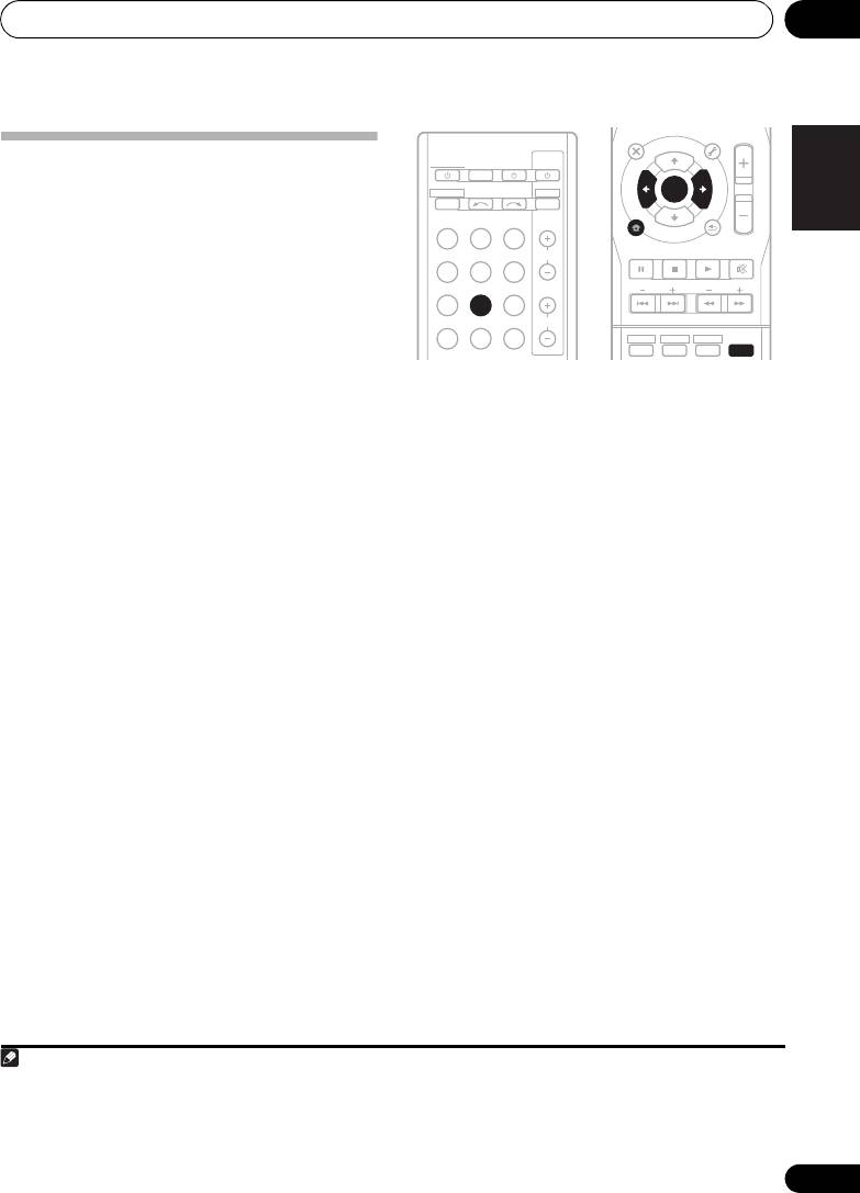
The Input Assign menu
page 38.
You only need to make settings in the Input
Assign menu if you didn’t hook up your
equipment according to the default settings for
the component video inputs.
The Pre Out Setting
Specify either using the surround back speaker
• Default settings:
or the front height speaker connection with the
COMP 1 – BD
PRE OUT outputs. An additional amplifier is
COMP 2 – DVD
required for the speaker connection.
If you didn’t make component video
•Default setting: SURR.BACK (Surround
connections according to the defaults above,
back)
you must assign the numbered input to the
1 Select ‘PRE OUT’ from the System Setup
component you’ve connected (or else you may
menu.
see the video signal of a different component).
For more on this, see Using the component
2 Select which speaker to connect to the
video jacks on page 24.
PRE OUT outputs using
/
.
• SURR.BACK – Connect the surround back
1 Select ‘IN ASSIG’ from the System Setup
speaker.
menu.
• HEIGHT – Connect the front height
2 Select ‘COMP. IN’ from the IN ASSIG
speaker.
menu.
3Use
/
to select the number of the
component video input to which you’ve
connected your video component.
The numbers correspond with the numbers
beside the inputs on the rear of the receiver.
4 Select the component that corresponds
with the one you connected to that input.
•Use the / buttons and ENTER to select
BD, DVD, TV, DVR or OFF.
• If you assign a component input to a
certain function, any component inputs
previously assigned to that function will
automatically be switched off.
• Make sure you have connected the audio
from the component to the corresponding
inputs on the rear of the receiver.
• If you connect any source component to
the receiver using a component video
input, you should also have your TV
connected to this receiver’s COMPONENT
VIDEO OUT jacks.
42
En
Using the tuner 07
43
En
English
Français
Español
Chapter
7
:
Using the tuner
High speed tuning
Press and hold TUNE / for high speed
Listening to the radio
tuning. Release the button at the
The following steps show you how to tune in to
frequency you want.
FM and AM radio broadcasts using the
automatic (search) and manual (step) tuning
Improving FM stereo sound
functions. Once you are tuned to a station you
If the TUNE or ST indicators don’t light when
can memorize the frequency for recall later—
tuning to an FM station because the signal is
see Saving station presets below for more on
weak, press the BAND button to select FM
how to do this.
MONO and set the receiver to the mono
BD DVD TV
AUDIO
TUNER EDIT
MASTER
PARAMETER
TOOLS
VOLUME
reception mode. This should improve the
MENU
TOP
T
U
N
E
MENU
DVR CD
CD-R
CH
sound quality and allow you to enjoy the
E
T
P
R
E
broadcast.
E
S
ENTER
R
T
E
S
ADAPTER
TUNER
EQ
P
HOME
PHASE
S.RETRIEVER SIGNAL SEL
VOL
MENU
T
U
N
E
SETUP
BAND
RETURN
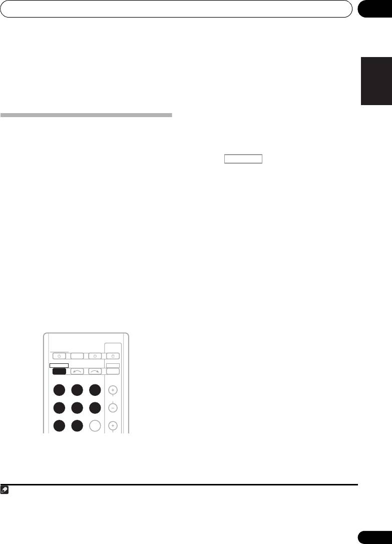
Saving station presets
1 Press
TUNER
to select the tuner.
If you often listen to a particular radio station,
it’s convenient to have the receiver store the
2Use
BAND
to change the
BAND
(FM or
frequency for easy recall whenever you want to
AM), if necessary.
listen to that station. This saves the effort of
Each press switches the band between FM
manually tuning in each time. This unit can
(stereo or mono) and AM.
1
memorize up to 30 stations.
3 Tune to a station.
There are three ways to do this:
Automatic tuning
To search for stations in the currently
selected band, press and hold TUNE /
for about a second. The receiver will start
searching for the next station, stopping
when it has found one. Repeat to search for
other stations.
Manual tuning
To change the frequency one step at a
time, press TUNE /.
Note
VSX-520_SYXCN_En.book 43 ページ 2010年4月12日 月曜日 午後7時13分
AUDIO
TUNER EDIT
MASTER
PARAMETER
TOOLS
VOLUME
MENU
TOP
T
U
N
E
MENU
RECEIVER
TV
SOURCESLEEP
CONTROL
T
P
E
R
S
E
RECEIVER
INPUT SELECT
DTV/TV
E
ENTER
S
R
T
E
P
INPUT
BD DVD
TV
HOME
MENU
T
U
N
E
BAND
SETUP
RETURN
PTY SEARCH
DVR CD
CD-R
CH
MUTE
ADAPTER
TUNER
EQ
BASS
TRE
PHASE
S.RETRIEVER SIGNAL SEL
VOL
HDD
DVD
VCR
1
2
3
DISP
1 • If the receiver is left disconnected from the AC power outlet for over a month, the station memories will be lost and will have
to be reprogrammed.
• Stations are stored in stereo. When the station is stored in the FM MONO mode, it shows as ST when recalled.

VSX-520_SYXCN_En.book 44 ページ 2010年4月12日 月曜日 午後7時13分
Using the tuner07
1 Tune to a station you want to memorize.
Tip
See Listening to the radio on page 43 for more
on this.
• To erase a station name, follow steps 1 and
2, and press ENTER while the display is
2Press
TUNER EDIT
.
blank. Press TUNER EDIT while the display
The display shows PRESET, then a blinking
is blank, to keep the previous name.
MEM and station preset.
• Once you have named a station preset,
3Press
PRESET /
to select the station
Press DISP to show the name. When you
preset you want.
want to return to the frequency display,
You can also use the number buttons.
press DISP several times to show the
frequency.
4Press
ENTER
.
After pressing ENTER, the preset number stop
blinking and the receiver stores the station.
Listening to station presets
You will need to have some presets stored to do
this. See Saving station presets on page 43 if
you haven’t done this already.
•Press
PRESET /
to select the station
preset you want.
• You can also use the number buttons on
the remote control to recall the station
preset.
Naming preset stations
For easier identification, you can name all of
your preset stations.
1 Choose the station preset you want to
name.
See Listening to station presets above for how
to do this.
2Press
TUNER EDIT
twice.
The cursor at the first character position is
blinking on the display.
3 Input the name you want.
Choose a name up to eight characters long.
•Use the PRESET / buttons to select
character position.
•Use the TUNE / buttons to select
characters.
• The name is stored when ENTER is
pressed.
44
En
Using the tuner 07
45
En
English
Français
Español
An introduction to RDS
Radio Data System (RDS) is a system used by
most FM radio stations to provide listeners with
various kinds of information—the name of the
station and the kind of show they’re
broadcasting, for example.
One feature of RDS is that you can search by
type of program. For example, you can search
for a station that’s broadcasting a show with
the program type, JAZZ.
1
You can search the following program types:
Searching for RDS programs
NEWS – News
FINANCE – Stock market
You can search for a program type listed
AFFAIRS – Current Affairs
reports, commerce,
above.
INFO – General
trading, etc.
Information
CHILDREN – Programs for
1Press
TUNER
then press
BAND
to select
SPORT – Sport
children
2
the FM band.
EDUCATE – Educational
SOCIAL – Social affairs
DRAMA – Radio plays, etc.
RELIGION – Programs
2Press
PTY SEARCH
.
CULTURE – National or
concerning religion
SEARCH shows in the display.
regional culture, theater,
PHONE IN – Public
etc.
expressing their views by
3Press
PRESET /
to select the program
SCIENCE – Science and
phone
type you want to hear.
technology
TRAVEL – Holiday-type
VARIED – Usually talk-
travel rather than traffic
4Press
ENTER
to search for the program
based material, such as
announcements
type.
quiz shows or interviews.
LEISURE – Leisure interests
POP M – Pop music
and hobbies
The system starts searching through the
ROCK M – Rock music
JAZZ – Jazz
station presets for a match, stopping when it
EASY M – Easy listening
COUNTRY – Country
was found one. Repeat to search for other
LIGHT M – ‘Light’ classical
music
stations.
music
NATION M – Popular
CLASSICS – ‘Serious’
music in a language other
If NO PTY is displayed it means the tuner
classical music
than English
couldn’t find that program type at the time of
OTHER M – Music not
OLDIES – Popular music
3
the search.
fitting above categories
from the ’50s and ’60s
WEATHER – Weather
FOLK M – Folk music
reports
DOCUMENT –
Documentary
Note
RECEIVER
TV
SOURCESLEEP
CONTROL
RECEIVER
INPUT SELECT
DTV/TV
INPUT
BD DVD
TV
DVR CD
CD-R
CH
ADAPTER
TUNER
EQ
PHASE
S.RETRIEVER SIGNAL SEL
VOL
1 In addition, there are three other program types, ALARMTST, ALARM, and NO TYPE. ALARM and ALARMTST are used for
emergency announcements. NO TYPE appears when a program type cannot be found.
2 RDS is only possible in the FM band.
3 RDS searches station presets only. If no stations have been preset, or if the program type could not be found among the station
presets NO PTY is displayed. FINISH means the search is complete.
AUDIO
TUNER EDIT
MASTER
PARAMETER
TOOLS
VOLUME
U
N
E
MENU
TOP
T
MENU
T
P
E
R
E
E
S
ENTER
S
R
T
E
P
HOME
MENU
T
U
N
E
BAND
SETUP
RETURN
PTY SEARCH
MUTE
BASS
TRE
HDD
DVD
VCR
1
2
3
DISP
VSX-520_SYXCN_En.book 45 ページ 2010年4月12日 月曜日 午後7時13分

Using the tuner07
Displaying RDS information
Use the DISP button to display the different
1
types of RDS information available.
•Press
DISP
for RDS information.
Each press changes the display as follows:
• Listening mode
•Master volume
• Radio Text (RT) – Messages sent by the
radio station. For example, a talk radio
station may provide a phone number as RT.
• Program Service Name (PS) – The name of
the radio station.
•Program Type (PTY) – This indicates the
kind of program currently being broadcast.
• Current tuner frequency (FREQ)
46
En
Note
VSX-520_SYXCN_En.book 46 ページ 2010年4月12日 月曜日 午後7時13分
1 • If any noise is picked up while displaying the RT scroll, some characters may be displayed incorrectly.
• If you see NO TEXT in the RT display, it means no RT data is sent from the broadcast station. The display will automatically
switch to the PS data display (if no PS data, NO NAME is displayed).
• In the PTY display, NO PTY may be shown.
Making recordings 08
47
En
English
Français
Español
Chapter 8:
Making recordings
1 Select the source you want to record.
Use the MULTI CONTROL buttons (or INPUT
Making an audio or a video
SELECTOR).
recording
2 Select the input signal (if necessary).
You can make an audio or a video recording
Press the button then press
from the built-in tuner, or from an audio or
SIGNAL SEL to select the input signal
video source connected to the receiver (such
1
corresponding to the source component (see
as a CD player or TV).
page 38 for more on this).
Keep in mind you can’t make a digital
recording from an analog source or vice-versa,
3 Prepare the source you want to record.
so make sure the components you are
Tune to the radio station, load the CD, video,
recording to/from are hooked up in the same
DVD etc.
way (see Connecting your equipment on
4 Prepare the recorder.
page 16 for more on connections).
Insert a blank tape, MD, video etc. into the
If you want to record a video source, you also
2
recording device and set the recording levels.
need to use the same type of connection for the
Refer to the instructions that came with the
source as for the recorder. For example, you
recorder if you are unsure how to do this. Most
can’t record a component hooked up to
video recorders set the audio recording level
composite video jacks with a recorder hooked
automatically—check the component’s
up to the component video outputs (see
instruction manual if you’re unsure.
page 23 for more on video connections).
5 Start recording, then start playback of the
source component.
Note
1 If you are recording a video source, you need to use the same type of connection for the source as for the recorder. For example,
you can’t record a component hooked up to composite video jacks with a recorder hooked up to the component video outputs
(see Connecting an HDD/DVD recorder, VCR and other video sources on page 23 for more on video connections).
TV
RECEIVER
SOURCESLEEP
CONTROL
RECEIVER
INPUT SELECT
DTV/TV
INPUT
BD DVD
TV
DVR CD
CD-R
CH
ADAPTER
TUNER
EQ
2 The receiver’s volume, balance, tone (bass, treble, loudness), and surround effects have no effect on the recorded signal.
RECEIVER
VSX-520_SYXCN_En.book 47 ページ 2010年4月12日 月曜日 午後7時13分
Other connections09
Chapter 9:
Other connections
CAUTION
• Before making or changing the connections,
switch off the power. Plugging in
components should be the last connection
you make with your system.
• Do not allow any contact between speaker
wires from different terminals.
Bluetooth
® ADAPTER for
Wireless Enjoyment of Music
Important
• Do not move the receiver with the
Bluetooth ADAPTER connected. Doing so
could cause damage or faulty contact.
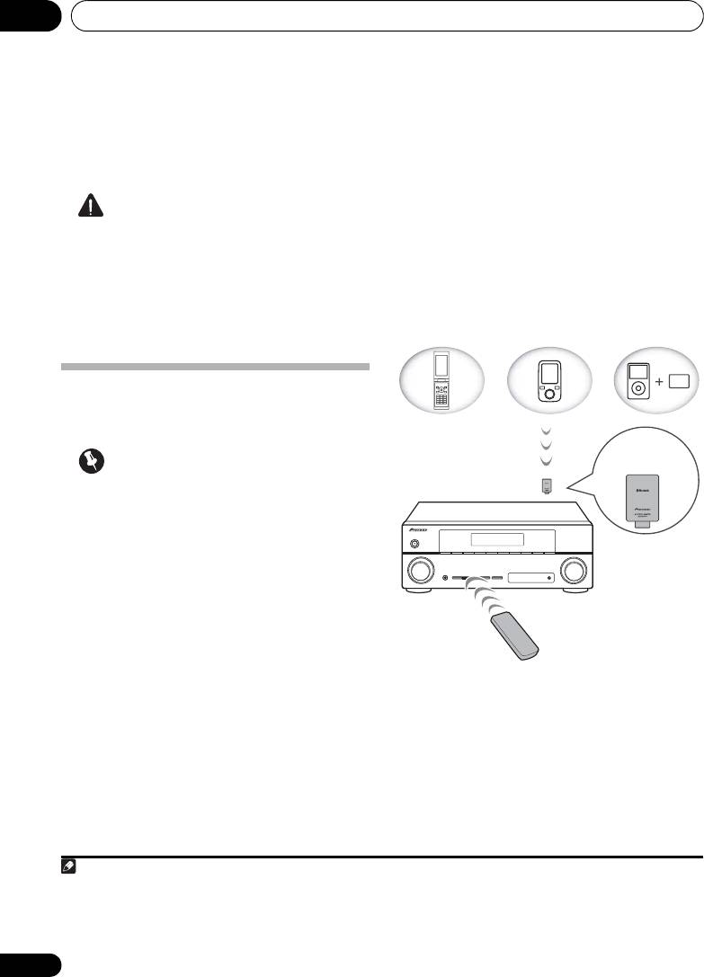
Wireless music play
When the Bluetooth ADAPTER (Pioneer Model
No. AS-BT100) is connected to this unit, a
product equipped with Bluetooth wireless
technology (portable cell phone, digital music
player, etc.) can be used to listen to music
1
wirelessly.
Also, by using a commercially
Remote control operation
available transmitter supporting Bluetooth
wireless technology, you can listen to music on
The remote control supplied with this unit
a device not equipped with Bluetooth wireless
allows you to play and stop media, and perform
2
technology. The AS-BT100 model supports
other operations.
SCMS-T contents protection, so music can
also be enjoyed on devices equipped with
SCMS-T type Bluetooth wireless technology.
48
En
Note
1 • It must be necessary that the Bluetooth wireless technology enabled device supports A2DP profiles.
• Pioneer does not guarantee proper connection and operation of this unit with all Bluetooth wireless technology enabled
devices.
2 • It must be necessary that the Bluetooth wireless technology enabled device supports AVRCP profiles.
• Remote control operations cannot be guaranteed for all Bluetooth wireless technology enabled devices.
Device not
equipped with
Bluetooth wireless
technology:
Digital music
Bluetooth
Bluetooth wireless
player
wireless
technology
+
technology
enabled device:
Bluetooth audio
enabled device:
Digital music
transmitter
cell phone
player
(sold commercially)
®
Music data
Bluetooth
ADAPTER
This receiver
Remote control
operation
VSX-520_SYXCN_En.book 48 ページ 2010年4月12日 月曜日 午後7時13分
Other connections 09
49
En
English
Français
Español
Connecting Optional
Bluetooth
Bluetooth wireless technology device to
2
enable Bluetooth communications.
For more
ADAPTER
details, see also the operating instructions of
• Before making or changing connections,
your Bluetooth wireless technology device.
switch off the power.
1 Press TOP MENU.
2Press
ENTER
to enter
PAIRING
.
3 Select the PIN code to be used from 0000/
1234/8888 using
/
, then press ENTER.
PAIRING blinks.
Important
• You can use any of 0000/1234/8888 PIN
codes. Bluetooth wireless technology
device using any other PIN code cannot
be used with this system.
4 Switch on the
Bluetooth
wireless
technology device that you want to make
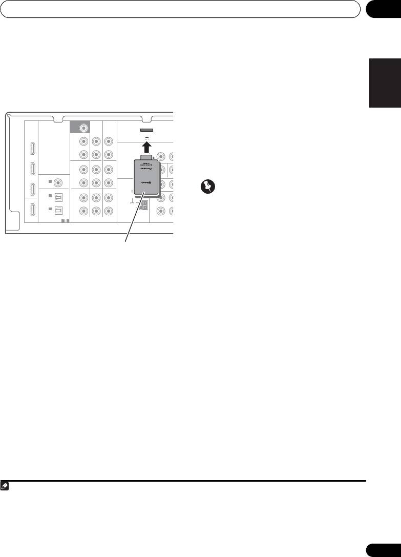
1 Switch the receiver into standby and
pairing, place it near the system and set it
connect
Bluetooth
ADAPTER to the
ADAPTER
into the pairing mode.
PORT
located in the rear panel.
5 Check to see that the
Bluetooth
ADAPTER
2 Switch on the receiver.
is detected by the
Bluetooth
wireless
technology device.
3 Press
ADAPTER
on the remote control to
1
When Bluetooth wireless technology device is
switch the receiver to ADAPTER input mode.
connected:
Bluetooth wireless technology device name
Pairing
Bluetooth
ADAPTER and
3
appears in the receiver display.
Bluetooth
wireless technology
When Bluetooth wireless technology device is
device
not connected:
“Pairing” must be done before you start
playback of Bluetooth wireless technology
NODEVICE appears in the receiver display. In
content using Bluetooth ADAPTER. Make sure
this case, perform the connection operation
to perform pairing first time you operate the
from the side of the Bluetooth wireless
system or any time pairing data is cleared.
technology device.
“Pairing” is the step necessary to register
Note
SURR BACK /
FRONT
BD
HEIGHT
L
(
Single
)
OUT
R
CD
DVR/VCR
L
IN
IN
MONITOR OUT
DV
P
R
P
B
R
TV/SAT
DVD BD
IN
L
IN
IN
R
1 When the Bluetooth ADAPTER is not plugged into the ADAPTER PORT, NO ADAPTER will be displayed if ADAPTER input
mode is selected.
D
COMPONENT VI
D
SUBWOOFER
PRE OUT
CD-R/TAPE
DVR/VCR
ADAPTER PORT
(
OUTPUT 5 V 100 mA MAX
)
VIDEO
DVR/VCR
OUT I
DVD
PRE OUT
CD-R/TAPE
COAXIAL
ASSIGNABLE
TV/SAT
IN
1
ANTENNA
(
CD
)
FM
UNBAL
OPTICAL
75
IN
2
OUT
(
DVR/VCR
)
AM
IN
1
LOOP
(
CD-R/TAPE
)
ASSIGNABLE
HDMI
1 2
AUDIO
N
This receiver
®
Bluetooth
ADAPTER
VSX-520_SYXCN_En.book 49 ページ 2010年4月12日 月曜日 午後7時13分
2 • Pairing is required when you first use Bluetooth wireless technology device and Bluetooth ADAPTER.
• To enable Bluetooth communication, pairing should be done with both of your system and Bluetooth wireless technology
device.
3 The system can display alphanumeric characters only. Other characters may not be displayed correctly.

Other connections09
6From the
Bluetooth
wireless technology
device list, select
Bluetooth
ADAPTER and
1
enter the PIN code selected in the step 4.
Listening to Music Contents of
Bluetooth
wireless technology
device with Your System
1Press
ADAPTER
on the remote control to
switch the receiver to ADAPTER input mode.
2 Perform the connection operation from
the side of the
Bluetooth
wireless technology
device to the
Bluetooth
ADAPTER.
3 Start playback of music contents stored in
Bluetooth
wireless technology device.
The following operations are now possible for
Bluetooth wireless technology devices, using
2
the remote controller.
®
The Bluetooth
word mark and logos are
registered trademarks owned by Bluetooth
SIG, Inc. and any use of such marks by Pioneer
Corporation is under license. Other
trademarks and trade names are those of their
respective owners.
50
En
Note
VSX-520_SYXCN_En.book 50 ページ 2010年4月12日 月曜日 午後7時13分
Button What it does
/ Starts normal playback and pauses/
unpauses playback.
Press to skip to the start of the current
file, then previous files. Press and hold
to start fast reverse scanning.
Press to skip to the next file. Press and
hold to start fast forward scanning.
1 PIN code may in some case be referred to as PASSKEY.
2• Bluetooth wireless technology device should be compatible with AVRCP profile.
• Depending on Bluetooth wireless technology device you use, operation may differ from what is shown in this table.

Additional information 10
51
En
English
Français
Español
VSX-520_SYXCN_En.book 51 ページ 2010年4月12日 月曜日 午後7時13分
Chapter 10:
Additional information
Troubleshooting
Incorrect operations are often mistaken for trouble and malfunctions. If you think that there is
something wrong with this component, check the points below. Sometimes the trouble may lie
in another component. Investigate the other components and electrical appliances being used.
If the trouble cannot be rectified even after exercising the checks listed below, ask your nearest
Pioneer authorized service center or your dealer to carry out repair work.
• If the unit does not operate normally due to external effects such as static electricity
disconnect the power plug from the outlet and insert again to return to normal operating
conditions.
Problem Remedy
The power does not turn
• Disconnect the power plug from the outlet, and insert again.
on.
• Make sure there are no loose strands of speaker wire touching the rear
panel. This could cause the receiver to shut off automatically.
• If the power shuts off automatically, take the unit to your nearest
Pioneer authorized service center or your dealer for servicing.
No sound is output when a
• Make sure the component is connected correctly (refer to Connecting
function is selected.
your equipment on page 16).
• Press MUTE on the remote control to turn muting off.
• Press SIGNAL SEL to select the proper input signal (see Choosing the
input signal on page 38).
No image is output when a
• Make sure the component is connected correctly (refer to Connecting
function is selected.
your equipment on page 16).
• Select the correct component (use the MULTI CONTROL buttons).
• Check The Input Assign menu on page 42 to make sure you’re assigned
the correct input.
• The video input selected on the TV monitor is incorrect. Refer to the
instruction manual supplied with the TV.
Considerable noise in radio
• Connect the antenna (page 25) and adjust the position for best
broadcasts.
reception.
• Route any loose cables away from the antenna terminals and wires.
• Fully extend the FM wire antenna, position for best reception, and
secure to a wall (or connect an outdoor FM antenna).
• Connect an additional internal or external AM antenna (page 25).
• Turn off equipment causing interference or move it away from the
receiver (or move antennas farther away from equipment causing noise).

VSX-520_SYXCN_En.book 52 ページ 2010年4月12日 月曜日 午後7時13分
Additional information10
Problem Remedy
Broadcast stations cannot
• Connect an outdoor antenna (refer to page 25).
be selected automatically.
No sound from surround or
• Connect the speakers properly (refer to page 18).
center speakers.
• Refer to Speaker setting on page 40 to check the speaker settings.
• Refer to Channel level on page 41 to check the speaker levels.
No sound from subwoofer. • Make sure the subwoofer is switched on.
• If the subwoofer has a volume knob, make sure it’s turned up.
• The Dolby Digital or DTS source you are listening to may not have an
LFE channel.
• Switch the subwoofer setting in Speaker setting on page 40 to YES or
PLUS.
• Switch the LFEATT (LFE Attenuate) on page 36 to LFEATT 0 or LFEATT 5.
The PHASE CONTROL
• If applicable, check that the lowpass filter switch on your subwoofer is
feature doesn’t seem to
off, or the lowpass cutoff is set to the highest frequency setting. If there is
have an audible effect.
a PHASE setting on your subwoofer, set it to 0º (or depending on the
subwoofer, the setting where you think it has the best overall effect on the
sound).
• Make sure the speaker distance setting is correct for all speakers (see
Speaker distance on page 41).
Noise during playback of a
• Move the cassette deck further from your receiver, until the noise
cassette deck.
disappears.
No sound is output or a
• Set the digital volume level of the player to full, or to the neutral
noise is output when
position.
software with DTS is played
• Make sure the player’s settings are correct and/or the DTS signal out is
back.
on. Refer to the instruction manual supplied with the DVD player.
• Set the input signal type to C1/O1/O2 (DIGITAL) (see Choosing the
input signal on page 38).
During a playback search,
• This is not a malfunction, but be sure to turn the volume down to
noise is output from a DTS
prevent the output of loud noise from your speakers.
compatible CD player.
Everything seems to be set
• Check that the positive/negative speaker terminals on the receiver are
up correctly, but the
matched with the corresponding terminals on the speakers (see
playback sound is odd.
Connecting the speakers on page 18).
Can’t operate the remote
• Replace the batteries (refer to page 10).
control.
• Operate within 7 m, 30°
of the remote sensor on the front panel (refer to
page 7).
• Remove the obstacle or operate from another position.
• Avoid exposing the remote sensor on the front panel to direct light.
The display is dark or off. • Press DIMMER on the remote control repeatedly to return to the
default.
52
En

Additional information 10
53
En
English
Français
Español
VSX-520_SYXCN_En.book 53 ページ 2010年4月12日 月曜日 午後7時13分
Problem Remedy
The Bluetooth wireless
• Check that no object that emits electromagnetic waves in the 2.4 GHz
technology device cannot
band (microwave oven, wireless LAN device or Bluetooth wireless
be connected or operated.
technology apparatus) is near the unit. If such an object is near the unit,
Sound from the Bluetooth
set the unit far from it. Or, stop using the object emitting the
wireless technology device
electromagnetic waves.
is not emitted or the sound
• Check that the Bluetooth wireless technology device is not too far from
is interrupted.
the unit and that obstructions are not set between the Bluetooth wireless
technology device and the unit. Set the Bluetooth wireless technology
device and the unit so that the distance between them is less than about
10 m and no obstructions exist between them.
• Check that the Bluetooth ADAPTER and the ADAPTER PORT of the unit
are correctly connected.
• The Bluetooth wireless technology device may not be set to the
communication mode supporting the Bluetooth wireless technology.
Check the setting of the Bluetooth wireless technology device.
• Check that pairing is correct. The pairing setting was deleted from this
unit or the Bluetooth wireless technology device. Reset the pairing.
• Check that the profile is correct. Use a Bluetooth wireless technology
device that supports A2DP profile and AVRCP profile.

VSX-520_SYXCN_En.book 54 ページ 2010年4月12日 月曜日 午後7時13分
Additional information10
HDMI
Symptom Remedy
No picture or sound. • If the problem still persists when connecting your HDMI component
directly to your monitor, please consult the component or monitor
manual or contact the manufacturer for support.
No picture. • Video signals that are input from the analog video terminal will not
output from the HDMI terminal. Signals that are input from the HDMI
terminal will not output from the analog video terminal. Be consistent
with the type of cable between input and output.
• Depending in the output settings of the source component, it may be
outputting a video format that can’t be displayed. Change the output
settings of the source, or connect using the component or composite
jacks.
•
This receiver is HDCP-compatible. Check that the components you are
connecting are also HDCP-compatible. If they are not, please connect
them using the component or composite video jacks.
•
Depending on the connected source component, it’s possible that it
will not work with this receiver (even if it is HDCP-compatible). In this
case, connect using the component or composite video jacks between
source and receiver.
•
If video images do not appear on your TV, try adjusting the resolution,
Deep Color or other setting for your component.
• To output signals in Deep Color, use an HDMI cable (High Speed
®
HDMI
Cable) to connect this receiver to a component or TV with the
Deep Color feature.
No sound, or sound
• If you’ve made separate connections for audio, make sure you have
suddenly ceases.
assigned the analog/digital jack(s) to the corresponding HDMI input for
the component.
• Check the audio output settings of the source component.
• Check that the Audio Parameter setting is set to HDMI AMP/THRU
(refer to page 37).
• If the component is a DVI device, use a separate connection for the audio.
• HDMI format digital audio transmissions require a longer time to be
recognized. Due to this, interruption in the audio may occur when
switching between audio formats or beginning playback.
• Turning on/off the device connected to this unit’s HDMI OUT terminal
during playback, or disconnecting/connecting the HDMI cable during
playback, may cause noise or interrupted audio.
54
En

Additional information 10
55
En
English
Français
Español
Important information regarding
the HDMI connection
Resetting the main unit
There are cases where you may not be able to
Use this procedure to reset all the receiver’s
route HDMI signals through this receiver (this
settings to the factory default. Use the front
depends on the HDMI equipped component
panel controls to do this.
you are connecting-check with the
1 Switch the receiver into standby.
manufacturer for HDMI compatibility
information).
2 While holding down the
BAND
button,
If you aren’t receiving HDMI signals properly
press and hold the
STANDBY/ON button
through this receiver (from your component),
for about two seconds.
please try the following configuration when
3 When you see RESET? appear in the
connecting up.
display, press
AUTO/DIRECT
.
1
Configuration
OK? shows in the display.
Connect your HDMI-equipped component
4Press
STEREO/ALC
to confirm.
directly to the display using an HDMI cable.
OK appears in the display to indicate that the
Then use the most convenient connection
receiver has been reset to the factory default
(digital is recommended) for sending audio to
settings.
the receiver. See the operating instructions for
more on audio connections. Set the display
volume to minimum when using this
configuration.
Note
VSX-520_SYXCN_En.book 55 ページ 2010年4月12日 月曜日 午後7時13分55
1 • If your display only has one HDMI terminal, you can only receive HDMI video from the connected component.
• Depending on the component, audio output may be limited to the number of channels available from the connected display
unit (for example audio output is reduced to 2 channels for a monitor with stereo audio limitations).
• If you want to switch the input source, you’ll have to switch functions on both the receiver and your display unit.
• Since the sound is muted on the display when using the HDMI connection, you must adjust the volume on the display every
time you switch input sources.
VSX-520_SYXCN_En.book 56 ページ 2010年4月12日 月曜日 午後7時13分56
Additional information10
Furnished Parts
Microphone (for Auto MCACC setup) . . . . . . . . 1
Specifications
Remote control . . . . . . . . . . . . . . . . . . . . . . . . . . 1
Audio section
Dry cell batteries (AAA size IEC R03). . . . . . . 2
Rated power output
AM loop antenna . . . . . . . . . . . . . . . . . . . . . . . . . 1
Front, Center, Surround
FM wire antenna . . . . . . . . . . . . . . . . . . . . . . . . . 1
. . . . . . . . 130 W per channel (1 kHz, 6
Ω
, 1 %)
Power cord . . . . . . . . . . . . . . . . . . . . . . . . . . . . . . 1
. . . . . . . . . . . . . . . . . . . . . . 100 W per channel
Warranty card . . . . . . . . . . . . . . . . . . . . . . . . . . . 1
(20 Hz to 20 kHz, 8
Ω
, 0.09 %)
These operating instructions
Total Harmonic Distortion
. . . . . . 0.06 % (20 Hz to 20 kHz, 8
Ω
, 95 W/ch)
Note
Frequency response (LINE Pure Direct mode)
• The specifications are applicable when the
. . . . . . . . . . . . . . . . . . . . 5 Hz to 100 kHz dB
power supply is 230 V.
Guaranteed speaker impedance . . . . 6
Ω
to 16
Ω
• Specifications and the design are subject
Input (Sensitivity/Impedance)
to possible modifications without notice,
LINE . . . . . . . . . . . . . . . . . . . . . . 200 mV/47 kΩ
due to improvements.
Output (Level/Impedance)
REC . . . . . . . . . . . . . . . . . . . . . . 200 mV/2.2 kΩ
Signal-to-Noise Ratio
(IHF, short circuited, A network)
Cleaning the unit
LINE . . . . . . . . . . . . . . . . . . . . . . . . . . . . . 98 dB
• Use a polishing cloth or dry cloth to wipe
off dust and dirt.
Video section
Signal level
• When the surface is dirty, wipe with a soft
Composite . . . . . . . . . . . . . . . . . . 1 Vp-p (75 Ω)
cloth dipped in some neutral cleanser
Component Video . . . . . . . . . Y: 1.0 Vp-p (75 Ω)
diluted five or six times with water, and
PB, PR: 0.7 Vp-p (75 Ω)
wrung out well, and then wipe again with a
Corresponding maximum resolution
dry cloth. Do not use furniture wax or
Component Video . . 1080i (1125i)/720p (750p)
cleansers.
Tuner section
• Never use thinners, benzine, insecticide
Frequency Range (FM) . . . 87.5 MHz to 108 MHz
sprays or other chemicals on or near this
Antenna Input (FM) . . . . . . . . .75 Ω unbalanced
unit, since these will corrode the surface.
Frequency Range (AM). . . . 531 kHz to 1602 kHz
Antenna (AM) . . . . . . . . . . . . . . . . .Loop antenna
Digital In/Out section
Published by Pioneer Corporation.
HDMI terminal . . . . . . . . . . . . . . .Type A (19-pin)
Copyright © 2010 Pioneer Corporation.
HDMI output type . . . . . . . . . . . . . . . 5 V, 100 mA
All rights reserved.
Miscellaneous
Power Requirements
. . . . . . . . . . . . AC 220 V to 230 V, 50 Hz/60 Hz
Power Consumption. . . . . . . . . . . . . . . . . . 240 W
In standby . . . . . . . . . . . . . . . . . . . . . . . .0.45 W
Dimensions
. . . . .420 mm (W) x 158 mm (H) x 347.7 mm (D)
Weight (without package) . . . . . . . . . . . . . 8.9 kg
56
En

Additional information 10
57
En
English
Français
Español
VSX-520_SYXCN_En.book 57 ページ 2010年4月12日 月曜日 午後7時13分
VSX-520_SYXCN_Fr.book 2 ページ 2010年4月12日 月曜日 午後7時14分
IMPORTANT
ATTENTION
DANGER D´ELECTROCUTION
NE PAS OUVRIR
Ce symbole de l’éclair, placé dans un
ATTENTION :
Ce point d’exclamation, placé dans un
triangle équilatéral, a pour but d’attirer
POUR ÉVITER TOUT RISQUE
triangle équilatéral, a pour but d’attirer
l’attention de l’utilisateur sur la présence, à
D’ÉLECTROCUTION, NE PAS ENLEVER LE
l’attention de l’utilisateur sur la présence,
l’intérieur du coffret de l’appareil, de
COUVERCLE (NI LE PANNEAU ARRIÈRE).
dans les documents qui accompagnent
“tensions dangereuses” non isolées d’une
AUCUNE PIÈCE RÉPARABLE PAR
l’appareil, d’explications importantes du
grandeur suffisante pour représenter un
L’UTILISATEUR NE SE TROUVE À
point de vue de l’exploitation ou de
risque d’électrocution pour les êtres
L’INTÉRIEUR. CONFIER TOUT ENTRETIEN À
l’entretien.
humains.
UN PERSONNEL QUALIFIÉ UNIQUEMENT.
D3-4-2-1-1_A1_Fr
AVERTISSEMENT
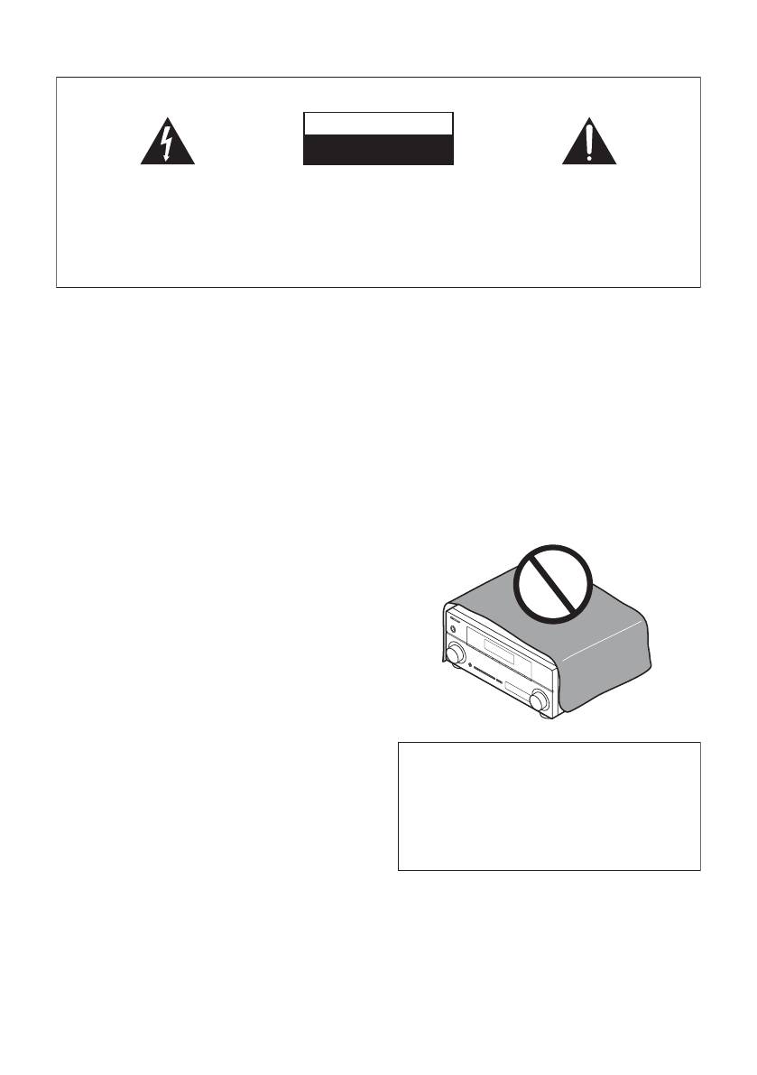
PRÉCAUTION DE VENTILATION
Cet appareil n’est pas étanche. Pour éviter les risques
Lors de l’installation de l’appareil, veillez à laisser un
d’incendie et de décharge électrique, ne placez près de
espace suffisant autour de ses parois de manière à
lui un récipient rempli d’eau, tel qu’un vase ou un pot
améliorer la dissipation de chaleur (au moins 40 cm sur
de fleurs, et ne l’exposez pas à des gouttes d’eau, des
le dessus, 10 cm à l’arrière et 20 cm de chaque côté).
éclaboussures, de la pluie ou de l’humidité.
D3-4-2-1-3_A1_Fr
AVERTISSEMENT
Les fentes et ouvertures du coffret sont prévues pour la
ventilation, pour assurer un fonctionnement stable de
AVERTISSEMENT
l’appareil et pour éviter sa surchauffe. Pour éviter les
Avant de brancher l’appareil pour la première, lisez
risques d’incendie, ne bouchez jamais les ouvertures et
attentivement la section suivante.
ne les recouvrez pas d’objets, tels que journaux, nappes
La tension de l’alimentation électrique disponible
ou rideaux, et n’utilisez pas l’appareil posé sur un tapis
varie selon le pays ou la région. Assurez-vous que
épais ou un lit.
la tension du secteur de la région où l’appareil sera
D3-4-2-1-7b*_A1_Fr
utilisé correspond à la tension requise (par ex. 230
V ou 120 V), indiquée sur le panneau arrière.
D3-4-2-1-4*_A1_Fr
AVERTISSEMENT
Pour éviter les risques d’incendie, ne placez aucune
flamme nue (telle qu’une bougie allumée) sur
l’appareil.
D3-4-2-1-7a_A1_Fr
Milieu de fonctionnement
Température et humidité du milieu de fonctionnement :
De +5 °C à +35 °C (de +41 °F à +95 °F) ; Humidité
relative inférieure à 85 % (orifices de ventilation non
Ce produit est destiné à une utilisation domestique
obstrués)
générale. Toute panne due à une utilisation autre qu'à
N’installez pas l’appareil dans un endroit mal ventilé ou
des fins privées (comme une utilisation à des fins
un lieu soumis à une forte humidité ou en plein soleil
commerciales dans un restaurant, dans un autocar
(ou à une forte lumière artificielle).
ou sur un bateau) et qui nécessite une réparation
D3-4-2-1-7c*_A1_Fr
sera aux frais du client, même pendant la période de
garantie.
K041_A1_Fr
VSX-520_SYXCN_Fr.book 3 ページ 2010年4月12日 月曜日 午後7時14分
Information à destination des utilisateurs sur la collecte et l’élimination des
équipements et batteries usagés
Ces symboles qui figurent sur les produits, les emballages et/ou les documents
Marquage pour les
d’accompagnement signifient que les équipements électriques et électroniques et
équipements
batteries usagés ne doivent pas être jetés avec les déchets ménagers et font l’objet
d’une collecte sélective.
Pour assurer l’enlèvement et le traitement appropriés des produits et batteries
usagés, merci de les retourner dans les points de collecte sélective habilités
conformément à la législation locale en vigueur.
Exemples de marquage
En respectant les circuits de collecte sélective mis en place pour ces produits, vous
pour les batteries
contribuerez à économiser des ressources précieuses et à prévenir les impacts
négatifs éventuels sur la santé humaine et l’environnement qui pourraient résulter
d’une mauvaise gestion des déchets.
Pour plus d’information sur la collecte et le traitement des produits et batteries
usagés, veuillez contacter votre municipalité, votre service de gestion des déchets
ou le point de vente chez qui vous avez acheté ces produits.
Ces symboles ne sont valables que dans les pays de l’Union Européenne.
Pour les pays n’appartenant pas à l’Union Européenne :
Si vous souhaitez jeter ces articles, veuillez contacter les autorités ou revendeurs
Pb
locaux pour connaître les méthodes d’élimination appropriées.
K058a_A1_Fr
Si la fiche d’alimentation secteur de cet appareil ne
Fabriqué sous licence de Dolby Laboratories.
convient pas à la prise secteur à utiliser, la fiche doit
Les termes « Dolby », « Pro Logic » et «
être remplacée par une appropriée. Ce
Surround EX », ainsi que le sigle double D
remplacement et la fixation d’une fiche secteur sur le
sont des marques commerciales de Dolby
cordon d’alimentation de cet appareil doivent être
Laboratories.
effectués par un personnel de service qualifié. En cas
de branchement sur une prise secteur, la fiche de
coupure peut provoquer une sérieuse décharge
électrique. Assurez-vous qu’elle est éliminée
Fabriqué sous licence sous couvert des
correctement après sa dépose.
brevets U.S. N° : 5,451,942; 5,956,674;
L’appareil doit être déconnecté en débranchant sa
5,974,380; 5,978,762; 6,226,616; 6,487,535;
fiche secteur au niveau de la prise murale si vous
7,212,872; 7,333,929; 7,392,195; 7,272,567 et
prévoyez une période prolongée de non utilisation
d’autres brevets U.S. et mondiaux, émis et
(par exemple avant un départ en vacances).
D3-4-2-2-1a_A1_Fr
en cours d’enregistrement. DTS et le
symbole sont des marques déposées, et
DTS-HD, DTS-HD Master Audio et les logos
ATTENTION
DTS sont des marques commerciales de
L’interrupteur STANDBY/ON de cet appareil ne
DTS, Inc. Logiciel inclus dans ce produit. ©
coupe pas complètement celui-ci de sa prise secteur.
DTS, Inc. Tous droits réservés.
Comme le cordon d’alimentation fait office de
dispositif de déconnexion du secteur, il devra être
débranché au niveau de la prise secteur pour que
l’appareil soit complètement hors tension. Par
conséquent, veillez à installer l’appareil de telle
manière que son cordon d’alimentation puisse être
facilement débranché de la prise secteur en cas
d’accident. Pour éviter tout risque d’incendie, le
cordon d’alimentation sera débranché au niveau de
la prise secteur si vous prévoyez une période
prolongée de non utilisation (par exemple avant un
départ en vacances).
D3-4-2-2-2a*_A1_Fr

VSX-520_SYXCN_Fr.book 4 ページ 2010年4月12日 月曜日 午後7時14分
Nous vous remercions pour cet achat d’un produit Pioneer. Nous vous demandons de lire
soigneusement ce mode d’emploi ; vous serez ainsi à même de faire fonctionner l’appareil
correctement. Après avoir bien lu le mode d’emploi, le ranger dans un endroit sûr pour pouvoir
s’y référer ultérieurement.
Table des matières
Organigramme des réglages sur le
Branchement du récepteur . . . . . . . . . . . . . . 26
récepteur..........................................6
04 Configuration de base
Configuration automatique du son surround
01 Avant de commencer
(MCACC) . . . . . . . . . . . . . . . . . . . . . . . . . . . . 27
Vérification des accessoires livrés avec
Autres problèmes lors de l’utilisation de la
l’appareil. . . . . . . . . . . . . . . . . . . . . . . . . . . . . 7
configuration MCACC automatique . . . . . . 28
Mise en place des piles. . . . . . . . . . . . . . . . . . 7
Installation du récepteur . . . . . . . . . . . . . . . . . 7
Ventilation . . . . . . . . . . . . . . . . . . . . . . . . . . 8
05 Écoute de sources à l’aide de
votre système
02 Commandes et affichages
Lecture de base. . . . . . . . . . . . . . . . . . . . . . . 29
Lecture en mode Auto. . . . . . . . . . . . . . . . . . 30
Panneau frontal . . . . . . . . . . . . . . . . . . . . . . . 9
Écoute d’une source en son surround. . . . . . 30
Portée de la télécommande . . . . . . . . . . . . 10
Utilisation des effets surround avancés . . . 31
Affichage . . . . . . . . . . . . . . . . . . . . . . . . . . . 11
Écoute en mode stéréo . . . . . . . . . . . . . . . . . 32
Télécommande . . . . . . . . . . . . . . . . . . . . . . . 13
Utilisation de la fonction Front Stage Surround
Advance . . . . . . . . . . . . . . . . . . . . . . . . . . . . 32
03 Raccordement de votre
Utilisation des modes Stream Direct . . . . . . . 33
équipement
Utilisation de la fonction Sound Retriever . . . 33
Un meilleur son grâce à la fonction Phase
Installation des enceintes . . . . . . . . . . . . . . . 16
Control . . . . . . . . . . . . . . . . . . . . . . . . . . . . . 33
Conseils d’installation des enceintes . . . . . 17
Écoute avec la fonction Acoustic Calibration
Raccordement des enceintes . . . . . . . . . . . . 18
EQ . . . . . . . . . . . . . . . . . . . . . . . . . . . . . . . . . 34
Connectez les enceintes surround arrière
Utilisation du traitement de canal surround
ou surround avant-haut . . . . . . . . . . . . . . . 19
arrière . . . . . . . . . . . . . . . . . . . . . . . . . . . . . . 34
Raccordements des câbles. . . . . . . . . . . . . . 19
Réglage de la fonction Up Mix. . . . . . . . . . . . 35
Câbles HDMI . . . . . . . . . . . . . . . . . . . . . . . 20
Réglage des options audio . . . . . . . . . . . . . . 35
À propos de HDMI . . . . . . . . . . . . . . . . . . . 20
Choix du signal d’entrée . . . . . . . . . . . . . . . . 38
Câbles audio analogiques . . . . . . . . . . . . . 20
Utilisation du casque d’écoute . . . . . . . . . . . 38
Câbles audio numériques. . . . . . . . . . . . . . 21
Câbles vidéo . . . . . . . . . . . . . . . . . . . . . . . . 21
À propos du raccordement des sorties
06 Menu de configuration du
vidéo . . . . . . . . . . . . . . . . . . . . . . . . . . . . . . . 21
système
Raccordement d’un téléviseur et de
Utilisation du menu de configuration du
périphériques de lecture . . . . . . . . . . . . . . . . 22
système. . . . . . . . . . . . . . . . . . . . . . . . . . . . . 39
Connexion au moyen de l’interface
Réglage manuel des enceintes . . . . . . . . . . . 39
HDMI . . . . . . . . . . . . . . . . . . . . . . . . . . . . . 22
Réglage des enceintes . . . . . . . . . . . . . . . . 40
Raccordement d’un équipement dépourvu
Fréquence de coupure . . . . . . . . . . . . . . . . 41
de borne HDMI. . . . . . . . . . . . . . . . . . . . . . 22
Niveau des canaux . . . . . . . . . . . . . . . . . . . 41
Raccordement d’un récepteur satellite ou
Distance des enceintes. . . . . . . . . . . . . . . . 41
d’un boîtier décodeur numérique . . . . . . . . . 23
Menu d’affectation d’entrée . . . . . . . . . . . . . 42
Raccordement d’un enregistreur HDD/DVD,
Configuration de l’option Pre Out . . . . . . . . . 42
magnétoscope et autres sources vidéo. . . . . 23
Utilisation des prises femelles vidéo en
composantes . . . . . . . . . . . . . . . . . . . . . . . . 24
Raccordement d’autres appareils audio . . . . 24
Raccordement des antennes . . . . . . . . . . . . 25
Utilisation des antennes externes. . . . . . . . 25
4
Fr
