Beurer IL 50: инструкция
Раздел: Товары для здоровья
Тип:
Инструкция к Beurer IL 50
Оглавление
- Оглавление 2. Пояснения к символам 1. Для ознакомления 3. Указания по технике безопас- ности Электрическая безопасность
- Использование по назначению Надёжное обращение Важные указания
- Перед первым включением Ремонт Установка 4. Описание прибора Обзор
- 5. Эксплуатация Подготовка к процедуре Продолжительность процедуры
- 6. Очистка, замена и хранение инфракрасных излучателей Включение прибора Замена инфракрасного излучателя Запасной излучатель Во время процедуры Порядок действий После процедуры
- 8. Утилизация Хранение 7. Технические данные 9. Гарантия
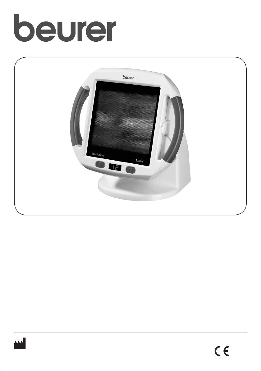
IL 50
D
Infrarot-Wärmestrahler
T
İnfrared radyan ısıtıcı
Gebrauchsanweisung ............... 2 – 7
Kullanma Talimatı ................. 29 – 34
G
Infrared heat lamp
r
Прибор инфракрасного
Instruction for Use ...................8 –12
излучения
Инструкция по
F
Radiateur thermique infrarouge
применению ......................... 34 – 40
Mode d’emploi .......................13 –18
Q
Promiennik podczerwieni
E
Radiador de calor infrarrojo
Instrukcja obsługi ................. 41 – 45
Instrucciones para el uso ..... 19 – 24
I
Radiatore a raggi infrarossi
ELECTROMAGNETIC COMPATIBILITY
INFORMATION .................................
46 – 48
Instruzioni per l’uso .............. 24 – 29
Beurer GmbH • Söflinger Str. 218 • 89077 Ulm, Germany
Tel.: +49 (0)731 / 39 89 -144 • Fax: +49 (0)731 / 39 89 - 255
www.beurer.com • Mail: kd@beurer.de
0483
DEUTSCH
auch bei Kochfeldern eingesetzt und sorgen in Zusam-
Inhalt
menhang mit dem Leuchtmittel für eine intensive und
1. Zum Kennenlernen ................................................2
sichere Infrarotbestrahlung mit 100 % UV-Schutz.
2. Zeichenerklärung ...................................................2
Außerdem ist das Gerät mit einer Stromsparfunktion
3. Sicherheitshinweise ............................................... 2
ausgestattet. Das bedeutet, wenn der Netzschalter
4. Gerätebeschreibung ..............................................4
ausgeschaltet ist, entsteht kein Stromverbrauch.
5. Bedienen ..............................................................5
6. Reinigen, Infrarotstrahler auswechseln und
aufbewahren ..........................................................5
2. Zeichenerklärung
7. Technische Angaben .............................................6
Folgende Symbole werden in der Gebrauchsanweisung
8. Entsorgen ..............................................................7
verwendet:
9. Garantie und Service .............................................7
Warnung Warnhinweis auf Verletzungs-
gefahren oder Gefahren für Ihre
Lieferumfang
Gesundheit.
•
Infrarot-Wärmestrahler
•
Diese Gebrauchsanweisung
Achtung Sicherheitshinweis auf mögliche
Schäden am Gerät/Zubehör.
1. Zum Kennenlernen
Hinweis Hinweis auf wichtige Informatio-
Sehr geehrte Kundin, sehr geehrter Kunde,
nen.
wir freuen uns, dass Sie sich für ein Produkt unseres
Infrarotstrahlung
Sortimentes entschieden haben.
Unser Name steht für hochwertige und eingehend ge-
Achtung, heiße Oberfläche
prüfte Qualitätsprodukte aus den Bereichen Wärme,
Gewicht, Blutdruck, Körpertemperatur, Puls, Sanfte
Therapie, Massage und Luft.
> 30 cm
Abstand
Bitte lesen Sie diese Gebrauchsanweisung aufmerk-
sam durch, bewahren Sie sie für späteren Gebrauch
auf, machen Sie sie anderen Benutzern zugänglich und
Folgende Symbole werden auf dem Typenschild ver-
beachten Sie die Hinweise.
wendet:
Mit freundlicher Empfehlung
Schutzisoliert Klasse 2
Ihr Beurer-Team
Anwendung
Gebrauchsanweisung beachten
Dieser Infrarot-Wärmestrahler ist nur für die Bestrah-
lung des menschlichen Körpers vorgesehen.
Vor Nässe schützen
Durch Bestrahlung mit Infrarotlicht wird Wärme an
den Menschen transportiert. Die bestrahlte Haut wird
verstärkt durchblutet und der Stoffwechselumsatz im
3. Sicherheitshinweise
Temperaturfeld erhöht. Der Körper wird durch die Wir-
Elektrische Sicherheit
kungsweise des Infrarotlichts zur Heilung angeregt;
Das Gerät wird durch eine automatisch auslösende
Heilprozesse können gezielt unterstützt werden.
Thermosicherung gegen Überhitzen geschützt.
Infrarotlicht kann z.B. eingesetzt werden als beglei-
tende Therapie bei der Behandlung von Hals-Nasen-
Warnung
Ohrenerkrankungen sowie zur Unterstützung der
Gesichts- und Schönheitspflege, insbesondere bei
•
Jeder unsachgemäße Gebrauch kann gefährlich
unreiner Haut. Des Weiteren kann die IR-Wärme unter-
sein!
stützend bei der Behandlung von Muskelverspannun-
•
Das Gerät darf nur an die auf dem Typschild ange-
gen und Erkältungen eingesetzt werden, da die Durch-
gebene Netzspannung angeschlossen werden.
blutung aufgrund der Wärme angeregt wird. Fragen
•
Verwenden Sie einen leicht zugänglichen Netzan-
Sie aber zunächst Ihren Hausarzt, ob die Anwendung
schluss, um im Bedarfsfall schnell den Netzstecker
im Einzelfall medizinisch sinnvoll ist. Das Gerät ist mit
ziehen zu können.
einer hochwertigen Keramik-Glasscheibe „Ceramic
•
Netzstecker nicht mit nassen Händen anfassen, Ge-
Infrared“ ausgestattet. Keramik-Glasscheiben werden
fahr eines elektrischen Schlages!
2
•
Verlegen Sie das Netzkabel so, dass niemand darü-
Sicherheitshinweise für Ihre Gesundheit
ber stolpern kann.
Warnung
•
Ziehen Sie stets den Netzstecker aus der Steckdo-
se, wenn Sie das Gerät nicht benutzen, das Gerät
•
Verbrennungsgefahr! Die Filterscheibe und das Ge-
reinigen oder bei Störungen, Rauch und Geruchs-
häuse des Gerätes erwärmen sich stark im Betrieb.
bildung. Beim Herausziehen des Netzsteckers am
Beim Berühren besteht Verbrennungsgefahr!
Netzstecker ziehen – nicht am Kabel!
•
Beim Bedienen der Tasten (Ein/Aus und Timer) nicht
•
Vor dem Gebrauch sicherstellen, dass das Gerät und
die heiße Scheibe berühren. Hier besteht Verbren-
Zubehör keine sichtbaren Schäden aufweisen. Be-
nungsgefahr.
nutzen Sie es im Zweifelsfall nicht und wenden Sie
•
Das Gerät vor dem Berühren immer erst abkühlen
sich an Ihren Händler oder an die angegebene Kun-
lassen.
dendienstadresse. Dies gilt insbesondere für Kratzer
•
Ziehen Sie stets den Netzstecker und lassen Sie das
und Risse in der Scheibe oder Risse am Gehäuse.
Gerät abkühlen, ehe Sie es wieder verpacken.
•
Bei Beschädigungen der Netzleitung und des Ge-
•
Das Gerät darf im angeschlossenen Zustand nicht
häuses wenden Sie sich an den Kundenservice oder
mit feuchten Händen angefasst werden.
Händler, da bei Nichtbeachten die Gefahr eines elek-
•
Es darf kein Wasser auf das Gerät spritzen.
trischen Schlages besteht.
•
Das Gerät darf nur im vollständig trockenen Zustand
•
Die Trennung vom Versorgungsnetz ist nur gewähr-
betrieben werden.
leistet, wenn der Netzstecker aus der Steckdose
•
Bei der Bestrahlung des Gesichts nicht direkt in das
gezogen ist.
Infrarotlicht blicken und die Augen schließen oder
bedecken.
Bestimmungsgemäßer Gebrauch
Das Gerät ist nur zum Bestrahlen des menschlichen
Wann soll das Gerät nicht verwendet werden?
Körpers vorgesehen. Jede andere Verwendung gilt als
Warnung
nicht bestimmungsgemäßer Gebrauch.
Um gesundheitlichen Schäden vorzubeugen ist in
Dieses Gerät ist nicht für den gewerblichen Gebrauch
folgenden Fällen von der Anwendung des Gerätes
bestimmt, sondern ausschließlich zur Verwendung im
dringend abzuraten:
privaten Haushalt!
•
Bei wärmeunempfindlichen Personen.
Sicherer Umgang
Das Wärmeempfinden kann in den folgenden Fällen
•
Dieses Gerät ist nicht dafür bestimmt, durch Per-
eingeschränkt oder erhöht sein:
sonen (einschließlich Kinder) mit eingeschränkten
•
bei diabetischen Patienten,
physischen, sensorischen oder geistigen Fähigkeiten
•
bei Personen mit Schläfrigkeit, Demenz oder Kon-
oder mangels Erfahrung und/oder mangels Wissen
zentrationsstörungen,
benutzt zu werden, es sei denn, sie werden durch ei-
•
bei Personen mit krankheitsbedingten Hautverände-
ne für ihre Sicherheit zuständige Person beaufsichtigt
rungen,
oder erhielten von ihr Anweisungen, wie das Gerät
•
bei Personen mit vernarbten Hautarealen im Anwen-
zu benutzen ist.
dungsgebiet,
•
Halten Sie Kinder vom Verpackungsmaterial fern
•
bei Personen mit Allergien,
(Erstickungsgefahr).
•
bei Kindern und älteren Personen,
•
Verwenden Sie das Gerät nie in der Nähe von Was-
•
nach der Einnahme von Medikamenten oder Alkohol.
ser.
Bei akut entzündlichen Prozessen sollte eine Bestrah-
•
Wenn das Gerät heruntergefallen ist oder extremer
lung erst nach Rücksprache mit einem Arzt durchge-
Feuchtigkeit ausgesetzt war oder anderweitige Schä-
führt werden.
den davongetragen hat, darf es nicht mehr benutzt
werden.
Wichtige Hinweise
•
Das Gerät darf nicht in Wasser oder Flüssigkeiten
Warnung
getaucht werden und es darf keine Flüssigkeit in das
Gerät eindringen.
•
Grundsätzlich richtet sich der Abstand zum Infrarot-
•
Lassen Sie das Gerät während des Betriebes nicht
Wärmestrahler nach der individuellen Wärmeemp-
unbeaufsichtigt.
findlichkeit und der jeweiligen Behandlung. Achten
•
Schalten Sie das Gerät sofort aus, wenn es defekt
Sie darauf, dass der Abstand von 30 cm zwischen
ist oder Betriebsstörungen vorliegen.
Infrarot-Wärmestrahler und dem bestrahlten Körper-
teil nicht unterschritten wird!
3
•
Begrenzen Sie stets die Anwendungsdauer und kon-
den Sie sich an Ihren Händler oder an die angege-
trollieren Sie die Reaktion der Haut.
bene Kundendienstadresse.
•
Medikamente, Kosmetika oder Nahrungsmittel kön-
•
Der Hersteller haftet nicht für Schäden, die durch
nen unter Umständen zu einer überempfindlichen
unsachgemäßen oder falschen Gebrauch verursacht
oder allergischen Reaktion der Haut führen. Die Be-
wurden.
strahlung ist in diesem Fall umgehend zu beenden.
•
Schützen Sie das Gerät vor Staub, Schmutz und
•
Bei Dauerbetrieb des Gerätes ist besondere Vorsicht
Feuchtigkeit.
und Aufmerksamkeit geboten.
Reparatur
•
Verwenden Sie das Gerät nicht, wenn Sie müde sind
und die Gefahr besteht, dass Sie während der Be-
Warnung
strahlung einschlafen!
Gefahr eines elektrischen Stromschlags!
•
Eine zu lange Bestrahlung kann gegebenenfalls zu
•
Sie dürfen das Gerät lediglich zum Leuchtmittel-
Hautverbrennung führen.
wechsel öffnen. Das Gerät bitte keinesfalls reparie-
•
Kinder erkennen die Gefahren, die in Verbindung mit
ren, da sonst eine einwandfreie Funktion nicht mehr
Elektrogeräten entstehen, nicht. Sorgen Sie dafür,
gewährleistet ist. Bei Nichtbeachten erlischt die Ga-
dass das Gerät nicht unbeaufsichtigt von Kindern
rantie.
benützt werden kann.
•
Wenden Sie sich bei Reparaturen an den Kunden-
Aufstellen
service oder an einen autorisierten Händler.
Achtung
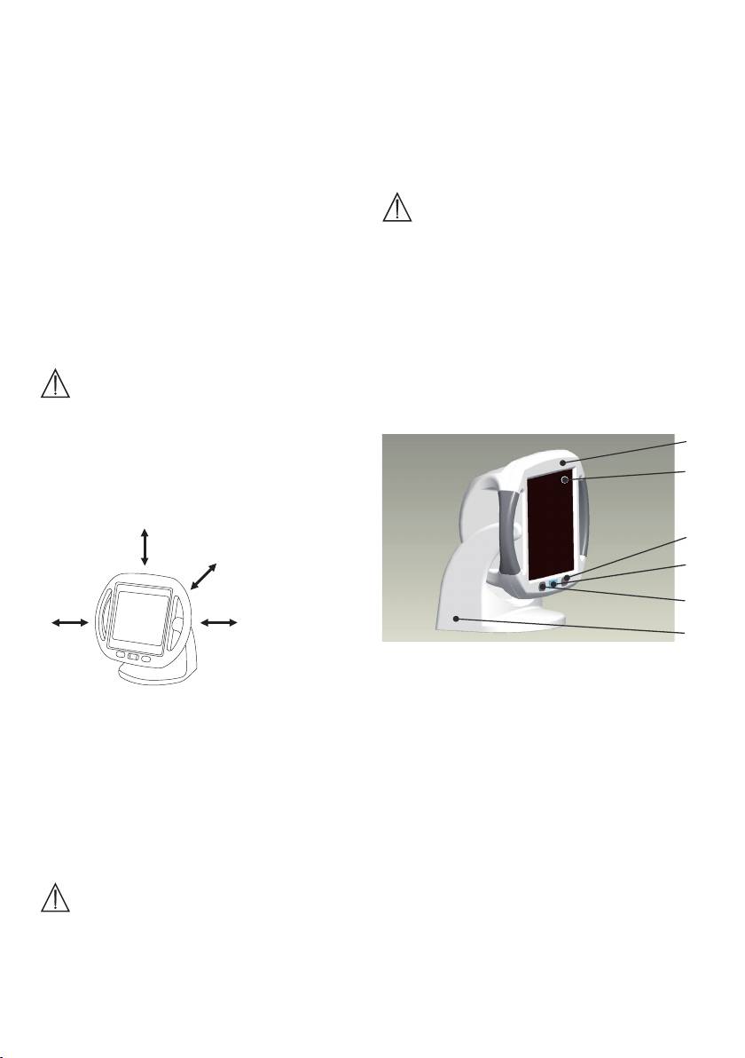
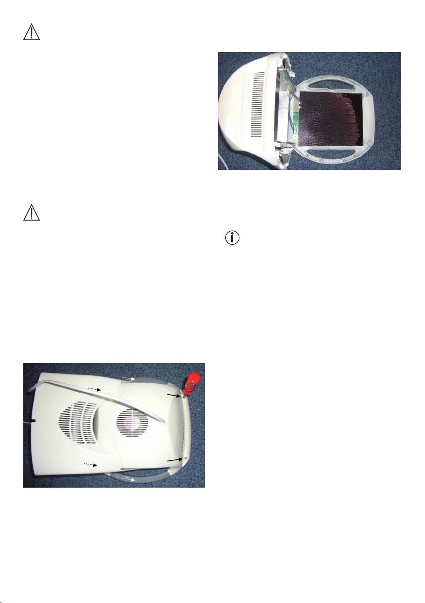
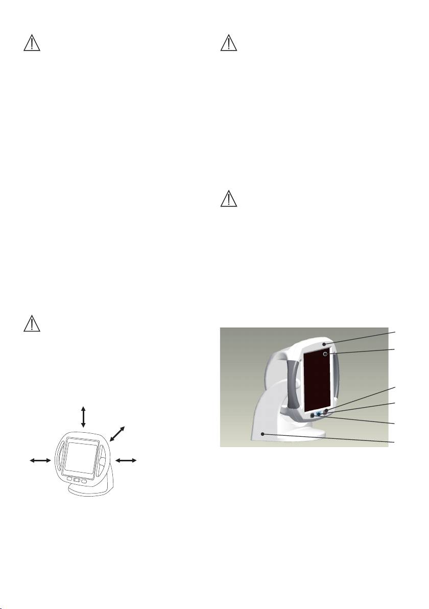
4. Gerätebeschreibung
•
Stellen Sie das Gerät auf eine feste und ebene Ar-
Übersicht
beitsfläche.
1
•
Das Gerät darf nicht gelegt oder schräg aufgestellt
werden.
•
Der Mindestabstand zwischen brennbaren Gegen-
ständen und dem Infrarotstrahler darf 1 Meter nicht
unterschreiten.
min. 1 m
Pos. Bezeichnung
1
Schwenkbares Gehäuse mit Handgriffen
•
Achten Sie bitte darauf, dass das Gerät nicht auf
2
Scheibe
brennbaren Gegenständen, wie z.B. Tischdecken
3
Ein-/Ausschalter
oder Teppichböden, steht.
4
Restzeitanzeige
•
Bringen Sie keine leicht entzündlichen oder schmel-
5
Zeitwahltaste
zenden Gegenstände in die Nähe des Gerätes.
6
Gerätefuß mit integriertem Kabelschacht zum
•
Hängen Sie das Gerät nicht an die Wand oder an die
Aufwickeln des Netzanschlusskabels.
Decke.
Infrarot-Wärmestrahler mit einstellbarem Timer (1
•
Benützen Sie das Gerät nicht im Freien.
bis 15 Minuten) und schwenkbarem Gehäuse (0 bis
•
Schützen Sie das Gerät vor stärkeren Stößen.
50 Grad).
Vor der Inbetriebnahme
•
Der Timer schaltet das Gerät nach Ablauf der einge-
stellten Zeit automatisch ab.
Achtung
•
Das schwenkbare Gehäuse ermöglicht eine indivi-
•
Vor Gebrauch des Gerätes ist jegliches Verpackungs-
duelle Einstellung des Infrarot-Wärmestrahlers.
material zu entfernen.
•
Überprüfen Sie das Gerät auf Anzeichen von Abnut-
zung oder Beschädigung. Benutzen Sie das Gerät
bei Beschädigungen im Zweifelsfall nicht und wen-
4
2
3
4
5
6
Zu Beginn empfehlen wir eine kürzere Bestrahlungs-
5. Bedienen
dauer zu wählen. Die Haut einzelner Menschen kann
Auspacken und auf stellen
jedoch auch bei korrekter Anwendung des Gerätes auf
Warnung
die Wärmebestrahlung überempfindlich (z. B. starke
Rötung, Blasenbildung, Juckreiz, starkes Schwitzen)
•
Entfernen Sie vor Gebrauch des Gerätes alle Verpa-
oder allergisch reagieren.
ckungsmaterialien.
•
Wickeln Sie das Netzanschlusskabel vollständig ab.
Gerät starten
•
Stellen Sie das Gerät auf eine stabile, ebene Unter-
Achtung
lage.
•
Halten Sie einen Abstand von mindestens 1 Meter
•
Schließen/bedecken Sie bei der Bestrahlung des
zu anderen Gegenständen, um das Gerät selbst vor
Gesichtes stets die Augen!
Überhitzung zu schützen und die Gefahr eines Bran-
•
Drücken Sie den Ein-/Ausschalter (3).
des/Feuers zu vermeiden.
•
Das Gerät schaltet sich nach kurzer Zeit selbststän-
•
Hängen Sie das Gerät nicht an die Wand oder an die
dig ein.
Decke.
•
Drücken Sie auf die Zeitwahltaste (5) um die ge-
•
Stecken Sie den Netzstecker in die Steckdose.
wünschte Behandlungsdauer einzustellen (1 bis
•
Schalten Sie das Gerät am Ein-/Ausschalter (3) ein.
15 Minuten).
Die Restzeitanzeige (4) zeigt 15 Minuten an.
•
Wird während des Betriebs die Zeitwahltaste (5)
gedrückt, kann die Behandlungsdauer individuell
Achtung
nachgestellt werden.
•
Nach Ablauf der eingestellten Zeit wird der Wärme-
•
Vermeiden Sie Stöße während des Betriebes und
strahler automatisch abgeschaltet.
der Abkühlphase da diese zur Beschädigung des
•
Bei einer weiteren Behandlung müssen Sie lediglich
Leuchtmittels führen können.
die Zeitwahltaste (5) betätigen um Ihre individuelle
•
Stellen Sie die gewünschte Behandlungszeit (1 bis
Behandlungszeit wieder einzustellen.
15 Minuten) durch mehrmaliges Drücken der Zeit-
wahltaste (5).
Achtung
•
Die eingestellte Zeit wird in der Restzeitanzeige (4)
angezeigt.
•
Hierbei nicht die heiße Scheibe berühren.
•
Wenn Sie die Behandlung beenden wollen schalten
Behandlung vorbereiten
Sie das Gerät erst am Ein/-Ausschalter (3) aus und
•
Platzieren Sie sich so vor dem Gerät, dass Sie die
ziehen Sie danach den Netzstecker.
Behandlung des betroffenen Körperteils entspannt
genießen können.
Während der Behandlung
•
Stellen Sie durch Neigen der Infrarotlampe die op-
•
Kontrollieren Sie regelmäßig die bestrahlte Körper-
timale Ausrichtung des Geräts zum behandelnden
stelle und die Reaktion der Haut. Beenden Sie bei
Körperteil ein.
Anzeichen von Überempfindlichkeit oder allergischer
•
Grundsätzlich richtet sich der Abstand zum Wärme-
Reaktion umgehend die Bestrahlung und konsultie-
strahler nach der individuellen Wärmeempfindlichkeit
ren Sie einen Arzt.
und der jeweiligen Behandlung.
•
Das Gerät kann jederzeit durch Drücken des Ein-/
•
Achten Sie darauf, dass der Abstand von 30 cm
Ausschalters (3) ausgeschaltet werden.
zwischen Wärmestrahler und dem bestrahlten
•
Das Gerät darf im erwärmten Zustand nicht ab- oder
Körperteil nicht unterschritten wird.
zugedeckt oder verpackt aufbewahrt werden.
Benutzen Sie das Gerät nicht fortlaufend länger als
Nach der Behandlung
15 Minuten, Überhitzungsgefahr! Lassen Sie das Gerät
•
Schalten Sie das Gerät am Ein-/Ausschalter (3) aus.
erst abkühlen bevor Sie es wieder benützen.
•
Ziehen Sie den Netzstecker aus der Steckdose.
Behandlungsdauer
6. Reinigen, Infrarotstrahler aus-
Achtung
wechseln und aufbewahren
•
Gefahr von Verbrennungen: Entfernen Sie metal-
Reinigen
lische Teile, wie z.B. Gürtelschnallen, Halsbänder,
BHs, Schmuck oder Piercings, vor dem Einschalten
Achtung
des Gerätes aus der Behandlungszone, da sich diese
Vor jeder Reinigung muss das Gerät ausgeschaltet,
stark erhitzen können.
vom Netz getrennt und vollständig abgekühlt sein.
5
3
. Das Gehäuse aufstellen, dabei das vordere Teil mit
Achtung
der Keramik-Glasscheibe auf der Unterlage liegen
•
Achten Sie darauf, dass kein Wasser in das Geräte-
lassen.
innere gelangt!
•
Gerät nicht in der Spülmaschine reinigen!
Das Gerät kann mit einem feuchten Tuch gereinigt
werden. Verwenden Sie keine lösungsmittelhaltigen
Reinigungsmittel.
Infrarotstrahler auswechseln
Bitte beachten Sie, dass als Ersatz für ein defektes
Leuchtmittel nur ein Leuchtmittel des gleichen Typs
verwendet werden darf.
Ersatzstrahler
Typ: Halogenleuchtmittel 220 – 240 V / 300 W
4
. Fassen Sie das abgekühlte Leuchtmittel am linken
118 mm Länge für Sockel R7S
bzw. rechten Ende an und drücken Sie es vorsichtig
Original Best-Nr.: 162.620
nach rechts bzw. links.
5
. Ziehen Sie jetzt das Leuchtmittel nach vorne aus
Warnung
der Fassung.
Gefahr eines elektrischen Stromschlags!
•
Vor dem Auswechseln des Leuchtmittels das Netz-
Hinweis
anschlusskabel aus der Steckdose ziehen!
Neue Lampe nur mit einem Tuch einsetzen, nicht mit
•
Verbrennungsgefahr an heißen Oberflächen!
den bloßen Fingern anfassen, da die Fettschicht auf
•
Vor dem Beginn der Reparatur das Gerät vollständig
der Haut die Lampe beschädigen kann.
abkühlen lassen!
6
. Setzen Sie das neue Leuchtmittel in die Fassung ein.
•
Leuchtmittel sind von der Garantie ausgenommen.
Das Einsetzen des neuen Leuchtmittels erfolgt sinn-
Vorgehensweise
gemäß in umgekehrter Reihenfolge wie der Ausbau.
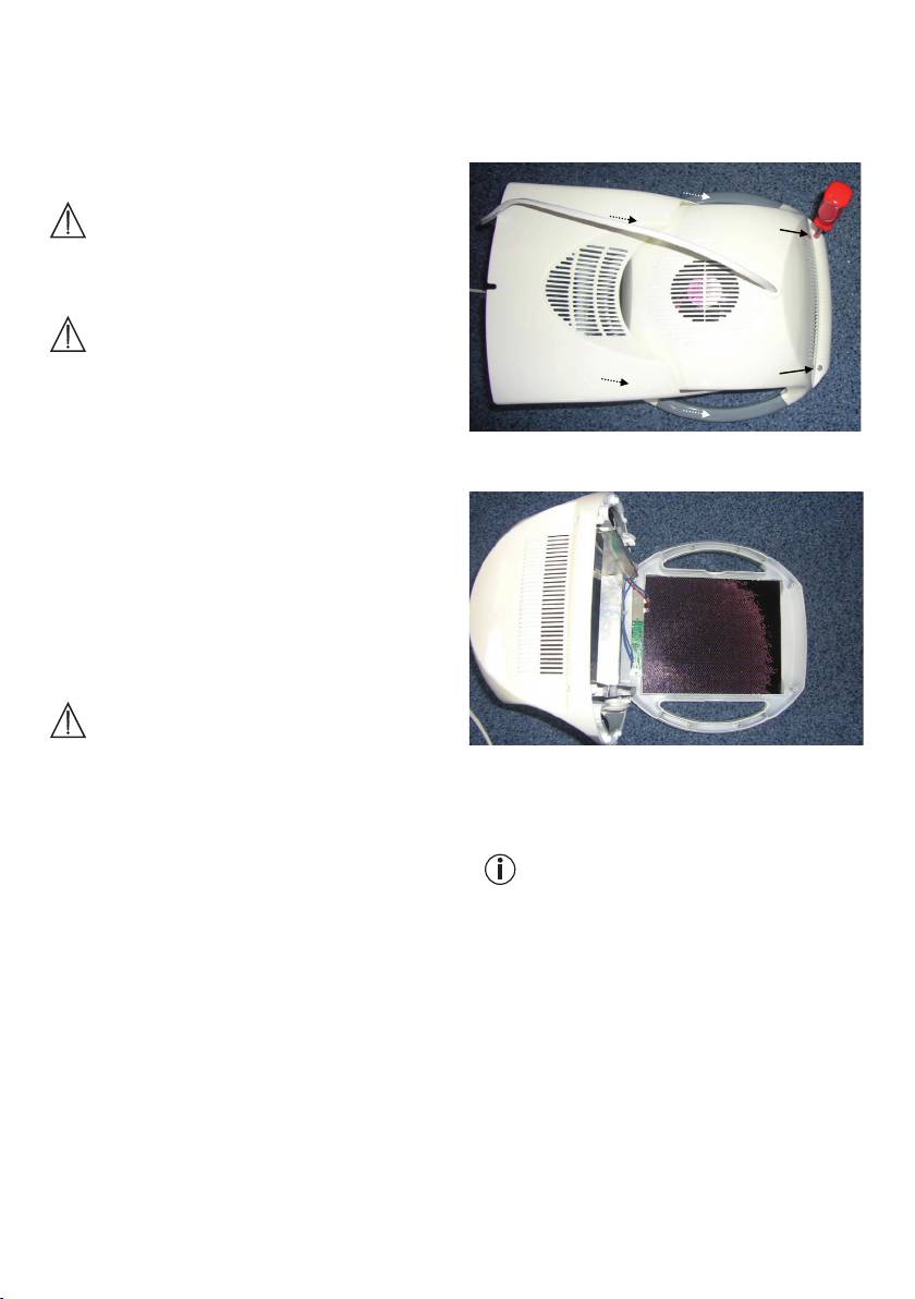
1
. Das abgekühlte Gerät mit der Ceramic Glasscheibe
7
. Schließen Sie das Gerät wieder. Das Schließen des
auf eine ebene Unterlage legen.
Geräts erfolgt sinngemäß in umgekehrter Reihenfol-
2
. Mit einem passenden Kreuzschlitz-Schraubendreher
ge wie das Öffnen.
die sechs Schrauben in der Geräterückwand her-
Achten Sie darauf, dass keine Gegenstände im
ausdrehen.
Gehäuse verbleiben und keine Kabel eingeklemmt
werden!
Aufbewahren
Ziehen Sie den Netzstecker und lassen Sie das Gerät
vollständig abkühlen, bevor Sie es bewegen.
Bewahren Sie den Wärmestrahler am besten in der
Original-Verpackung an einem trockenen Ort auf.
7. Technische Angaben
Netzanschluss AC 220 V – 240 V / 50 – 60 Hz
Leistungs-
aufnahme 300 W
Timer Einstellbar von 1 bis 15 Minuten in
Minutenschritten
Abmessungen
(BxHxT) 270 x 285 x 195 mm
Gewicht Cirka 1,6 kg
Betriebs-
Temperatur: 10 °C bis 35 °C
bedingungen
Relative Luftfeuchte: ≤ 90 %
6
ger Straße 218, 89077 Ulm, Deutschland, geltend zu
Lager- und
machen.
Transport-
Temperatur: -10 °C bis 50 °C
Der Kunde hat im Garantiefall das Recht zur Reparatur
bedingungen
Relative Luftfeuchte: ≤ 90 %
der Ware bei unserem eigenen oder bei von uns auto-
Schutzklasse II
risierten Werkstätten. Weitergehende Rechte werden
Bestrahlungs-
dem Kunden (aufgrund der Garantie) nicht eingeräumt.
stärke Max. 200 mW/qm
IR-Type A + B
Technische Änderungen zur Verbesserung und Wei-
terentwicklung des Produktes behalten wir uns vor.
Farbabweichungen der Scheibe im Betrieb sind pro-
duktionstechnisch bedingt und haben keinerlei Auswir-
kung auf die Wirkungsweise und Qualität.
8. Entsorgen
Im Interesse des Umweltschutzes darf die Infrarotlam-
pe am Ende ihrer Lebensdauer nicht mit dem Hausmüll
entfernt werden. Die Entsorgung kann über entspre-
chende Sammelstellen in Ihrem Land erfolgen.
Befolgen Sie die örtlichen Vorschriften bei der Entsor-
gung der Materialien.
Entsorgen Sie das Gerät gemäß der Elekt-
ro- und Elektronik-Altgeräte-EG-Richtlinie
2002/96/EC – WEEE (Waste Electrical and
Electronic Equipment). Bei Rückfragen wenden Sie
sich an die für die Entsorgung zuständige kommunale
Behörde.
Dieses Gerät entspricht der europäischen Norm
EN60601-1-2 und unterliegt besonderen Vorsichts-
maßnahmen hinsichtlich der elektromagnetischen
Verträglichkeit. Bitte beachten Sie dabei, dass tragbare
und mobile HF-Kommunikationseinrichtungen dieses
Gerät beeinflussen können. Genauere Angaben können
Sie unter der angegebenen Kundenservice-Adresse
anfordern oder am Ende der Gebrauchsanweisung
nachlesen.
9. Garantie und Service
Sie erhalten 3 Jahre Garantie ab Kaufdatum auf Mate-
rial- und Fabrikationsfehler des Produktes.
D
ie Garantie gilt nicht:
•
im Falle von Schäden, die auf unsachgemäßer Be-
dienung beruhen,
•
für Verschleißteile (z.B. Leuchtmittel),
•
für Mängel, die dem Kunden bereits beim Kauf be-
kannt waren,
•
bei Eigenverschulden des Kunden.
Die gesetzlichen Gewährleistungen des Kunden blei-
ben durch die Garantie unberührt. Für Geltendmachung
eines Garantiefalles innerhalb der Garantiezeit ist durch
den Kunden der Nachweis des Kaufes zu führen. Die
Garantie ist innerhalb eines Zeitraumes von 3 Jahren
ab Kaufdatum gegenüber der Beurer GmbH, Söflin-
7
ENGLISH
Contents
2. Signs and symbols
1. Welcome ................................................................8
The following symbols appear in these instructions:
2. Signs and symbols ................................................8
Warning instruction indicating a
Warning
3. Safety notes...........................................................8
risk of injury or damage to health.
4. Unit description ...................................................10
Safety note indicating possible
5. Operation .............................................................10
Important
damage to the unit/accessory.
6. Cleaning, changing the infrared lamp
and storage..........................................................11
Note Note on important information.
7. Technical specifications ......................................12
8. Disposal ............................................................... 12
Infrared radiation
Included in delivery
Caution: hot surface
•
Infrared radiant heater
•
These operating instructions
> 30 cm
Distance
1. Welcome
Dear customer,
The following symbols are used on the type plate:
thank you for choosing one of our products.
Protective insulation class 2
Our name stands for high-quality, thoroughly tested
products for applications in the areas of heat, weight,
blood pressure, body temperature, pulse, gentle th
Observe the instructions for use
rapy, massage and air.
Please read these instructions carefully and keep them
Protect from moisture
for later use. Be sure to make them accessible to other
users and observe the information they contain.
3. Safety notes
With kind regards
Your Beurer team.
Electrical safety
The unit is protected against overheating by an auto-
Use
matic thermal cut-out.
This infrared radiant heater is only intended for radiat-
ing the human body.
Warning
Infrared light causes warmth to be transported to the
•
Improper use can be dangerous!
human body. Blood supply to the radiated skin is im-
•
Connect the unit only to the mains voltage listed on
proved and the metabolic rate is increased in the field
the type plate.
of temperature. The body is stimulated to heal by the
•
Use an easily accessible mains connection so you
effect of the infrared light; healing processes are tar-
can disconnect the plug quickly in an emergency.
geted specifically.
•
Do not touch the plug with wet hands - risk of electric
Infrared light can, for example, be used as an accom-
shock!
panying therapy in the treatment of ear, nose and throat
•
Lay the mains cable in such a way that no one can
diseases, as well as in facial and beauty care, especial-
trip over it.
ly with impure skin. IR heat can also be used as a sup-
•
Always remove the mains plug from the socket when
port tool in the treatment of muscle tension and chills
the unit is not being used, when cleaning it or in the
because the heat stimulates blood flow. You should
event of a malfunction, smoke or unusual smell. Do
first ask your GP whether its use is medically advisable
not pull on the cable to remove the plug from the
in particular cases. The unit has a high-quality glass
socket.
ceramic plate (ceramic infrared). Glass ceramic plates
•
Before use, make sure the unit and accessories do
are also used on hobs and when used in conjunction
not have any visible damage. If in doubt, do not use
with a lamp ensure intensive and safe infrared radiation
the unit and contact your dealer or the customer
that is 100% safe. The device is also equipped with an
service address provided. This applies especially to
energy saving function, which means that no power is
scratches and cracks in the glass or cracks in the
used when the mains switch is switched off.
housing.
8
•
Contact Customer Service or your dealer if the cord
Heat sensitivity can be reduced or increased in the
or housing are damaged, otherwise you risk an elec-
following cases:
tric shock.
•
in diabetic patients,
•
Disconnection from the mains supply is only guar-
•
in people suffering from drowsiness, dementia or a
anteed if the mains plug has been removed from the
lack of concentration,
socket.
•
in people with skin changes caused by illness,
•
in people with scarred skin in the treatment area,
Proper use
•
in people with allergies,
The unit is intended for directing infrared radiation at
•
in children and elderly people,
the human body. Any other use is regarded as im-
•
after taking medicine or consuming alcohol.
proper. This unit is not designed for commercial use,
In cases of acute inflammatory processes, the unit
but for use in the private home!
should only be used after consultation with a doctor.
Safe handling
Important notes
•
This unit is not intended for use by persons (including
children) of limited physical or mental abilities or insuf-
Warning
ficient experience or knowledge, unless their safety
•
The distance to the infrared radiant heater depends
is supervised by a responsible person or they have
largely on personal heat sensitivity and the treat-
been instructed in use of the unit by that person.
ment concerned. Make sure the distance between
•
Keep children away from packaging materials (risk
the infrared radiant heater and the body part being
of suffocation).
treated is not less than 30 cm!
•
Never use the unit near water.
•
Always limit the length of use and check for skin
•
The unit should not be used if it has been dropped,
reactions.
exposed to extreme humidity or damaged in any
•
Under some circumstances, medicines, cosmetics
other way.
and foodstuffs can lead to oversensitive or allergic
•
Do not immerse the unit in water or other liquids and
skin reactions. Treatment should be discontinued
do not allow liquids to enter the unit.
immediately in these cases.
•
Do not leave the unit unsupervised during operation.
•
Special care and caution is necessary if using the
•
Switch the unit off immediately if it becomes faulty
unit for a long period.
or malfunctions.
•
Do not use the unit if there is the risk of your falling
Safety advice for your health
asleep!
•
Excessive exposure can result in skin burns.
Warning
•
Children do not understand the risks associated with
•
Risk of burns! The filter disc and unit housing be-
electrical appliances. Make sure that the unit cannot
come very hot during operation. You could be burnt
be used unsupervised by children.
by touching it!
•
Do not touch the hot glass when operating the but-
tons (On/Off and timer). There is a risk of burning.
•
Always allow the unit to cool down before you touch
it.
•
Always remove the mains plug and let the unit cool
down before you pack it away.
•
Do not touch the unit with wet hands if it is plugged
in.
•
Do not allow water to spray on the unit.
•
The unit must be operated only when it is completely
dry.
•
When directing the unit at the face, do not look di-
rectly at the infrared light; close or cover the eyes.
When should the unit not be used?
Warning
It is strongly recommended not to use the unit in the
following cases in order to prevent health injuries:
•
for person insensitive to heat.
9
S
et-up
4. Unit description
Important
Overview
1
•
Place the unit on a solid and even surface.
•
The unit must not be set up on a slope or laying
2
down.
•
The minimum distance between flammable items
and the infrared lamp must not be less than 1 metre.
3
4
min. 1 m
5
6
Item Name
1
Swivelling body with handles
•
Please make sure the unit is not placed on flammable
2
Disc
materials such as table cloths or carpets.
3
On/Off switch
•
Do not leave any easily flammable or meltable items
4
Remaining time display
close to the unit.
5
Time selector
•
Do not hang the unit on the wall or from the ceiling.
6
Foot with integrated cable channel for coiling the
•
Do not use the unit in the open air.
power cable.
•
Protect the unit from strong impacts.
Infrared radiant heater with adjustable timer (1 to 15
Before starting
minutes) and swivelling body (0 to 50 degrees).
•
The timer switches off automatically at the end of the
Important
set time.
•
Before you use the unit for the first time, remove all
•
The swivelling body allows you to adjust the infrared
packaging materials.
radiant heater to suit your needs.
•
Check the unit for signs of use or damage. If in doubt
and the unit is damaged, do not use it and contact
5. Operation
your dealer or the customer service address pro-
Unpacking and set-up
vided.
•
The manufacturer is not liable for damage caused by
Warning
improper or incorrect use.
•
Remove all packaging materials before using the
•
Protect the unit from dust, dirt and moisture.
unit.
•
Unwind the power cable fully.
Repairs
•
Place the unit on a solid and even surface.
Warning
•
Maintain a distance of at least 1 metre from other
Danger of an electric shock!
objects, both to protect the unit itself from overheat-
•
Open the unit only to change the lamp. Do not at-
ing and to prevent the risk of fire or burning.
tempt to repair the unit, otherwise problem-free op-
•
Do not hang the unit on the wall or from the ceiling.
eration cannot be guaranteed. Failure to observe this
•
Insert the mains plug in the socket.
condition will void the warranty.
•
Switch on the unit at the On/Off switch (3). The re-
•
For repairs, contact Customer Service or an author-
maining time display (4) shows 15 minutes.
ised dealer.
Warning
•
Do not bump the unit while it is operating or cooling
down or you could damage the lamp.
•
Set the desired treatment time (1 to 15 minutes) by
pressing the time selector (5) several times.
•
The set time will appear on the display (4).
10
Preparing for treatment
ately if there are any signs of oversensitivity or an
•
Arrange yourself in front of the unit so you can relax
allergic reaction, and consult a doctor.
and enjoy the treatment of the part of the body con-
•
The unit can be switched off at any time using the
cerned.
On/Off switch (3).
•
Tilt the lamp so the unit is angled directly at the part
•
Do not cover up or pack the unit away while it is
of the body being treated.
warm.
•
The distance to the infrared radiant heater depends
After treatment
largely on personal heat sensitivity and the treatment
•
Switch off the unit at the On/Off switch (3).
concerned.
•
Pull the mains plug out of the socket.
•
Make sure the distance between the infrared radi-
ant heater and the part of the body being treated
6. Cleaning, changing the infrared
is not less than 30 cm!
lamp and storage
Do not use the unit for more than 15 minutes at a time
(risk of overheating). Allow the unit to cool down before
Cleaning
you use it again.
Important
Treatment duration
Before cleaning the unit, switch it off, unplug it and
allow it to cool down completely.
Important
•
Risk of burns: Remove any metal items, e.g. belt
Important
buckles, necklaces, bras, jewellery or piercings, from
•
Ensure that no water enters the unit!
the treatment area before switching on the device as
•
Do not wash the unit in a dishwasher!
they can become very hot.
We recommend short treatment times at the beginning.
The unit can be cleaned with a damp cloth. Do not use
However, even when the unit is used correctly, the skin
cleaning agents.
of some people can have an oversensitive or allergic
Changing the infrared lamp
reaction to the heat treatment (e.g. intense redness,
Remember that a faulty lamp should only be replaced
blisters, itching, heavy sweating).
with a lamp of the same type.
Starting the unit
Replacement lamp
Important
Type: Halogen lamp 220 - 240V / 300 W
118 mm long for R7S socket
•
Always close or cover your eyes when radiating the
Original Order no. 162.620
face.
•
Press the On/Off switch (3)
Warning
•
The unit will turn on automatically after a short time.
Danger of an electric shock!
•
Set the time selector (5) to the desired duration (1 to
•
Before changing the lamp, make sure the power ca-
15 minutes).
ble is unplugged from the socket.
•
You can press the time selector (5) during operation
•
Risk of burning on hot surfaces!
to reset the treatment duration.
•
Allow the unit to cool completely before any repairs.
•
The infrared radiant heater switches off automatically
•
Lamps are not covered by the guarantee.
after the set time.
•
For an additional treatment, you only need to press
the time selector (5) to reset your individual treatment
time.
Important
•
Do not touch the hot glass.
•
To end treatment, use the On/Off switch (3) and dis-
connect the power plug.
During treatment
•
Examine the part of the body treated frequently and
check for skin reactions. Cease exposure immedi-
11

Procedure
7. Technical specifications
1
. Place the cool unit with the glass ceramic plate down
Mains connec-
on a flat surface.
tion AC 220 V – 240 V / 50 – 60 Hz
2
. Using a suitable crosshead screwdriver, undo the
Power con-
six screws in the back panel.
sumption 300 W
Timer Adjustable from 1 to 15 minutes in
one-minute steps.
Dimensions
(WxHxD) 270 x 285 x 195 mm
Weight Approx. 1.6 kg
Operating
Temperature: 10 °C to 35 °C
conditions
(-14 °F to 95 °F)
Relative humidity: ≤ 90 %
Storage and
Temperature: -10 °C to 50 °C
transport:
(-50 °F to 122 °F)
Relative humidity: ≤ 90 %
Protection
3
. Place the body so that the front ofthe glass ce-
class II
ramic plate is lying on the flat surface.
Radiation
intensity Max. 200 mW/sqm
IR type A + B
We retain the right to make technical modifications to
improve and further develop the product. For manufac-
turing reasons, the colour of the glass may change dur-
ing operation but this does not affect the performance
or quality of the unit.
8. Disposal
In the interests of environmental protection, the infrared
lamp should not be discarded with household rubbish
4
. Take the cool lamp by the left or right end and press
at the end of its service life. Dispose of the unit at a
it carefully to the right or left.
suitable local collection or recycling point. Follow the
5
. Now lift it forwards and out of the socket.
local regulations for disposal of materials.
Note
Dispose of the unit in accordance with the EC
Directive for waste electrical and electronic
Use a cloth to hold the new lamp when inserting it,
equipment 2002/96/EC – WEEE (Waste Elec-
not bare fingers, as the grease on your skin could
trical and Electronic Equipment). If you have
damage the coating on the lamp.
any questions, please contactz the local authorities
6
. Insert the new lamp in the socket. The new lamp is
responsible for waste disposal.
inserted in the reverse order to removal.
This equipment complies with European standard
7
. Close the unit again. The unit is closed in the reverse
EN 60601-1-2 and is subject to specific safety provi-
order to opening it.
sions for electromagnetic compatibility. Please note,
Make sure that no foreign objects are left in the
however, that portable and mobile HF communication
body of the unit and that nocables become trapped.
equipment may influence this unit. More details can be
requested from the stated Customer Service address
Storage
or found at the end of the instructions for use.
Remove the mains plug and let the unit cool down
completely before you move it.
If possible, store the infrared radiant heater in its origi-
nal packaging in a dry place.
12
FRANÇAIS
frared“. Les vitres en céramique sont également utilisées
Table des matières
pour les plaques de cuisson et assurent, en combinai-
1. Familiarisation avec l’appareil .............................13
son avec l’ampoule, un rayonnement infrarouge intensif
2. Symboles utilisés ................................................. 13
et sûr avec une protection de 100 % contre les UV.
3. Consignes de sécurité .........................................13
Par ailleurs, l’appareil est équipé d’une fonction d’éco-
4. Présentation de l’appareil ....................................15
nomie d’énergie. Autrement dit : lorsque l’interrupteur
5. Utilisation ............................................................ 16
d’alimentation est coupé, il n’y a aucune consomma-
6. Nettoyage, remplacement et conservation du
tion de courant.
radiateur infrarouge .............................................17
7. Caractéristiques techniques ................................18
8. Mise au rebut ....................................................... 18
2. Symboles utilisés
Les symboles suivants sont utilisés dans ce mode
Eléments fournis
d’emploi :
•
Radiateur thermique infrarouge
Avertisse-
Ce symbole vous avertit des
•
Le présent mode d’emploi
ment
risques de blessures ou des
dangers pour votre santé.
1. Familiarisation avec l’appareil
Attention Ce symbole vous avertit des
Cher cliente, cher client,
éventuels dommages au niveau
nous vous remercions d’avoir choisi l’un de nos pro-
de l’appareil ou d’un accessoire.
duits. Notre société est réputée pour l’excellence de
Remarque Ce symbole indique des informa-
ses produits et les contrôles de qualité approfondis
tions importantes.
auxquels ils sont soumis, dans les domaines suivants :
chaleur, contrôle du poids, diagnostic de pression arté-
Rayonnement infrarouge
rielle, mesure de température du corps et du pouls,
thérapies douces, massage et purification d’air.
Attention, surface chaude
Lisez attentivement ce mode d’emploi, conservez- le
pour un usage ultérieur, mettez-le à la disposition des
autres utilisateurs et suivez les consignes qui y figurent.
> 30 cm
Distance
Sincères salutations,
Votre équipe Beurer
Les symboles suivants sont utilisés sur la plaque signa-
Application
létique :
Ce radiateur infrarouge est uniquement prévu pour le
Double isolation classe 2
rayonnement sur le corps humain.
La chaleur est transmise sur l’homme par rayonnement
Respectez les consignes du mode
de lumière infrarouge. La peau soumise au rayonne-
d‘emploi
ment est fortement pénétrée et le métabolisme est
augmenté dans le champ de température. Le corps
Protéger contre l‘humidité
est stimulé à des fins de guérison par le mode d’action
de la lumière infrarouge ; les processus de guérison
peuvent être facilités de façon ciblée.
3. Consignes de sécurité
La lumière infrarouge peut par exemple être mise en
Sécurité électrique
oeuvre en tant que thérapie accompagnatrice lors du
traitement de maladies du cou, du nez et des oreilles,
L’appareil est protégé contre la surchauffe par l’inter-
ainsi que pour favoriser les soins du visage et les soins
médiaire d’un fusible thermique à déclenchement
de beauté, notamment en cas d’impuretés de la peau.
automatique.
En outre, la chaleur infrarouge peut être mise à contribu-
Avertissement
tion pour le traitement de contractures musculaires et de
refroidissements, étant donné que la circulation du sang
•
Toute utilisation inappropriée peut s’avérer dan-
est stimulée par la chaleur. Mais demandez tout d’abord
gereuse !
votre médecin traitant au cas par cas si l’application est
•
L’appareil doit uniquement être raccordé à la tension
recommandée sur le plan médical. L’appareil est pourvu
secteur indiquée sur la plaque signalétique.
d’une vitre en céramique de grande qualité „Ceramic In-
13
•
Utilisez une prise secteur facilement accessible, afin
•
Mettez immédiatement l’appareil hors tension en
de pouvoir débrancher la fiche secteur en cas de
cas de défaillance ou en présence de dysfonction-
besoin.
nements.
•
Ne touchez pas la fiche d’alimentation avec les
Consignes de sécurité pour votre santé
mains mouillées, risque d’électrocution !
•
Posez le câble d’alimentation de telle sorte que per-
Avertissement
sonne ne puisse trébucher.
•
Risques de brûlures ! Le disque filtrant et le boî-
•
Débranchez systématiquement la fiche secteur de
tier de l’appareil s’échauffent fortement pendant le
la prise de courant si vous n’utilisez pas l’appareil,
fonctionnement. En les touchant, il y a danger de
lorsque vous nettoyez l’appareil ou en cas de déran-
brûlures !
gements, de formation de fumée ou d’odeurs. En
•
Lors de l’utilisation des touches (marche/arrêt et tem-
débranchant la fiche secteur, tirez sur la fiche secteur
porisateur), ne touchez pas la vitre chaude. Danger
- pas sur le câble !
de brûlure !
•
Avant l’utilisation, assurez-vous que l’appareil et
•
Laissez tout d’abord refroidir systématiquement
les accessoires ne présentent pas de dommages
l’appareil avant de le toucher.
apparents. En cas de doute, n’utilisez pas l’appareil
•
Débranchez toujours la fiche secteur et laissez l’ap-
et adressez-vous à votre revendeur ou reportezvous
pareil refroidir avant de le réemballer.
à l’adresse du service après-vente indiquée. Ceci
•
L’appareil ne doit pas être saisi avec des mains
vaut en particulier pour les rayures et fissures dans
humides à l’état raccordé.
la vitre, ou les fissures sur le boîtier.
•
L’appareil ne doit pas être soumis aux projections
•
En cas d’endommagements du câble d’alimentation
d’eau.
et du boîtier, adressez-vous au service après-vente
•
L’appareil doit uniquement être utilisé à l’état entiè-
ou au revendeur ; en cas de non-observation, il y a
rement sec.
risque de choc électrique.
•
Lors du rayonnement sur le visage, ne pas regarder
•
La déconnexion du réseau d’alimentation n’est ga-
directement dans la lumière infrarouge et fermer les
rantie que si la fiche secteur est débranchée de la
yeux ou les recouvrir.
prise de courant.
Quand l’appareil ne doit-il pas être utilisé ?
Utilisation conforme aux prescriptions
L’appareil est uniquement prévu pour le rayonnement
Avertissement
sur le corps humain. Toute autre utilisation est consi-
Afin d’éviter des dommages corporels, l’utilisation
dérée comme étant non conforme.
de l’appareil est fortement déconseillé dans les cas
Cet appareil n’est pas destiné à une utilisation indus-
suivants :
trielle, mais exclusivement à une utilisation domestique
•
Pour les personnes insensibles à la chaleur.
privée !
La sensation de chaleur peut être limitée ou augmentée
Manipulation sans danger
dans les cas suivants :
•
Cet appareil n’est pas destiné pour une utilisation
•
pour les patients diabétiques,
par des personnes (y compris des enfants) avec des
•
pour les personnes en somnolence, présentant des
facultés physiques, sensorielles ou intellectuelles
signes de démence ou des problèmes de concen-
limitéesou manquant d’expérience et/ou de connais-
tration,
sances, sauf si elles sont sous la surveillance d’une
•
pour les personnes avec modifications de la peau
personne compétente pour leur sécurité ou s’ils ont
dues à des maladies,
reçu l’autorisation de cette personne pour utiliser
•
pour les personnes avec des cicatrices dans le
l’appareil.
champ d’application,
•
Tenez éloignés les enfants du matériel d’emballage
•
pour les personnes présentant des allergies,
(danger d’étouffement).
•
pour les enfants et les personnes âgées,
•
N’utilisez en aucun cas l’appareil à proximité de l’eau.
•
après la prise de médicaments ou d’alcool.
•
Si l’appareil est tombé ou s’il a été exposé à une
Dans le cas de processus inflammatoires aiguës,
humidité extrême ou s’il a subi d’autres dommages,
un rayonnement devrait uniquement avoir lieu après
il ne doit plus être utilisé.
consultation avec un médecin.
•
L’appareil ne doit pas être plongé dans l’eau ou dans
des liquides et aucun liquide ne doit pénétrer à l’inté-
rieur de l’appareil.
•
Ne laissez pas l’appareil sans surveillance pendant
son fonctionnement.
14
Remarques importantes
Avant la mise en service
Avertissement
Attention
•
En règle générale, la distance par rapport au radia-
•
Avant l’utilisation de l’appareil, retirez tous les maté-
teur infrarouge est fonction de la sensibilité indivi-
riaux d’emballage.
duelle à la chaleur et du traitement correspondant.
•
Contrôlez si l’appareil présente des signes d’usure
Assurez-vous de ne pas parvenir sous une distance
ou d’endommagements. En cas de doute sur l’état
de 30 cm entre le radiateur infrarouge et la partie du
d’endommagement, n’utilisez pas l’appareil et adres-
corps traitée !
sez-vous à votre revendeur ou à l’adresse de service
•
Limitez toujours la durée d’application et contrôlez
après-vente indiquée.
la réaction de la peau.
•
Le fabricant n’est pas responsable pour des dom-
•
Les médicaments, les produits cosmétiques ou
mages causés par une utilisation inappropriée ou
les produits alimentaires peuvent le cas échéant
incorrecte.
•
Protégez l’appareil contre la poussière, les saletés
conduire à une plus grande sensibilité ou à une
et l’humidité.
réaction allergique de la peau. Dans ce cas, il doit
être immédiatement mis fin au rayonnement.
Réparation
•
En cas de fonctionnement continu de l’appareil, une
vigilance et une attention particulières s’imposent.
Avertissement
•
N’utilisez pas l’appareil si vous être fatigué et que
Risque de choc électrique !
vous risquez de vous endormir pendant le rayonne-
•
Vous devez uniquement ouvrir l’appareil pour rem-
ment !
placer l’ampoule. N’essayez en aucun cas de réparer
•
Un rayonnement prolongé peut conduire le cas
l’appareil, faute de quoi un fonctionnement irrépro-
échéant à une brûlure de la peau.
chable ne sera plus garanti. En cas de non-respect,
•
Les enfants ne voient pas le danger résultant en rela-
la garantie est annulée.
tion avec des appareils électriques. Assurez-vous
•
En cas de réparations, veuillez vous adresser au ser-
que l’appareil ne puisse pas être utilisé par des
vice après-vente ou à un revendeur autorisé.
enfants non surveillés.
Installation
4. Présentation de l’appareil
Aperçu
Attention
1
•
Installez l’appareil sur une surface de travail solide
et plane.
•
L’appareil ne doit pas être couché ou installé de
biais.
•
La distance minimale entre des objets inflammables
et le radiateur infrarouge ne doit pas être inférieure
à 1 mètre.
min. 1 m
Rep. Désignation
1
Boîtier orientable avec poignées
2
Vitre
3
Interrupteur de marche/arrêt
4
Affichage du temps restant
•
Ne posez pas l’appareil sur des objets inflammables
tels que nappes ou moquettes.
5
Touche de sélection de la durée
•
N’approchez pas d’objets facilement inflammables
6
Pied de l’appareil avec chemin de câble intégré
ou risquant de fondre à proximité de l’appareil.
pour l’enroulement du câble d’alimentation sec-
•
N’accrochez pas l’appareil au mur ou au plafond.
teur.
•
N’utilisez pas l’appareil à l’extérieur.
Radiateur infrarouge avec timer réglable (1 à 15 mi-
•
Protégez l’appareil contre les chocs importants.
nutes) et boîtier orientable (0 à 50 degrés).
15
2
3
4
5
6
•
Le timer désactive automatiquement l’appareil après
Durée de traitement
l’écoulement de la durée réglée.
Attention
•
Le boîtier orientable permet un réglage individuel du
radiateur infrarouge.
•
Risque de brûlures : avant de mettre l’appareil en
marche, retirez les pièces métalliques telles que
5. Utilisation
boucles de ceinture, colliers, soutien-gorges, bijoux
ou piercings de la zone à traiter, étant donné qu’elles
Déballage et installation
risquent de s’échauffer fortement.
Avertissement
Pour commencer, nous recommandons de sélec-
tionner une durée de traitement courte. Même en cas
•
Retirez tous les matériaux d’emballage avant d’uti-
d’utilisation correcte de l’appareil, la peau de certaines
liser l’appareil.
personnes peut toutefois être plus sensible au rayon-
•
Déroulez entièrement le câble d’alimentation secteur.
nement de la chaleur (p. ex. fortes rougeurs, formation
•
Installez l’appareil sur un support stable et plan.
d’ampoules, démangeaisons, forte transpiration) ou
•
Gardez l’appareil à une distance d’au moins 1 mètre
réagir de façon allergique.
par rapport à d’autres objets, afin de protéger l’appa-
reil lui-même contre la surchauffe et d’éviter le risque
Démarrage de l’appareil
d’incendie.
Attention
•
N’accrochez pas l’appareil au mur ou au plafond.
•
Branchez la fiche secteur dans la prise de courant.
•
Fermez / recouvrez les yeux en permanence pendant
•
Mettez l’appareil en marche par le biais de l’inter-
le rayonnement du visage !
rupteur de marche/arrêt (3). L’affichage de durée
•
Appuyez sur l’interrupteur de marche/ arrêt (3)
restante (4) indique 15 minutes.
•
L’appareil s’enclenche automatiquement après un
court instant.
Attention
•
Appuyez sur la touche de sélection de la durée (5)
•
Evitez les chocs en cours de fonctionnement et
pour régler la durée de traitement souhaitée (1 à
pendant la phase de refroidissement, afin d’éviter
15 minutes).
d’endommager l’ampoule.
•
La durée de traitement peut être réajustée individuel-
•
Réglez la durée de traitement souhaitée (1 à 15 mi-
lement en pressant la touche de sélection de la durée
nutes) en pressant de façon répétée sur la touche de
(5) en cours de fonctionnement.
sélection de la durée (5).
•
Le radiateur thermique est désactivé automatique-
•
La durée réglée est affichée au niveau de l’affichage
ment après l’écoulement de la durée réglée.
de durée restante (4).
•
En cas de poursuite du traitement, il suffit d’actionner
la touche de sélection de la durée (5) pour régler à
Préparation du traitement
nouveau votre durée de traitement individuelle.
•
Placez-vous devant l’appareil de manière à pouvoir
apprécier le traitement de la partie du corps concer-
Attention
née de façon décontractée.
•
Ne touchez pas la vitre chaude.
•
Réglez l’orientation optimale de l’appareil par rapport
•
Si vous souhaitez terminer le traitement, arrêtez tout
à la partie du corps à traiter en inclinant la lampe
d’abord l’appareil par le biais de l’interrupteur de
infrarouge.
marche/arrêt (3), puis débranchez la fiche secteur.
•
En règle générale, la distance par rapport au radia-
teur thermique est fonction de la sensibilité indivi-
Pendant le traitement
duelle à la chaleur et du traitement correspondant.
•
Contrôlez régulièrement la partie du corps soumise
•
Assurez-vous de ne pas parvenir sous une dis-
au rayonnement et la réaction de la peau. En cas
tance de 30 cm entre le radiateur thermique et la
de signes de plus grande sensibilité ou de réaction
partie du corps traitée.
allergique, terminez immédiatement le rayonnement
N’utilisez pas l’appareil de façon ininterrompue pen-
et consultez un médecin.
dant une durée supérieure à 15 minutes, risque de
•
L’appareil peut être arrêté à tout moment en pressant
surchauffe ! Laissez l’appareil se refroidir avant de le
l’interrupteur de marche/arrêt (3).
réutiliser.
•
A l’état chaud, l’appareil ne doit pas être recouvert
ni emballé.
Après le traitement
•
Arrêtez l’appareil par le biais de l’interrupteur de
marche/arrêt (3).
16
•
Débranchez la fiche secteur de la prise de courant.
Procédure
1
. Poser l’appareil refroidi avec le côté vitre céramique
6. Nettoyage, remplacement
sur un support plan.
2
. A l’aide d’un tournevis cruciforme approprié, dévis-
et conservation du radiateur
ser les six vis au dos de l’appareil.
infrarouge
Nettoyage
Attention
Avant chaque nettoyage, l’appareil doit être mis hors
tension, débranché du secteur et être entièrement
refroidi.
Attention
•
Veillez à ce qu’il ne s’infiltre pas d’eau dans l’intérieur
du boîtier !
•
Ne nettoyez pas l’appareil dans le lave-vaisselle !
L’appareil peut être nettoyé à l’aide d’un chiffon hu-
3
. Redresser le boîtier, en laissant reposer la partie
mide. N’utilisez pas de produits de nettoyage à teneur
avec la vitre en céramique sur le support.
en solvants.
Remplacement du radiateur infrarouge
Veuillez noter qu’en cas de remplacement d’une am-
poule défectueuse, seule une ampoule de même type
doit être utilisée.
Radiateur de rechange
Type : Ampoule halogène 220 – 240 V / 300 W,
longueur 118 mm pour socle R7S
D’origine Réf. 162.620
Avertissement
Risque de choc électrique !
4
. Saisissez l’ampoule refroidie par l’extrémité gauche
•
Avant de remplacer l’ampoule, débrancher le câble
ou droite et pressez-la avec précaution vers la droite
d’alimentation secteur de la prise de courant !
ou vers la gauche.
•
Risque de brûlures au niveau des surfaces chaudes !
5
. Tirez à présent l’ampoule hors du socle, vers l’avant.
•
Avant de commencer la réparation, laisser refroidir
entièrement l’appareil !
Remarque
•
Les ampoules sont exclues de la garantie.
Insérer la nouvelle ampoule avec un chiffon, ne pas la
saisir avec les doigts nus, étant donné que la couche
de graisse sur la peau peut endommager l’ampoule.
6
. Insérez la nouvelle ampoule dans le socle. La mise
en place de la nouvelle ampoule s’effectue dans
l’ordre inverse du démontage.
7
. Refermez l’appareil. La fermeture de l’appareil s’ef-
fectue dans l’ordre inverse de l’ouverture.
Assurez-vous que plus aucun objet ne reste dans le
boîtier et qu’aucun câble ne soit coincé !
Conservation
Débranchez la fiche secteur et laissez refroidir entière-
ment l’appareil avant de le déplacer.
17

Conservez de préférence le radiateur thermique dans
veuillez contacter le service après-vente à l’adresse
son emballage d’origine, dans un endroit sec.
mentionnée ou vous reporter à la fin du mode d’emploi.
7. Caractéristiques techniques
Raccordement
au secteur 220 V – 240 Vc.a. / 50 – 60 Hz
Puissance
absorbée 300 W
Timer Réglable de 1 à 15 minutes, par pas
de 1 minute
Dimensions
(lxhxp) 270 x 285 x 195 mm
Poids Env. 1,6 kg
Conditions de
Température : 10 °C à 35 °C
service
Humidité relative de l’air :
≤ 90 %
Conditions de
stockage et de
Température : -10 °C à 50 °C
transport
Humidité relative de l’air :
≤ 90 %
Classe de
protection II
Intensité du
rayonnement 200m W/m² max.
Type IR A + B
Sous réserve de modifications techniques, à des fins
d’amélioration et de perfectionnement du produit. Les
variations de couleur de la vitre durant l’utilisation sont
liées à la production et n’ont aucune répercussion sur
le fonctionnement et la qualité.
8. Mise au rebut
Dans l’intérêt de la protection de l’environnement, la
lampe infrarouge ne doit pas parvenir à la fin de sa
durée de vie dans les ordures ménagères. L’élimina-
tion doit se faire par le biais des points de collecte co
pétents dans votre pays.
Observez les prescriptions locales concernant l’élimi-
nation des matériaux.
Eliminez l’appareil conformément à la directive
CE sur les appareils électrotechniques et élec-
troniques usagés 2002/96/EC – WEEE (Waste
Electrical and Electronic Equipment).
Pour toute question, adressez-vous aux collectivités
locales responsables de l’élimination et du recyclage
de ces produits.
Cet appareil est conforme à la norme européenne
EN60601-1-2 et a fait l’objet de mesures de précaution
particulières en terme de compatibilité électromagné-
tique. Veuillez tenir compte du fait que les équipements
de communication HF portables et mobiles peuvent
influencer cet appareil. Pour des détails plus précis,
18
ESPAÑOL
junto con la lámpara, proporcionan una irradiación
Índice
infrarroja intensa y segura con una protección total
1. Para conocerlo ....................................................19
contra rayos UV.
2. Aclaración de los símbolos..................................19
Asimismo, el aparato cuenta con una función de ahorro
3. Indicaciones de seguridad ..................................19
de energía. De este modo, cuando el interruptor de ali-
4. Descripción del aparato ......................................21
mentación está desconectado, no se consume energía.
5. Manejo ................................................................. 21
6. Limpiar, sustituir el radiador infrarrojo y guardar .22
7. Características técnicas ......................................23
2. Aclaración de los símbolos
8. Eliminación ..........................................................23
En estas instrucciones de uso se utilizan los símbolos
siguientes:
Volumen de suministro
Adverten-
Nota de advertencia sobre peli-
cia
gros de lesiones o para su salud.
•
Radiador de calor infrarrojo
•
Estas instrucciones de uso
Atención Nota de seguridad sobre posibles
daños en el aparato/accesorios.
1. Para conocerlo
Estimada cliente, estimado cliente,
Nota Nota sobre informaciones impor-
tantes.
nos alegra que haya elegido un producto de nuestra
serie.
Radiación infrarroja
Nuestro nombre es sinónimo de productos de calidad
de primera clase sometidos a un riguroso control en
los ámbitos del calor, el peso, la tensión arterial, la tem-
Atención, superficie caliente
peratura corporal, el pulso, las terapias no agresivas,
los masajes y el aire.
> 30 cm
Lea atentamente estas instrucciones de uso, consér-
Distancia
velas para su empleo posterior, facilite su acceso a las
mismas a otros usuarios y tenga en cuenta las notas.
Los siguientes símbolos se utilizan en la placa de ca-
Atentamente
racterísticas:
Su equipo de Beurer.
Aislamiento clase 2
Utilización
Tenga en cuenta las instrucciones
Este radiador de calor infrarrojo ha sido previsto solo
de uso
para la irradiación del cuerpo humano.
Mediante la irradiación con luz infrarroja se transmite
Proteger de la humedad
calor a la persona. La piel irradiada se irriga con ma-
yor fuerza y el volumen del metabolismo en el campo
térmico aumenta. La luz infrarroja actúa sobre el or-
3. Indicaciones de seguridad
ganismo estimulando los mecanismos curativos, por
Seguridad eléctrica
lo que permiten reforzar los procesos de curación de
El aparato está protegido contra el sobrecalentamiento
forma selectiva.
por un termofusible automático.
La luz infrarroja puede utilizarse, por ejemplo, como
terapia adicional para el tratamiento de enfermedades
Advertencia
otorrinolaringológicas, así como ayuda en cosmética y
•
Cualquier tipo de uso indebido puede ser peligro-
cuidado del cutis, especialmente en el caso de pieles
so.
impuras. El calor infrarrojo puede también en el trata-
•
El aparato solo debe conectarse a la tensión de ali-
miento de tensión muscular y resfriados ya que con él
mentación indicada en la placa de características.
se estimula el riego sanguíneo. Pero pregunte primero
•
Utilice una conexión a red fácilmente accesible para
a su médico de cabecera si su uso es conveniente para
poder desenchufar rápidamente en caso necesario.
cada caso en particular, desde un punto de vista médi-
•
No tocar el enchufe con las manos húmedas, ¡peligro
co.El aparato ha sido equipado con un cristal cerámico
de descarga eléctrica!
„Ceramic Infrared“ de alta calidad. Los cristales ce-
•
Coloque el cable de la red de modo que nadie pueda
rámicos también se utilizan en placas de cocción y,
tropezar con él.
19
•
Extraiga el enchufe de la toma de corriente siempre
•
Dejar siempre que el aparato se enfríe antes de to-
que no utilice el aparato, cuando lo limpie, o en caso
carlo.
de que se produzcan averías, humo o ruidos. Para
•
Desenchufe siempre el aparato y déjelo enfriar antes
desenchufar, tirar del enchufe y no del cable.
de volver a guardarlo en la caja.
•
Antes de su uso, asegúrese de que el aparato y los
•
El aparato no debe tocarse con las manos húmedas
accesorios no presenten ningún daño visible. En ca-
cuando esté conectado.
so de dudas, no lo utilice y consulte a su distribuidor
•
El aparato no debe estar expuesto a salpicaduras de
o a la dirección del Servicio de Atención al Cliente
agua.
indicada. Esto se refiere sobre todo a arañazos y
•
El aparato solo debe ponerse en funcionamiento
grietas en el cristal o grietas en la carcasa.
cuando esté totalmente seco.
•
En caso de deterioro del cable de red o de la car-
•
En caso de irradiación en la cara, no mirar directa-
casa, consulte al servicio de atención al cliente o al
mente a la luz de infrarrojos y cerrar o taparse los
distribuidor; en caso de inobservancia existe peligro
ojos.
de descarga eléctrica.
¿Cuándo no debe utilizarse el aparato?
•
Solo se garantiza que el aparato esté desconectado
si se ha sacado el enchufe de la toma de corriente.
Advertencia
Uso previsto
Se recomienda no utilizar el aparato en los siguien-
tes casos para evitar daños en la salud:
El aparato ha sido previsto solo para la irradiación
•
En personas sin sensibilidad al calor.
del cuerpo humano. Cualquier otro tipo de uso se-
rá considerado como indebido. Este aparato no está
La sensibilidad al calor puede verse limitada o aumen-
destinado a un uso industrial, es solo apto para un
tada en los siguientes casos:
uso doméstico.
•
en pacientes diabéticos,
•
en personas con somnolencia, demencia o proble-
Manipulación segura
mas de concentración,
•
Este aparato no es apropiado para ser utilizado por
•
en personas con alteraciones en la piel debidas a
niños ni personas con discapacidades físicas, sen-
una enfermedad,
soriales o psíquicas, o que no cuenten con experien-
•
en personas con áreas de piel cicatrizadas en la zona
cia suficiente o con el conocimiento necesario, si no
de aplicación,
es bajo la supervisión de una persona que vele por
•
en personas con alergias,
su seguridad o tras haber recibido de ella instruc-
•
en niños y personas mayores,
ciones para el manejo del aparato.
•
tras el consumo de medicamentos o de alcohol.
•
Mantenga el material de embalaje fuera del alcance
En procesos inflamatorios agudos, la irradiación solo
de los niños (peligro de asfixia).
deberá efectuarse tras haberlo consultado previamente
•
No utilice nunca el aparato cerca del agua.
con un médico.
•
El aparato no deberá volver a usarse si se ha caído
al suelo, ha sido expuesto a una humedad extrema
Indicaciones importantes
o presenta otro tipo de daños.
Advertencia
•
El aparato no debe ser sumergido en agua o líquidos
y no debe permitirse la penetración de ningún líquido
•
En general, la distancia a la que debe colocarse el
en el aparato.
radiador de calor infrarrojo depende de la sensibili-
•
No deje sin vigilancia el aparato durante su funcio-
dad al calor individual o del respectivo tratamiento.
namiento.
Observe que la distancia entre el radiador de calor
•
Desconecte el aparato inmediatamente si está defec-
infrarrojo y la parte del cuerpo irradiada nunca sea
tuoso o si existen anomalías en su funcionamiento.
menor de 30 cm.
•
Limite siempre la duración de la aplicación y controle
Indicaciones de seguridad para su salud
la reacción de la piel.
Advertencia
•
Los medicamentos, los cosméticos o los alimentos
pueden provocar, bajo determinadas circunstancias,
•
¡Peligro de quemaduras! El cristal del filtro y la
un reacción alérgica o hipersensible de la piel. En
carcasa del aparato se calientan mucho durante el
este caso, la irradiación deberá finalizarse de inme-
funcionamiento. Al tocarlos existe riesgo de quema-
diato.
duras.
•
Si el aparato se utiliza en régimen continuo, deberá
•
No tocar el cristal caliente al pulsar los botones (On/
tener especial cuidado y prestar gran atención.
Off, temporizador). Existe riesgo de quemaduras.
20
