Asus ITX-220: Chapter 2 Getting to Know your iPBX30
Chapter 2 Getting to Know your iPBX30: Asus ITX-220

iPBX30 User Manual
Chapter 2
Chapter 2 Getting to Know your iPBX30
2.1 Parts List
Your iPBX30 package include these items:
• iPBX30
• AC adapter
• Ethernet cable (“straight-through” type)
2.2 Hardware Features
Your iPBX30 contains these hardware features:
LAN
• 4-port Fast Ethernet switch
• Auto speed negotiation
WAN
• Dual 10/100M Ethernet ports
• Auto MDI/MDIX
3

Chapter 2
iPBX30 User Manual
2.3 Software Features
2.3.1 NAT Features
iPBX30 provides Network Address Translation (NAT) to share
a single high-speed Internet connection and to save the cost of
multiple connections required for the hosts on the LAN segments
connected to it. This feature conceals network address and
prevents them from becoming public. It maps unregistered IP
address of hosts connected to the LAN with valid ones for Internet
access. iPBX30 also provides reverse NAT capability, which
enables users to host various services such as e-mail servers, web
servers, etc. The NAT rules drive the translation mechanism. The
following types of NAT are supported by iPBX30.
•
NAPT (Network Address and Port Translation)
Also called IP Masquerading or ENAT (Enhanced NAT). Maps
many internal hosts to only one globally valid IP address. The
mapping usually contains a pool of network ports to be used for
translation. Every packet is translated with the globally valid IP
address; the port number is translated with a free pool from the
pool of network ports.
•
Reverse NAPT
Also called inbound mapping, port mapping,or virtual server.
Any packet coming to the router can be relayed to an internal
host based on the protocol, port number and/or IP Address
specied in the rule. This is useful when multiple services are
hosted on different internal hosts.
4

iPBX30 User Manual
Chapter 2
2.3.2 Firewall Features
The firewall as implemented in iPBX30 provides the following
features to protect your network from being attacked and to prevent
your network from being used as the springboard for attacks.
• Stateful Packet Inspection
• Packet Filtering (ACL)
• Defense against Denial of Service Attacks
• Log
2.3.2.1 Stateful Packet Inspection
The iPBX30 Firewall uses “stateful packet inspection” that extracts
state-related information required for the security decision from the
packet and maintains this information for evaluating subsequent
connection attempts. It has awareness of application and creates
dynamic sessions that allow dynamic connections so that no ports
need to be opened other than the required ones. This provides
a solution which is highly secure and that offers scalability and
extensibility.
2.3.2.2 Packet Filtering – ACL (Access Control List)
ACL rule is one of the basic building blocks for network security.
Firewall monitors each individual packet, decodes the header
information of inbound and outbound traffic and then either
blocks the packet from passing or allows it to pass based on the
contents of the source address, destination address, source port,
destination port, and protocol defined in the ACL rules. ACL is a
very appropriate measure for providing isolation of one subnet from
another. It can be used as the rst line of defense in the network
to block inbound packets of specic types from ever reaching the
protected network.
The iPBX30 Firewall’s ACL methodology supports:
• Filtering based on destination and source IP address, port
number and protocol
• Use of the wild card for composing lter rules
• Filter Rule priorities
5

Chapter 2
iPBX30 User Manual
2.3.2.3 Defense against DoS Attacks
The iPBX30 Firewall has an Attack Defense Engine that protects
internal networks from known types of Internet attacks. It provides
automatic protection from Denial of Service (DoS) attacks such
as SYN flooding, IP smurfing, LAND, Ping of Death and all re-
assembly attacks. For example, the iPBX30 Firewall provides
protection from “WinNuke”, a widely used program to remotely
crash unprotected Windows systems in the Internet. The iPBX30
Firewall also provides protection from a variety of common Internet
attacks such as IP Spoofing, Ping of Death, Land Attack, and
Reassembly attacks.
The type of attack protections provided by the iPBX30 is listed in
the table below.
Table 2.1. DoS Attacks
Type of Attack Name of Attacks
Re-assembly Attacks Bonk, Boink, Teardrop ( New Tear),
Overdrop, Opentear, Syndrop, Jolt,
IP fragmentation overlap
ICMP Attacks Ping of Death, Smurf, Twinge
Flooders Logging only for ICMP Flooder, UDP
Flooder, SYN Flooder
Port Scans Logging only for TCP SYN Scan,
Attacking packets dropped: TCP
XMAS Scan, TCP Null Scan, TCP
Stealth Scan
Protection with PF Rules Echo-Chargen, Ascend Kill
Miscellaneous Attacks IP Spoong, LAND, Targa, Winnuke
6

iPBX30 User Manual
Chapter 2
2.3.2.4 Application Level Gateway (ALG)
Applications such as FTP open connections dynamically based
on the respective application parameter. To go through the rewall
on the iPBX30, packets pertaining to an application, require a
corresponding allow rule. In the absence of such rules, the packets
will be dropped by the iPBX30 Firewall. As it is not feasible to
create policies for numerous applications dynamically (at the same
time without compromising security), intelligence in the form of
Application Level Gateways (ALG), is built to parse packets for
applications and open dynamic associations. The iPBX30 NAT
provides a number of ALGs for popular applications such as FTP,
and Netmeeting.
2.3.2.5 Log
Events in the network, that could be attempts to affect its security,
are recorded in the iPBX30 system log le.
The log maintains a minimum log details such as, time of packet
arrival, description of action taken by Firewall and reason for action.
7
Chapter 2
iPBX30 User Manual
2.4 Finding Your Way Around
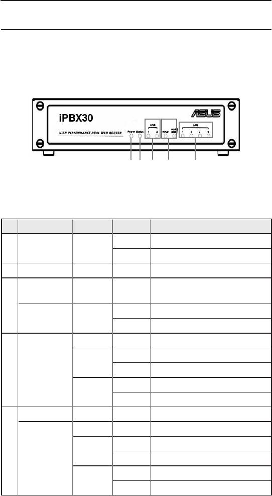
2.4.1 Front Panel
The front panel contains LED indicators that show the status of the unit.
1 2
3
4
5
Figure 2.1 Front Panel Label and LEDs
Table 2.2 Front Panel Label and LEDs
LED Color Status
Indication
ON iPBX30 is powered on.
1 Power Green
OFF iPBX30 is powered off.
2 Status Green
Ide n t i f i es t h e U S B p o rt
USB
LEDs.
3
OFF USB device is not detected.
1-2 Green
ON USB device is detected.
OFF No link is detected.
ON 100Mbps link is detected.
Green
WAN1 and
4
Blinking 100Mbps activity is detected.
WAN2/DMZ
ON 10Mbps link is detected.
Amber
Blinking 10Mbps activity is detected.
LAN Identies the LAN port LEDs.
OFF No link is detected.
ON 100Mbps link is detected.
5
Green
1-4
Blinking 100Mbps activity is detected.
ON 10Mbps link is detected.
Amber
Blinking 10Mbps activity is detected.
8
iPBX30 User Manual
Chapter 2
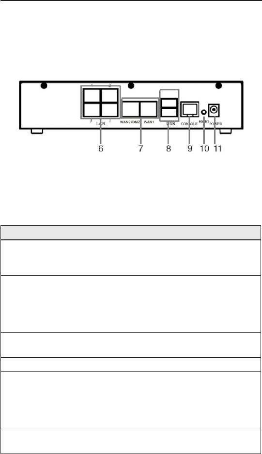
2.4.2 Rear Panel
The rear panel contains the ports for the unit’s data and power
connections.
Figure 2.2 Rear Panel Labels and Connectors
Table 2.3 Rear Panel Labels and LEDs
Connector Indication
LAN Ports: connect to your PC's Ethernet
6 1--4
port, or to the uplink port on your LAN's hub/
switch, using the Ethernet cable.
Dual WAN ports or 1 WAN + 1 DMZ:
connects to your WAN devices, such as
WAN1 and
7
ADSL or cable modem or DMZ network. The
WAN2/DMZ
DMZ network must be connected to the port
labeled as WAN2/DMZ.
USB Ports: connect to USB 1.1 OR 2.0
8 USB
devices
9 Console Not supported.
Reset Button:
1. Reboot the device
10 RESET
2. Reset the system conguration to factory
defaults if pressed for more than 5 seconds.
Power Input Jack: Connect to the supplied
11 POWER
AC adapter.
9
Chapter 2
iPBX30 User Manual
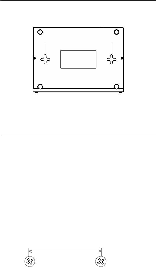
2.4.3 Bottom View
12 12
12.Wall Mount Slots: Use these slots to mount iPBX30 on a wall.
You can mount the iPBX30 in four orientations: front panel up,
rear panel up, left side up or right side up.
2.5 Placement Options
Choose one of the supported placement options for the iPBX30 –
desktop placement and wall mount.
2.5.1 Desktop Placement
You may place the iPBX30 on any at surface. The space-saving
design of iPBX30 occupies only a small area on your desk.
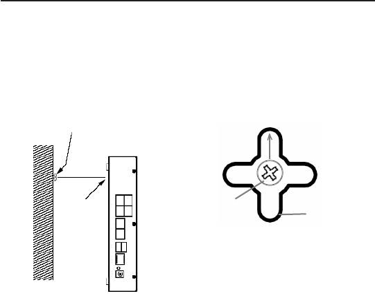
2.5.2 Wall Mount Instructions:
1. Attach two screws on the wall, and with a 150mm distance
between the two screws.
150mm
10
iPBX30 User Manual
Chapter 2
2. Align the screws with the wall mount slots as shown below. The
wall mount design supports four orientations: rear side up, rear
side down, rear side to the left and rear side to the right.
Screw
Wall
Wall
Screw
mount
mount
slot
slot
Maneuver the router so that
b o t h s c r e w s a re i n s e r t e d
into the wall mount slots and
then slowly push the router
Line up the wall mount slot with
downward as shown in the
both screws.
gure above.
11
Оглавление
- List of Figures
- List of Tables
- Chapter 1 Introduction
- Chapter 2 Getting to Know your iPBX30
- 3 Quick Start Guide
- 4 Using the Web UI Management
- 5 Router Setup
- 6 DHCPServerConguration
- 7 Routing
- 8 ConguringDDNS
- 9 ConguringFirewallandNAT
- 10 USB Application
- 11 System Management
- 12 SIP IP-PBX
- 13 IP Addresses, Network Masks, and Subnets
- 14 Troubleshooting
- 15 Index
