Asus ITX-220: 9 ConguringFirewallandNAT
9 ConguringFirewallandNAT: Asus ITX-220

iPBX30 User Manual
Chapter 9
9 ConguringFirewallandNAT
The iPBX30 provides built-in firewall/NAT functions, enabling you
to protect the system against denial of service (DoS) attacks and
other types of malicious accesses to your LAN while providing
Internet access sharing at the same time. You can also specify how
to monitor attempted attacks, and who should be automatically
notied.
This chapter describes how to create/modify/delete ACL (Access
Control List) rules to control the data passing through your network.
You will use rewall conguration pages to:
• Congure rewall global and DoS settings
• Create, modify, delete and view ACL rules.
When you define an ACL rule, you instruct the
iPBX30 to examine each data packet it receives to
determine whether it meets criteria set forth in the
rule. The criteria can include the network or internet
protocol it is carrying, the direction in which it is
traveling (for example, from the LAN to the Internet or
vice versa), the IP address of the sending computer,
the destination IP address, and other characteristics
of the packet data.
If the packet matches the criteria established in a
rule, the packet can either be accepted (forwarded
towards its destination), or denied (discarded),
depending on the action specied in the rule.
9.1 Firewall Overview
9.1.1 Stateful Packet Inspection
The stateful packet inspection engine in the iPBX30 maintains a
state table that is used to keep track of connection states of all the
packets passing through the rewall. The rewall will open a “hole”
to allow the packet to pass through if the state of the packet that
belongs to an already established connection matches the state
maintained by the stateful packet inspection engine. Otherwise,
the packet will be dropped. This “hole” will be closed when the
connection session terminates. No configuration is required for
61

Chapter 9
iPBX30 User Manual
stateful packet inspection; it is enabled by default when the rewall
is enabled. Please refer to section 9.3.1 “Firewall ” to enable or
disable rewall service on the iPBX30.
9.1.2 DoS (Denial of Service) Protection
Both DoS protection and stateful packet inspection provide rst line
of defense for your network. No conguration is required for both
protections on your network as long as rewall is enabled for the
iPBX30. By default, the firewall is enabled at the factory. Please
refer to section 9.3.1 “Firewall ” to enable or disable rewall service
on the iPBX30.
9.1.3 Firewall and Access Control List (ACL)
9.1.3.1 Priority Order of ACL Rule
All ACL rules have a rule ID assigned – the smaller the rule ID, the
higher the priority. Firewall monitors the trafc by extracting header
information from the packet and then either drops or forwards the
packet by looking for a match in the ACL rule table based on the
header information.
The ACL rule checking starts from the rule with the smallest rule ID
until a match is found or all the ACL rules are examined. If no match
is found, the packet is dropped; otherwise, the packet is either
dropped or forwarded based on the action dened in the matched
ACL rule.
9.1.3.2 Tracking Connection State
The stateful packet inspection engine in the firewall keeps track
of the state, or progress, of a network connection. By storing
information about each connection in a state table, iPBX30 is able
to quickly determine if a packet passing through the rewall belongs
to an already established connection. If it does, it is passed through
the rewall without going through ACL rule evaluation.
For example, an ACL rule allows outbound ICMP packet from
192.168.1.1 to 192.168.2.1. When 192.168.1.1 send an ICMP echo
62

iPBX30 User Manual
Chapter 9
request (i.e. a ping packet) to 192.168.2.1, 192.168.2.1 will send an
ICMP echo reply to 192.168.1.1. In the iPBX30, you don’t need to
create another inbound ACL rule because stateful packet inspection
engine will remember the connection state and allows the ICMP
echo reply to pass through the rewall.
9.1.4 Default ACL Rules
The iPBX30 supports two types of access rules:
• ACL Rules: for controlling all access to the computers on the
LAN and DMZ and for controlling access to external networks
for hosts on the LAN and DMZ.
• Self-Access Rules: for controlling access to the IPBX30 itself.
Default Access Rules
• All trafc from external hosts to the hosts on the LAN and DMZ is
denied.
• All traffic originated from the LAN is forwarded to the external
network using NAT.
WARNING: It is not necessary to remove the default
ACL rule from the ACL rule table! It is better to create
higher priority ACL rules to override the default rule.
9.2 NAT Overview
Network Address Translation allows use of a single device, such
as the iPBX30, to act as an agent between the Internet (public
network) and a local (private) network. This means that a NAT
IP address can represent an entire group of computers to any
entity outside a network. Network Address Translation (NAT) is
a mechanism for conserving registered IP addresses in large
networks and simplifying IP addressing management tasks.
Because of the translation of IP addresses, NAT also conceals
true network address from privy eyes and provide a certain degree
security to the local network.
The NAT modes supported are static NAT, dynamic NAT, NAPT,
reverse static NAT and reverse NAPT.
63

Chapter 9
iPBX30 User Manual
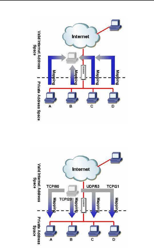
9.2.1 NAPT (Network Address and Port Translation)
or PAT (Port Address Translation)
Also called IP Masquerading, this feature maps many internal
hosts to one globally valid Internet address. The mapping contains
a pool of network ports to be used for translation. Every packet
is translated with the globally valid Internet address and the port
number is translated with an un-used port from the pool of network
ports. The gure below shows that all the hosts on the local network
gain access to the Internet by mapping to only one globally valid
IP address and different port numbers from a free pool of network
ports.
64
iPBX30 User Manual
Chapter 9
Figure 9.1 NAPT – Map Any Internal PCs to a Single Global IP Address
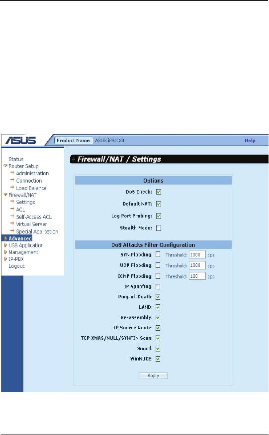
Figure 9.2 Reverse NAPT – Relayed Incoming Packets to the
Internal Host Base on the Protocol, Port Number or IP Address
65

Chapter 9
iPBX30 User Manual
9.2.2 Reverse NAPT / Virtual Server
Reverse NAPT is also called inbound mapping, port mapping, or
virtual server. Any packet coming to the iPBX30 can be relayed
to the internal host based on the protocol, port number and/or IP
address specified in the ACL rule. This is useful when multiple
services are hosted on different internal hosts. Web server (TCP/80)
is hosted on PC A, telnet server (TCP/23) on PC B, DNS server
(UDP/53) on PC C and FTP server (TCP/21) on PC D. This means
that the inbound traffic of these four services will be directed to
respective host hosting these services.
9.3 Firewall Settings – (Firewall/NAT ->Settings)
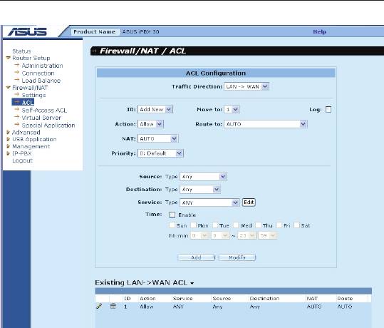
9.3.1 Firewall Options
The table below lists the rewall options parameters.
Table 9.1. Firewall Options Parameters
Field Description
DoS Check Check or uncheck this box to enable or disable DoS
check. When DoS check is disabled, the following
functionalities are disabled:
• Stateful packet inspection
• Skip all DoS attack check
Default NAT
Log Port Probing Connection attempt to closed ports will be logged if
this option is enabled.
Stealth Mode If enabled, iPBX30 will not respond to remote peer’s
attempt to connect to the closed TCP/UDP ports.
To congure rewall settings, follow the instructions below:
1. Click on
Firewall/NAT ->Settings
menu to open the
Firewall
Settings
conguration page.
2. Check or uncheck individual check box for each rewall option.
3. Click
Apply
to save the settings.
66

iPBX30 User Manual
Chapter 9
9.3.2 DoSConguration
The iPBX30 has an Attack Defense Engine that protects internal
networks from Denial of Service (DoS) attacks such as SYN
flooding, IP smurfing, LAND, Ping of Death and all re-assembly
attacks. It can drop ICMP redirects and IP loose/strict source routing
packets. For example, a security device with the iPBX30 Firewall
provides protection from “WinNuke”, a widely used program to
remotely crash unprotected Windows systems in the Internet. The
iPBX30 Firewall also provides protection from a variety of common
Internet attacks such as IP Spoofing, Ping of Death, Land Attack,
and Reassembly attacks.
9.3.2.1 DoSProtectionCongurationParameters
The table below provides explanation for each type of DoS attacks.
You may check or uncheck the check box to enable or disable the
protection for each type DoS attacks.
Table 9.2. DoS Attack Denition
Field Description
I P S o u r c e
Intruder uses “source routing” in order to break into the
Route
target system.
IP Spoong Spoong is the creation of TCP/IP packets using somebody
else’s IP address. IP spoofing is an integral part of many
network attacks that do not need to see responses.
Land Attacker sends out packets to the system with the same
source and destination IP address being that of the target
system and causes the target system trying to resolve an
infinite series of connections to itself. This can cause the
target system to slow down drastically.
Ping of Death An attacker sends out larger than 64KB packets to cause
certain operating system to crash.
Smurf An attacker issues ICMP echo requests to some broadcast
addresses. Each datagram has a spoofed IP source address
to be that of a real target-host. Most of the addressed hosts
will respond with an ICMP echo reply, but not to the real
initiating host, instead all replies carry the IP address of the
previously spoofed host as their current destination and
cause the victim host or network to slow down drastically.
67

Chapter 9
iPBX30 User Manual
Field Description
S Y N / I C M P /
Check or un-check this option to enable or disable the
UDP Flooding
logging for SYN/ICMP/UDP ooding attacks. These attacks
involve sending lots of TCP SYN/ICMP/UDP to a host in a
very short period. iPBX30 will not drop the ooding packets
to avoid affecting the normal trafc.
T C P X M A S /
A hacker may be scanning your system by sending these
NULL/ FIN Scan
specially formatted packets to see what services are
available. Sometimes this is done in preparation for a
future attack, or sometimes it is done to see if your system
might have a service, which is susceptible to attack.
XMAS scan:
A TCP packet has been seen with a
sequence number of zero and the FIN, URG, and PUSH
bits are all set.
NULL scan:
A TCP packet has been seen with a
sequence number of zero and all control bits are set to
zero.
FIN scan:
A hacker is scanning the target system using
a “stealth” method. The goal of the hacker is to nd out if
they can connect to the system without really connecting
using the “FIN” scanning. It attempts to close a non-
existent connection on the server. Either way, it is an error,
but systems sometimes respond with different error results
depending upon whether the desired service is available or
not.
Re-assembly In the teardrop attack, the attacker’s IP puts a confusing
offset value in the second or later fragment. If the receiving
operating system does not have a plan for this situation, it
can cause the system to crash.
WinNUKE Check or un-check this option to enable or disable
protection against Winnuke attacks. Some older versions
of the Microsoft Windows OS are vulnerable to this attack.
If the computers in the LAN are not updated with recent
versions/patches, you are advised to enable this protection
by checking this check box.
68
iPBX30 User Manual
Chapter 9
9.3.2.2 ConguringDoSSettings
To congure DoS settings, follow the instructions below:
1. Click on
Firewall / NAT ->Settings
menu to open the Firewall
General conguration page.
2. Check or uncheck individual check box for each type DoS
protection.
3. Click
Apply
to save the settings.
Figure 9.3. Firewall General Conguration Page
9.4 ACLRuleCongurationParameters
9.4.1 ACLRuleCongurationParameters
The table below describes the configuration parameters firewall
inbound, outbound and self-access ACL rules.
69

Chapter 9
iPBX30 User Manual
Table 9.3. ACL Rule Conguration Parameters
Field Description
Trafc Direction
– select from the available option in the drop-
down list to congure the ACL.
For dual-WAN conguration, two options are available – LAN ->WAN and
WAN ->LAN.
For WAN + DMZ configuration, six options are available – LAN ->WAN,
WAN ->LAN, LAN ->DMZ, DMZ->LAN, WAN ->DMZ and DMZ ->WAN.
ID
Add New
Click on this option to add a new ACL rule.
Rule Number
Select a rule from the drop-down list, to modify its
settings.
Move to
This option allows you to set a priority for this rule. The iPBX30 Firewall acts
on packets based on the priority of the rules. Set a priority by specifying a
number for its position in the list of rules:
1 (First)
This number marks the highest priority.
Other
Select other numbers to indicate the priority you wish to
numbers
assign to the rule.
Log
Check this box to enable loggingfor this ACL rule; otherwise, keep it
unchecked.
Action
Allow
Select this button to congure the rule as an allow rule.
This rule when bound to the Firewall will allow matching
packets to pass through.
Deny
Select this button to congure the rule as a deny rule.
This rule when bound to the Firewall will not allow
matching packets to pass through.
Route to
– keep the setting to “AUTO” unless packets are routed to specic interface.
Available options include AUTO, eth1 (WAN1), eth2 (WAN2), PPP1 (WAN1-
unnumbered), PPP1 (WAN2-unnumbered), PPP3 (WAN1-PPPoE1), PPP4
(WAN1-PPPoE2), PPP5 (WAN2-PPPoE1), PPP6 (WAN2-PPPoE2). If WAN
interface is set to DMZ mode, only AUTO, eth1, PPP1/3/4 are available.
These options are selectable from the drop-down list. If AUTO is selected,
the router will route the packets based on the information in the routing
table.
70

iPBX30 User Manual
Chapter 9
Field Description
NAT
None
Select this option if you don’t intend to use NAT in this
ACL rule.
IP Address
Select this option to specify the source IP address for
outgoing trafc. This option is called.
Auto
iPBX30 automatically uses the IP address of the
interface as the source IP address for outgoing trafc. It
is recommended that you select this option if NAT is to
be used for outgoing trafc.
Source
This option allows you to set the source network to which this rule
should apply. Use the drop-down list to select an option:
Any
This option allows you to apply this rule to all the
computers in the source network, such as those on the
Internet for the inbound trafc or all the computers in the
local network for outbound trafc.
IP Address
This option allows you to specify an IP address on which
this rule will be applied.
IP Address
Specify the appropriate network address
Subnet
This option allows you to include all the computers that
are connected in an IP subnet. When this option is
selected, the following elds become available:
Field Description
Address
Enter the appropriate IP address.
Mask
Enter the corresponding subnet mask.
MAC Address
This option allows you to specify a MAC address on
which this rule will be applied.
MAC
Enter the desired MAC address.
Destination
This option allows you to set the destination network to which
this rule should apply. Use the drop-down list to select one of the
following options:
Any
This option allows you to apply this rule to all the
computers in the local network for inbound trafc or any
computer in the Internet for outbound trafc.
71

Chapter 9
iPBX30 User Manual
IP Address,
Select any of these options and enter details as
Subnet
described in the Source IP section above.
Service
Select a service, from the drop-down list, to which this rule
should apply. If the desired service is not listed, click on the
Edit button to create a new service.
Time
Select a time slot during which this rule should apply.
Enable
Check this box if you want to activate the ACL rule at the
time specied. Uncheck this box to make the rule active
at all times
Date and Time
Chck the desired dates and time for this ACL rule.
Table 9.4. Service Conguration Parameters
Field Description
Service Name
Enter a distinctive name identifying the new service.
Protocol
Select a protocol type from the drop-down list. Available options are All,
TCP, UDP, ICMP, IGMP, AH ESP and TCP/UDP.
Port
This option allows you to specify the port number(s) used by the device.
Use the drop-down list to select one of the following options:
Any
Select this option if the service is used to designate an
arbitary application.
Single
Select this option if the service uses a specific port
number.
Port Number
Enter the port number
Range
Select this option if the service uses a range of ports.
The following elds become available for entry when this
option is selected.
Start Port
Enter the starting value of the port range
End Port
Enter the ending value of the port range
72

iPBX30 User Manual
Chapter 9
Field Description
This option allows you to select the ICMP message type for the service. The
supported ICMP message types are:
• Any (default)
• 0: Echo reply
• 1: Type 1
• 2: Type 2
• 3: Dst unreach: destination unreachable
• 4: Src quench: source quench
• 5: Redirect
• 6: Type 6
• 7: Type 7
• 8: Echo req:
• 9: Router advertisement
• 10: Router solicitation
• 11: Time exceed: time exceeded
• 12: Parameter problem
• 13: Timestamp request
• 14: Timestamp reply
• 15: Info request: information request
• 16: Info reply: information reply
• 17: Addr mask req: address mask request
• 18: Addr mask reply: address mask reply
9.5 ConguringACLRules–(Firewall->ACL)
By creating ACL rules in the ACL configuration page, you can
perform access control (allow or deny) to both the trusted and un-
trusted networks.
Options in this conguration page allow you to:
• Add a rule, and set parameters for it
• Modify an existing rule
• Delete an existing rule
• View congured ACL rules
73
Chapter 9
iPBX30 User Manual
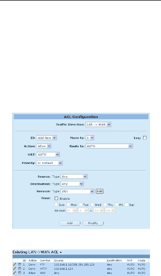
Figure 9.4. ACL Conguration Page
9.5.1 Add an ACL Rule
To add an ACL rule, follow the instructions below:
1. Click
Firewall/NAT ->ACL
menu to open the ACL Rule
conguration page.
2. Select an option from the
Traffic Direction
drop-down list. For
example, if you want to create an ACL to lter trafc originated from
LAN and destined to WAN, then choose
LAN ->WAN
option.
3. Select
Add New
from the “ID” drop-down list.
4. Set desired action (Allow or Deny) from the
Action
drop-down list.
5. Select from the
Route To
drop-down list if you intend to direct
the trafc to a specic interface. Choose AUTO if you want to
have the iPBX30 to route the trafc automatically.
6. Choose NAT type and enter the required information for the
selected NAT type.
74
iPBX30 User Manual
Chapter 9
7. Make changes to any or all of the following fields: source/
destination IP, service, time and log.
8. Assign a priority for this rule by selecting a number from the
Move to
drop-down list. Note that the number indicates the
priority of the rule with 1 being the highest. Higher priority rules
will be examined prior to the lower priority rules by the rewall.
9. Click on the
Add
button to create the new ACL rule. The new
ACL rule will then be displayed in the inbound access control list
table at the bottom half of the Inbound ACL Conguration page.
The gure below illustrates how to create a rule to deny outbound
HTTP trafc originated from the host w/ IP address 192.168.1.129.
Figure 9.5. ACL Conguration Example
Figure 9.6. Sample ACL List Table
75

Chapter 9
iPBX30 User Manual
9.5.2 Modify an ACL Rule
To modify an ACL rule, follow the instructions below:
1.Click
Firewall/NAT ->ACL
menu to open the ACL Rule
Conguration page.
2. Click on the icon of the rule to be modied in the inbound
ACL table or select the rule number from the
ID
drop-down list.
3. Make desired changes to any or all of the following elds: action,
source/destination IP, service, time and log.
4. Click on the
Modify
button to modify this ACL rule. The new
settings for this ACL rule will then be displayed in the access
control list table at the bottom half of the ACL Configuration
page.
9.5.3 Delete an ACL Rule
To delete an ACL rule, click on the icon in front of the rule to be
deleted.
9.5.4 Display ACL Rules
To see existing ACL rules, just open the ACL Rule Configuration
page by clicking
Firewall/NAT ->ACL
menu and then select a trafc
direction from the T
rafc Direction
drop-down list.
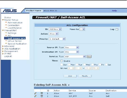
9.6 ConguringSelf-AccessACLRules
–(Firewall/NAT ->Self-Access ACL)
Self-Access rules control access to/from the iPBX30 itself. You may
use Self-Access Rule Conguration page to:
• Add a Self-Access rule
• Modify an existing Self-Access rule
• Delete an existing Self-Access rule
• View existing Self-Access rules
76
iPBX30 User Manual
Chapter 9
Figure 9.7. Self-Access ACL Conguration Page
9.6.1 Add a Self-Access Rule
To add a Self-Access rule, follow the instructions below:
1. Click
Firewall/NAT ->Self-Access ACL
menu to open the Self-
Access Rule Conguration page.
2. Select “
Add New
” from the “ID” drop-down list.
3. Set desired action (Allow or Deny) from the “
Action
” drop-down list.
4. Assign a priority for this rule by selecting a number from the
“
Move to
” drop-down list. Note that the number indicates the
priority of the rule with 1 being the highest. Higher priority rules
will be examined prior to the lower priority rules by the rewall.
5. Make desired changes to any or all of the following fields:
source/destination IP, service, time and log.
6. Click on the "
Add
" button to create the new Self-Access
rule. The new rule will then be displayed in the Existing Self-
Access ACL list table at the bottom half of the Self-Access ACL
conguration page.
77
Chapter 9
iPBX30 User Manual
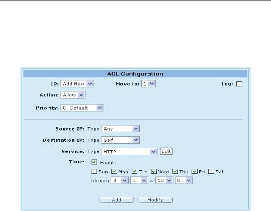
Example
The gure below shows a sample self-access ACL conguration to
allow HTTP trafc from any one to iPBX30.
Figure 9.8. Self-Access ACL Conguration Example
9.6.2 Modify a Self-Access Rule
To modify a Self-Access rule, follow the instructions below:
1. Click
Firewall/NAT ->Self-Access ACL
menu to open the Self-
Access ACL conguration page.
2. Click on the icon of the Self-Access rule to be modied in the
Existing Self-Access ACL
table or select the Self-Access ACL
from the
ID
drop-down list.
3. Make desired changes to any or all of the following elds: action,
source/destination IP, service, time and log.
4. Click on the "
Modify
" button to save the changes. The new
settings for this Self-Access rule will then be displayed in the
Existing Self-Access ACL table located at the bottom half of the
Self-Access ACL conguration page.
9.6.3 Delete a Self-Access Rule
To delete a Self-Access rule, click on the icon of the rule to be
deleted.
78
iPBX30 User Manual
Chapter 9
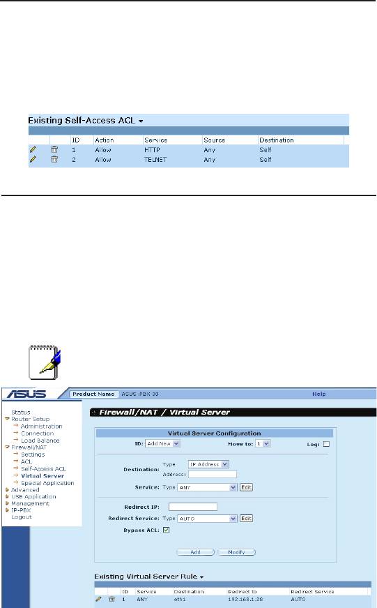
9.6.4 ViewConguredSelf-AccessRules
To see existing Self-Access Rules, just open the Self-Access ACL
configuration page by clicking
Firewall/NAT ->Self-Access ACL
menu.
9.7 CongureVirtualServer
Virtual server allows you to congure up to ten public servers (such
as a Web, E-mail, FTP server and etc.) accessible by external
users of the Internet. Each service is provided by a dedicated
server configured with a fixed IP Address. Although the internal
service addresses are not directly accessible to the external users
the router is able to identify the service requested by the service
port number and redirects the request to the appropriate internal
server.
Note: iPBX30 supports only one server of any
particular type at a time.
Figure 9.9. Virtual Server Conguration Page
9.7.1 VirtualServerCongurationParameters
The table below describes the conguration parameters available
for virtual server conguration.
79

Chapter 9
iPBX30 User Manual
Table 9.5. Virtual Server Conguration Parameters
Setting Description
ID
Add New
Click on this option to add a new virtual server.
Number
Select the ID of a virtual server from the drop-down list to
modify its settings.
Move to
This option allows you to set a priority for virtual server rule check. NAT
does the IP and/or port mapping based on the priority of the rules. Set a
priority by specifying a number for its position in the list of rules
1 (First)
This number marks the highest priority.
Other
Select other numbers to indicate the priority you wish to
numbers
assign to the rule.
Destination
This option allows you to set the destination network to which this rule
should apply. Use the drop-down list to select one of the following options:
IP Address
Enter the IP address of the virtual server if the virtual
server has a known public IP address.
Interface
Use the IP address of the selected interface as the
destination IP address. Available options are:
eth1 (WAN1)
eth2 (WAN2)
ppp1 (WAN1 – unnumbered)
ppp2 (WAN2 – unnumbered)
ppp3 (WAN1 – PPPoE 1)
ppp4 (WAN1 – PPPoE 2)
ppp5 (WAN2 – PPPoE 1)
ppp6 (WAN2 – PPPoE 2)
Service
Select a service, from the drop-down list, to which this rule
should apply. If the desired service is not listed, click on
the
Edit
button to create a new service.
Redirect IP
Enter the IP address of the computer (usually a server in
your LAN) that you want the incoming trafc to be directed.
For example, if IP address of the web server on your LAN
is 192.168.1.28, please enter 192.168.1.28 here.
80

iPBX30 User Manual
Chapter 9
Setting Description
Redirect
Select a service, from the drop-down list, to which this rule
Service
should apply. If the desired service is not listed, click on
the "
Edit
" button to create a new service.
Bypass ACL
Check this option if you do not want firewall to perform
access control on this virtual server. This means that
the virtual server allows anyone to access the service
provided. If you want to control who has access to this
virtual server, un-check this option and create a proper
ACL rule to control access to the virtual server.
Table 9.6. Port Numbers for Popular Applications
Application Service Port Numbers
AOE II (Server) 2300-2400
AUTH 113
Baldurs Gate II 2300-2400
Battle Isle 3004-3004
Counter Strike 27005-27015
Cu See Me 7648-7648, 56800, 24032
Diablo II 4000-4000
DNS UDP 53-53
FTP TCP 21-21
FTP TCP 20(ALG)-21
GOPHER TCP 70-70
HTTP TCP 80-80
THHP8080 TCP 8080-80880
HTTPS TCP 443-443
I-phone 5.0 TCP/UDP 22555-22555
ISAKMP UDP 500-500
mirc 66011-700
MSN Messenger 1863 ALG
Need for Speed 5 9400-9400
Netmeeting Audio TCPP 1731-1731
Netmeeting Call TCP 1720-1720
Netmeeting Conference UDP 495000-49700
Netmeeting File Transfer TCP 1503--1503
81
Chapter 9
iPBX30 User Manual
Application Service Port Numbers
Netmeeting or VoIP 1503-1503, 1720(ALG)
NEWS TCP 119-119
PC Anywhere TCP 5631
PC Anywhere TCP 5631, UDP 5632
POP3 TCP 110-110
Powwow Chat 13233-13233
Red Alert II 1234-1237
SMTP TCP 25-25
Sudden Strike 2300-2400
TELNET TCP 23-23
Win VNC UDP 5800-5800
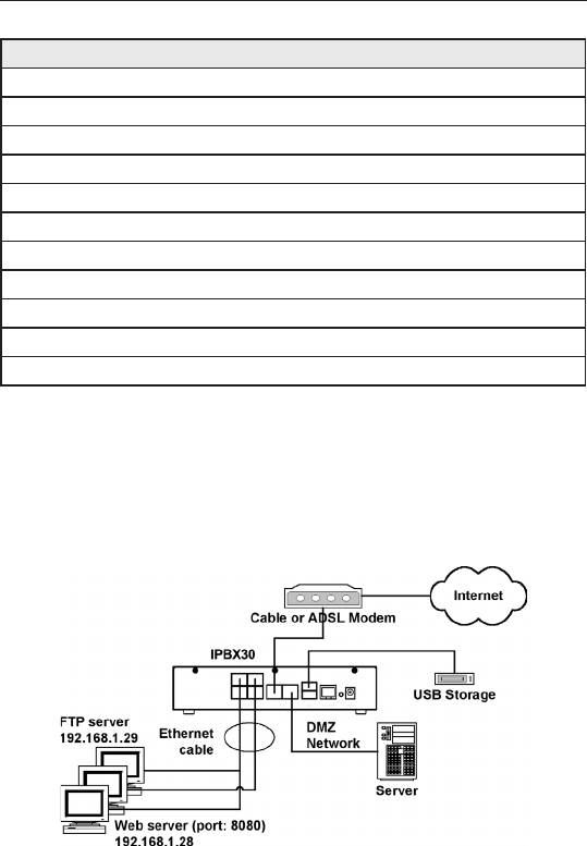
9.7.2 Virtual Server Example 1 – Web Server
The gure below shows illustrates the network topology for the web
server deployment. This web server provides HTTP service using
TCP port 8080.
Figure 9.10. Virtual Server Deployment Topology
Following describes the procedure to setup the web server.
1. Click the
Firewall/NAT ->Virtual Server
menu to open the
Virtual Server conguration page.
2. Select destination IP type and service type.
82
iPBX30 User Manual
Chapter 9
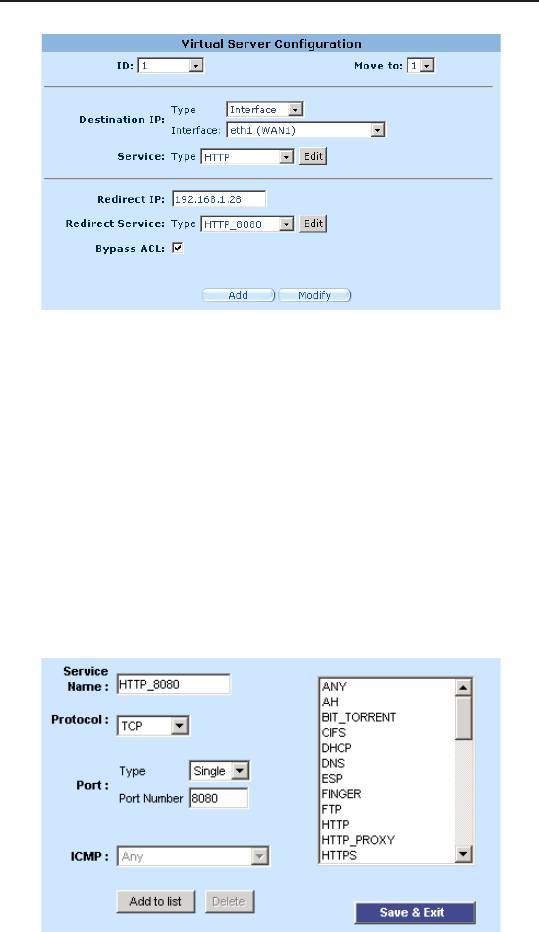
Figure 9.11. Virtual Server Example 1 – Web Server
3. Enter the IP address of the web server, which is 192.168.1.28,
in
Redirect IP
eld.
4. Since the web server is not using the standard TCP port, which
is 80, for providing the http service, a new service type must
be created for http service using TCP port 80. Click on the
Edit
button on the redirect service eld to create a new service type.
In the popped up Service conguration page, enter the service
name, protocol and port number and then click on the
Add to
list
to create the new service type, HTTP_8080. Finally, click
the
Save & Exit
button to save the new service.
Figure 9.12. Adding a New Service
83
Chapter 9
iPBX30 User Manual
5. Select the service, HTTP_8080, from the Redirect Service drop-
down list.
6. Click
Add
to save the virtual server settings.
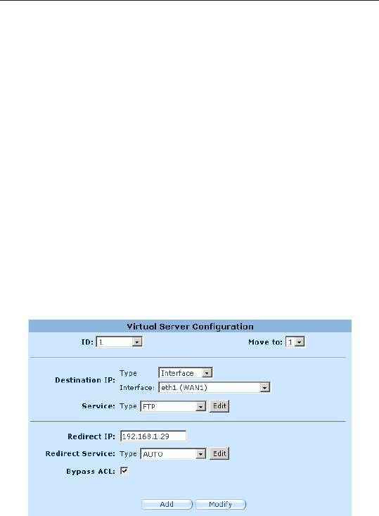
9.7.3 Virtual Server Example 2 – FTP Server
This FTP server provides FTP service using standard FTP port.
Following describes the procedure to setup the FTP server.
1. Click the
Firewall/NAT ->Virtual Server
menu to open the
Virtual Server conguration page.
2. Enter the needed information.
3. Click
Add
to save the virtual server settings.
Figure 9.13. Virtual Server Example 2 – FTP Server
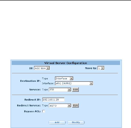
9.7.4 Virtual Server Example 3 – FTP Server with
Access Control
This example is similar to the previous example described in
section 9.7.3 but with access control dictated by the firewall ACL
rule. In this example, we want to limit the FTP server access to a
network, 168.192.128.0.
The following describes the procedure to setup such a FTP service.
84
iPBX30 User Manual
Chapter 9
1. Create an FTP virtual server.
a) Click the
Firewall/NAT ->Virtual Server
menu to open the
Virtual Server Conguration.
b) Enter the needed information.
c) Make sure that
Bypass ACL
box is unchecked.
d) Click
Add
to save the virtual server settings.
Figure 9.14. Virtual Server Example 3 – FTP Server
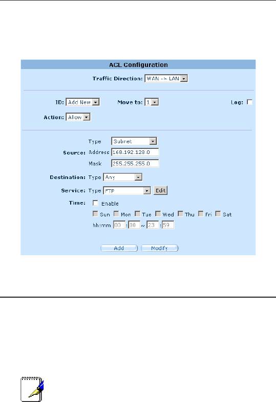
2. Create an ACL rule to control access to the FTP server.
a) Click
Firewall ->ACL
menu to open the ACL Rule conguration
page.
b) Select
WAN ->LAN
option from the
Trafc Direction
drop-down
list.
c) Select
Add New
from the
ID
drop-down list.
d) Select
Allow
from the
Action
drop-down list.
e) Select
Subnet
from the
Source Type
drop-down list.
f) Enter the
168.192.128.0
and
255.255.255.0
for the
Source
Address
and
Mask
elds respectively.
g) Select
FTP
from the
Service Type
drop-down list.
h) Assign a priority for this rule by selecting a number from the
Move to
drop-down list. Note that the number indicates the
priority of the rule with 1 being the highest. Higher priority rules
85
Chapter 9
iPBX30 User Manual
will be examined prior to the lower priority rules by the rewall.
i) Click on the
Add
button to create the new ACL rule.
Figure 9.15. Firewall ACL for Virtual Server Example 3 – FTP Server
9.8 ConguringSpecialApplication
Some applications use multiple TCP/UDP ports to transmit data.
Due to NAT, these applications cannot work with the router. Special
Application setting allows some of these applications to work
properly.
Note: Only one PC can use one particular special
application at a time.
9.8.1 SpecialApplicationCongurationParameters
The table below describes the conguration parameters available
for virtual server conguration.
86

iPBX30 User Manual
Chapter 9
Table 9.7. Special Application Conguration Parameters
Setting Description
Enabled Check this box to activate the policy.
Trigger Protocol Select the protocol type from the drop-down list. The
available options are TCP, UDP and TCP/UDP.
Outgoing (Trigger)
The port range this application uses when it sends
Port
outbound packets. The outgoing port numbers act
as the trigger. When the router detects the outgoing
packets with these port numbers, it will allow the
corresponding inbound packets with the incoming port
numbers specied in the
Incoming Port Range
eld to
pass through the router.
Incoming Protocol The protocol that the corresponding inbound packet
used. The available options are TCP, UDP and TCP/
UDP.
Incoming Port The port range that the corresponding inbound packet
used. The port range is indicated by a pair of numbers w/
a dash separating the numbers, e.g. 100-200. Multiple
port ranges is separated by a comma, e.g. 100-200,
700-800.
Comment You may enter a description for the application here, e.g.
a name identifying the application.
Table 9.8. Port Numbers for Popular Applications
Application Outgoing Port
Incoming Port Range
Number
Battle.net 6112 6112
DialPad 7175 51200, 51201, 51210
ICU II 2019 2000-2038, 2050-2051,
2069, 2085, 3010-3030
MSN Gaming Zone 47624 2300-2400, 28800-29000
PC to Phone 12053 12120, 12122, 150-24220
Quick Time 4 554 6970-6999
wowcall 8000 4000-4020
Yahoo Messenger 5050 5000-5101
87
Chapter 9
iPBX30 User Manual
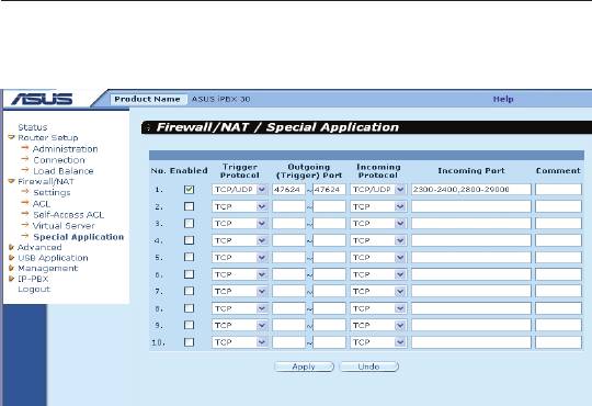
9.8.2 Special Application Example
Figure 9.16. Special Application Conguration Page
Following describes the procedure to setup a special application for
MSN Gaming Zone.
1. Click the
Firewall/NAT ->Special Application
menu to open the
Special Application conguration page.
2. Check
Enabled
checkbox.
3. Select
TCP/UDP
from the trigger protocol drop-down list. If you
are not sure whether the application uses TCP or UDP protocol,
you may select TCP/UDP in this eld.
4. Enter outgoing port range, in this case: 47624 ~ 47624.
5. Select
TCP/UDP
from the incoming protocol drop-down list.
If you are not sure whether the application uses TCP or UDP
protocol, you may select TCP/UDP in this eld.
6. Enter incoming port range, in this case: 2300-2400 and
28800-29000
7. In the
Comment
eld, enter the name identifying this application,
which is MSN Gaming Zone in this instance.
8. Click
Apply
to save the settings.
88
Оглавление
- List of Figures
- List of Tables
- Chapter 1 Introduction
- Chapter 2 Getting to Know your iPBX30
- 3 Quick Start Guide
- 4 Using the Web UI Management
- 5 Router Setup
- 6 DHCPServerConguration
- 7 Routing
- 8 ConguringDDNS
- 9 ConguringFirewallandNAT
- 10 USB Application
- 11 System Management
- 12 SIP IP-PBX
- 13 IP Addresses, Network Masks, and Subnets
- 14 Troubleshooting
- 15 Index
