Pioneer VSX-921: Connecting a satellite/cable receiver or other set-top box Connecting other audio components
Connecting a satellite/cable receiver or other set-top box Connecting other audio components: Pioneer VSX-921
Table of contents
- IMPORTANT
- Contents
- Before you start
- Remote control
- Connecting your equipment
- Placing the speakers Connecting the speakers
- Bi-amping your speakers Installing your speaker system
- Selecting the Speaker system About the audio connection About the video converter
- About HDMI
- Connecting your TV and playback components Connecting your DVD player with no HDMI output
- Connecting an HDD/DVD recorder, BD recorder and other video sources
- Connecting a satellite/cable receiver or other set-top box Connecting other audio components
- MULTI-ZONE setup Sub Zone Input functions available Sub Zone Input functions available Connecting AM/FM antennas
- Connecting to the network through LAN interface Connecting to a wireless LAN Plugging in the receiver
- Basic Setup Canceling the demo display Automatically conducting optimum sound tuning (Full Auto MCACC)
- Operation Mode Setup
- Operable functions/ Descriptions Page
- Basic playback Playing a source Listening in surround sound Playing an iPod
- Listening to the radio Playing a USB device
- Playback with HOME MEDIA GALLERY inputs Bluetooth ADAPTER for Wireless Enjoyment of Music
En
13
02
Connecting your equipment
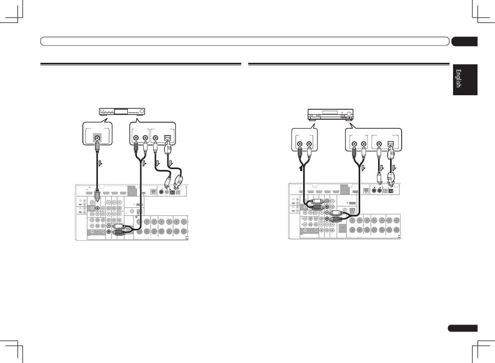
Connecting a satellite/cable receiver or other set-top box
Satellite and cable receivers, and terrestrial digital TV tuners are all examples of so-called ‘set-top
boxes’.
When you set up the receiver you’ll need to tell the receiver which input you connected the set-top
box to (see
The Input Setup menu
on Operating Instructions in CD-ROM).
HDMI
VIDEO
CONTROL
IR
COMPONENT VIDEO
VIDEO IN
TV/SAT
IN
ZONE 2
DVR/BDR CD-R/TAPE ZONE 2
DVR/
BDR
OUT
OUT
DVD IN
IN
IN
IN
IN
CD
L
R
L
R
IN
L
R
OUT
OUT
VIDEO
IN
DVD IN
BD IN
DVR/BDR IN
FM UNBAL
75
FRONT
CENTER
SURROUND
SURROUND BACK / ZONE 2
R
L
R
L
R
L
(Single)
AM LOOP
(
CD
)
(
DVD
)
TV/SAT
VIDEO
DVD
Y
P
B
P
R
(
DVR/BDR
)
(
TV/SAT
)
COAXIAL
(10/100)
LAN
AUDIO
PRE OUT
SPEAKERS
ANTENNA
OPTICAL
ASSIGN
ABLE
ASSIGNABLE
ASSIGNABLE
OUT
MONITOR
OUT
MONITOR
OUT
SUBWOOFER
IN
1
(DVD)
IN
1
(DVR/
BDR)
IN
2
ASSIGNABLE
1
IN
1
IN
2
IN
1
IN
2
SELECT
SELECT
CAUTION:
SPEAKER IMPEDANCE
6 -16 .
ATTENTION:
ENCEINTE D’IMPEDANCE DE
6 -16 .
F
A
OUT
IN
OUT
IN
DC OUTPUT
for WIRELESS LAN
(OUTPUT 5 V
0.1 A MAX)
ADAPTER PORT
(OUTPUT 5 V 0.6 A MAX)
VIDEO OUT
VIDEO
ANALOG
R
AUDIO OUT
DIGITAL OUT
COAXIAL
OPTICAL
L
Select one
STB
!
VSX-1021 only:
If your set-top box is equipped with an HDMI output terminal, we recommend connecting it to the
receiver’s
HDMI
IN 1
terminal. When doing so, also connect the receiver and TV by HDMI (see
Connecting using HDMI
on page 11 ).
Connecting other audio components
This receiver has both digital and analog inputs, allowing you to connect audio components for
playback.
When you set up the receiver you’ll need to tell the receiver which input you connected the compo-
nent to (see also
The Input Setup menu
on Operating Instructions in CD-ROM).
HDMI
VIDEO
CONTROL
IR
COMPONENT VIDEO
VIDEO IN
TV/SAT
IN
ZONE 2
DVR/BDR
CD-R/TAPE
ZONE 2
DVR/
BDR
OUT
OUT
DVD IN
IN
IN
IN
IN
CD
L
R
L
R
IN
L
R
OUT
OUT
VIDEO
IN
DVD IN
BD IN
DVR/BDR IN
FM UNBAL
75
FRONT
CENTER
SURROUND
SURROUND BACK / ZONE 2
R
L
R
L
R
L
(Single)
AM LOOP
(
CD
)
(
DVD
)
TV/SAT VIDEO
DVD
Y
P
B
P
R
(
DVR/BDR
)
(
TV/SAT
)
COAXIAL
(10/100)
LAN
AUDIO
PRE OUT
SPEAKERS
ANTENNA
OPTICAL
ASSIGN
ABLE
ASSIGNABLE
ASSIGNABLE
OUT
MONITOR
OUT
MONITOR
OUT
SUBWOOFER
IN
1
(DVD)
IN
1
(DVR/
BDR)
IN
2
ASSIGNABLE
1
IN
1
IN
2
IN
1
IN
2
SELEC
SELEC
CAUTION:
SPEAKER IMPEDANCE
6 -16 .
ATTENTION:
ENCEINTE D’IMPEDANCE DE
6 -16 .
A
OUT
IN
OUT
IN
DC OUTPUT
for WIRELESS LAN
(OUTPUT 5 V
0.1 A MAX)
ADAPTER PORT
(OUTPUT 5 V 0.6 A MAX)
DIGITAL OUT
COAXIAL
OPTICAL
ANALOG
R
L
AUDIO OUT
ANALOG
R
L
AUDIO IN
CD-R, MD, DAT, etc.
Select one
!
If you’re connecting a recorder, connect the analog audio outputs to the analog audio inputs on the
recorder.
!
If your turntable has line-level outputs (i.e., it has a built-in phono pre-amp), connect it to the
CD
inputs instead.
