Pioneer DEH-X7500SD: Power amp (sold separately)
Power amp (sold separately): Pioneer DEH-X7500SD
a Blue/white
The pin position of the ISO connector will dif-
fer depending on the type of vehicle. Connect
a and b when Pin 5 is an antenna control
type. In another type of vehicle, never con-
nect
a and b.
b Blue/white
Connect to system control terminal of the
power amp (max. 300 mA 12 V DC).
c Blue/white
Connect to auto-antenna relay control termi-
nal (max. 300 mA 12 V DC).
d Speaker leads
White: Front left
+
White/black: Front left
*
Gray: Front right
+
Gray/black: Front right
*
Green: Rear left
+ or subwoofer +
Green/black: Rear left
* or subwoofer *
Violet: Rear right
+ or subwoofer +
Violet/black: Rear right
* or subwoofer *
e ISO connector
In some vehicles, the ISO connector may be
divided into two. In this case, be sure to con-
nect to both connectors.
Notes
! Change the set up menu of this unit (refer to
the operation manual). The subwoofer output
of this unit is monaural.
! When using a subwoofer of 70 W (2 W), be
sure to connect the subwoofer to the violet
and violet/black leads of this unit. Do not
connect anything to the green and green/
black leads.
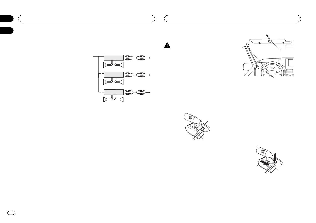
Power amp (sold separately)
Perform these connections when using the op-
tional amplifier.
1
1
3
2
4
3
8
5
5
3
2
6
7
7
9
9
2
1
1 System remote control
Connect to Blue/white cable.
2 Power amp (sold separately)
3 Connect with RCA cable (sold separately)
4 To Rear output
5 Rear speaker
6 To Front output
7 Front speaker
8 To subwoofer output
9 Subwoofer
! Only for DEH-X8500DAB and DEH-X8500BT
CAUTION
It is extremely dangerous to allow the micro-
phone lead to become wound around the steer-
ing column or shift lever. Be sure to install the
unit in such a way that it will not obstruct driv-
ing.
Note
Install the microphone in a position and orienta-
tion that will enable it to pick up the voice of the
person operating the system.
When installing the microphone on the sun visor
1
Fit the microphone lead into the groove.
1
2
1 Microphone lead
2 Groove
2
Install the microphone clip on the sun
visor.
With the sun visor up, install the microphone
clip. (Lowering the sun visor reduces the voice
recognition rate.)
1
2
1 Microphone clip
2 Clamp
Use separately sold clamps to secure the
lead where necessary inside the vehicle.
When installing the microphone on the steering column
1
Detach the microphone base from the mi-
crophone clip.
To detach the microphone base from the micro-
phone clip, slide the microphone base.
1
2
3
1 Microphone
2 Microphone clip
3 Microphone base
Connections
4
Section
Installing the microphone
En
02 03
Table of contents
- DIN front/rear mount
- This unit
- Power amp (sold separately)
- Adjusting the microphoneangle
- Montage avant/arrière DIN
- Cet appareil
- Amplificateur de puissance(vendu séparément)
- Si vous installez lemicrophone sur le pare-soleil
- Montaggio DIN anteriore/posteriore
- Questa unità
- Amplificatore di potenza(venduto a parte)
- Installazione del microfonosull ’aletta parasole
- Montaje delantero/posteriorde DIN
- Esta unidad
- Amplificador de potencia(se vende por separado)
- Instalación del micrófono enel parasol
- Front-/Rückmontage nach DIN
- Dieses Gerät
- Leistungsverstärker (separaterhältlich)
- Befestigen des Mikrofons ander Sonnenblende
- DIN-bevestiging voor/achter
- Dit toestel
- Versterker (apart verkrijgbaar)
- De hoek van de microfoonafstellen
- Переднее/заднеекрепление стандарта DIN
- Данное устройство
- Усилитель мощности(приобретается отдельно)
- При установке микрофона насолнцезащитном козырьке


