Pioneer AVD-W7900: Connection and installation Connections
Connection and installation Connections: Pioneer AVD-W7900
Table of contents
- IMPORTANT SAFEGUARDS
- Precautions
- Before You Start About this unit
- For viewing LCD comfortably Changing the wide screen size Installing the display unit Changing the picture adjustment Installing and removing the display unit
- Removing the display unit Resetting the microprocessor
- Basic Operations Power ON/OFF Turning the unit off Display unit Selecting a source Changing the wide screen mode Operating this unit
- Switching the dimmer setting Setup
- Selecting the video format
- Connection and installation Connections
- Connection Diagram
- Installation Mounting with flush mounting bracket
- Additional Information Using the display correctly Liquid crystal display (LCD) screen Handling the display Keeping the display in good condition
- Small fluorescent tube
- Specifications
Section
Connection and
04
installation
English
! Use of this unit in conditions other than the
CAUTION
following could result in fire or malfunction.
! PIONEER does not recommend that you in-
— Vehicles with a 12-volt battery and negative
stall or service your display unit yourself. In-
grounding.
stalling or servicing the product may expose
! To prevent a short-circuit, overheating or mal-
you to risk of electric shock or other hazards.
function, be sure to follow the directions
Refer all installation and servicing of your dis-
below.
play unit to authorized Pioneer service person-
— Disconnect the negative terminal of the
nel.
battery before installation.
! Secure all wiring with cable clamps or electri-
— Secure the wiring with cable clamps or ad-
cal tape. Do not allow any bare wiring to re-
hesive tape. To protect the wiring, wrap ad-
main exposed.
hesive tape around them where they lie
! Do not drill a hole into the engine compart-
against metal parts.
ment to connect the yellow cable of the dis-
— Place all cables away from moving parts,
play unit to the vehicle battery. Engine
such as gear shift and seat rails.
vibration may eventually cause the insulation
— Place all cables away from hot places,
to fail at the point where the wire passes from
such as near the heater outlet.
the passenger compartment into the engine
— Do not pass the yellow cable through a
compartment. Take extra care in securing the
hole into the engine compartment to con-
wire at this point.
nect to a battery.
! Make sure that cables will not interfere with
— Cover any disconnected cable connectors
moving parts of the vehicle, such as the gear-
with insulating tape.
shift, parking brake or seat sliding mechan-
— Do not remove RCA caps if RCA cables are
ism.
not used.
! Do not shorten any cables. If you do, the pro-
— Do not shorten any cables.
tection circuit may fail to work properly.
— Never cut the insulation of the power cable
of this unit in order to share the power
with other devices. Current capacity of the
cable is limited.
Connections
— Use a fuse of the rating prescribed.
Important
Cord function may differ according to the pro-
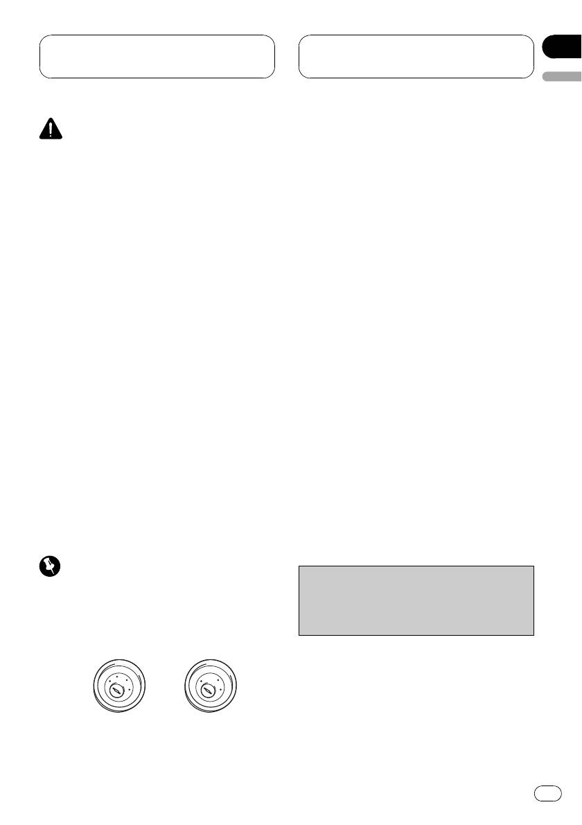
! When this unit is installed in a vehicle without
duct, even if cord color is the same. When con-
ACC (accessory) position on the ignition
necting this system, be sure to check all
switch, red cable must be wired to the term-
manuals and connect cords correctly.
inal that can detect the operation of the igni-
tion key. Otherwise, battery drain may result.
A
C
C
F
O
F
N
O
F
F
N
O
S
O
S
T
T
A
A
R
R
T
T
ACC posi-
No ACC po-
tion
sition
11
En


