Yamaha RX-V663 Black: Troubleshooting
Troubleshooting: Yamaha RX-V663 Black
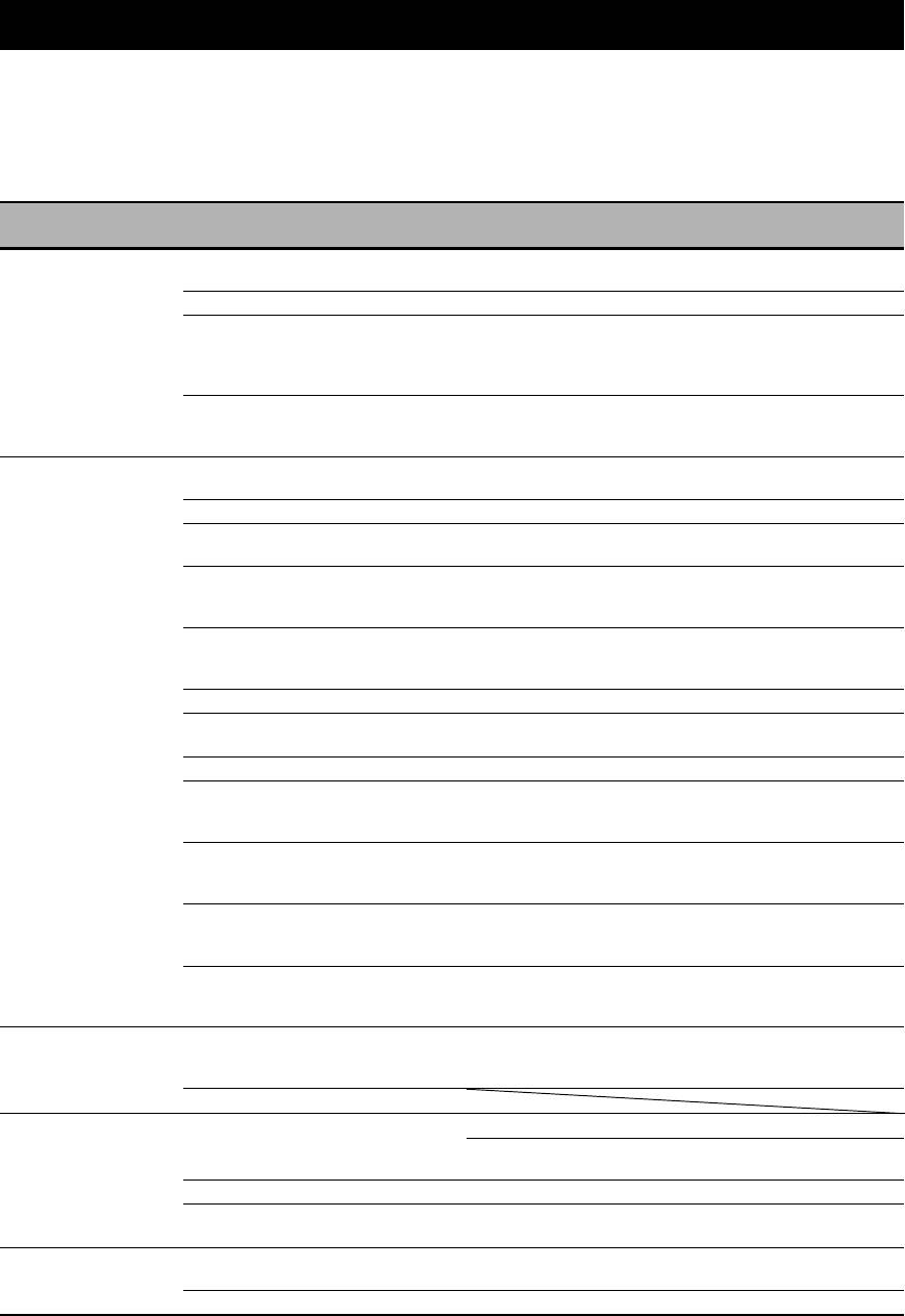
TROUBLESHOOTING
Troubleshooting
Refer to the table below when this unit does not function properly. If the problem you are experiencing is not listed below
or if the instruction below does not help, turn off this unit, disconnect the power cable, and contact the nearest authorized
Yamaha dealer or service center.
■ General
See
Problem Cause Remedy
page
This unit fails to turn
The power cable is not connected or the
Connect the power cable firmly. —
on or enters the
plug is not completely inserted.
standby mode soon
The speaker impedance setting is incorrect. Set the speaker impedance to match your speakers. 28
after the power is
The protection circuitry has been activated. Make sure that all speaker wire connections on this
14
turned on.
unit and on all speakers are secure and that the wires
for each connection do not touch anything other than
their respective connections.
This unit has been exposed to a strong
Set this unit to the standby mode, disconnect the power
—
external electric shock (such as lightning or
cable, plug it back in after 30 seconds and then use this
strong static electricity).
unit normally.
No sound. Incorrect input or output cable connections. Connect the cables properly. If the problem persists,
20-26
the cables may be defective.
The optimizer microphone is connected. Disconnect the optimizer microphone. 35
Audio input jack select is set to “HDMI”,
Set Audio input jack select to “AUTO”. 44
“COAX/OPT” or “ANALOG”.
Audio input jack select is set to
Set Audio input jack select to “AUTO” or
44
“ANALOG” while playing a source
“COAX/OPT”.
encoded in Dolby Digital or DTS.
No appropriate input source has been
Select an appropriate input source with the INPUT
42, 43
selected.
selector on the front panel (or the input selector
buttons on the remote control).
Speaker connections are not secure. Secure the connections. 14
The front speakers to be used have not been
Select the front speakers by pressing
A
SPEAKERS
43
selected properly.
on the front panel repeatedly.
The volume is turned down. Turn up the volume. —
The sound is muted.
Press
G
MUTE or
G
VOLUME +/– on the remote
45
control to resume audio output and then adjust the
volume.
Signals this unit cannot reproduce are
Play a source whose signals can be reproduced by this
—
being input from a source component, such
unit.
as a CD-ROM.
The HDMI components connected to this
Connect HDMI components that support the HDCP
18
unit do not support the HDCP copy
copy protection standards.
protection standards.
“S.AUDIO” is set to “OTHER” and
Set “S.AUDIO” to “RX-V663” in “MANUAL
89
“HDMI” audio signals are not being played
SETUP”.
back on this unit.
No picture. The output and input for the picture are
Set “VIDEO CONV.” to “ON” or connect your source
88
connected to different types of video jacks.
components in the same way as you connect your
video monitor to this unit.
Non-standard video signals are input.
The sound suddenly
The protection circuitry has been activated
Check that the speaker impedance setting is correct. 28, 106
goes off.
because of a short circuit, etc.
Check that the speaker wires are not touching each
—
other and then turn this unit back on.
The sleep timer has turned this unit off. Turn this unit on, and play the source again. —
The sound is muted.
Press
G
MUTE or
G
VOLUME +/– on the remote
45
control to resume audio output.
Sound is heard from
Incorrect cable connections. Connect the cables properly. If the problem persists,
14
the speaker on one
the cables may be defective.
side only.
Incorrect settings in “SP LEVEL”. Adjust the “SP LEVEL” settings. 78
110 En

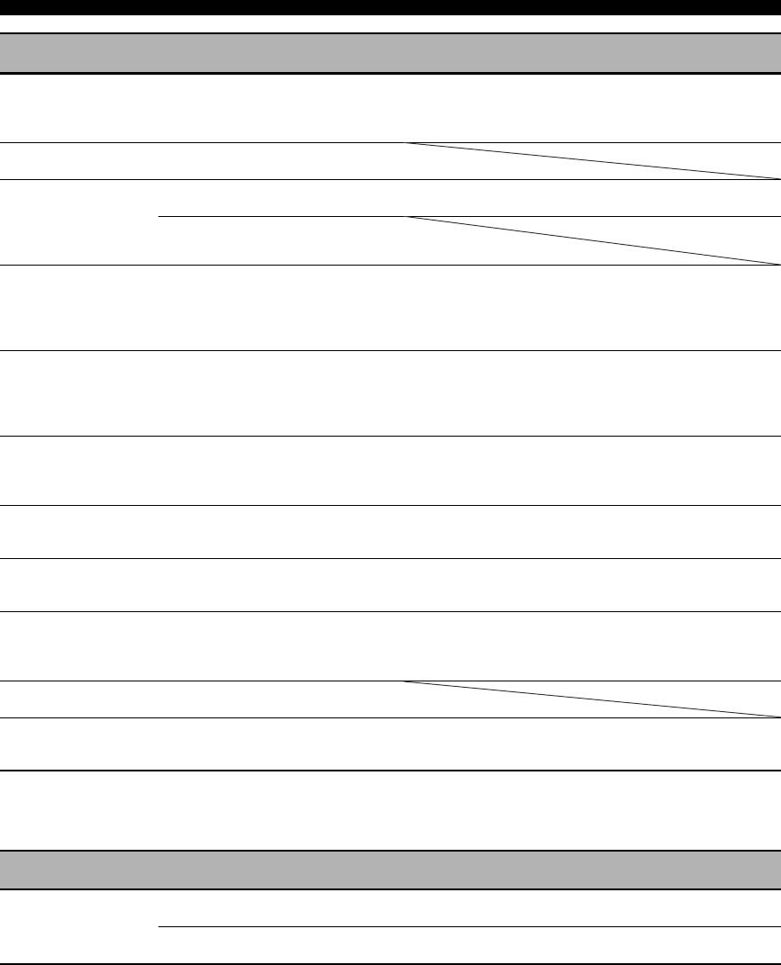
Troubleshooting
See
Problem Cause Remedy
page
Only the center
When playing a monaural source with a
speaker outputs
sound field program, the source signal is
substantial sound.
directed to the center channel, and the front
and surround speakers output effect
sounds.
No sound is heard
“CENTER SP” in “SET MENU” is set to
Set “CENTER SP” to “SMALL” or “LARGE”. 77
from the center
“NONE”.
speaker.
One of the sound field programs (except
Try another sound field program. 48
for “7ch Stereo”) has been selected.
No sound is heard
The sound field programs are turned off.
Press
O
STRAIGHT to turn them on.
51
from the presence
You are using a source or program
Try another sound field program. 42
speakers.
combination that does not output sound
from all channels.
“EXTRA SP ASSIGN” is set to a setting
Set “EXTRA SP ASSIGN” to “PRESENCE”. 76
other than “PRESENCE”.
No sound is heard
“SUR. L/R SP” in “SET MENU” is set to
Set “SUR. L/R SP” to “SML” or “LRG”. 77
from the surround
“NONE”.
speakers.
This unit is in the “Straight” mode and a
Press
O
STRAIGHT on the front panel so that
51
monaural source is being played back.
“Straight” disappears from the front panel display.
No sound is heard
“SUR. L/R SP” in “SET MENU” is set to
Set “SUR. L/R SP” and “SUR.B L/R SP” to a setting
77
from the surround
“NONE” and “SUR.B L/R SP” is
other than “NONE”.
back speakers.
automatically set to “NONE”.
“SUR.B L/R SP” in “SET MENU” is set to
Set “SUR.B L/R SP” to a setting other than “NONE”. 77
“NONE”.
Zone 2 speaker
“EXTRA SP ASSIGN” is set to a setting
Set “EXTRA SP ASSIGN” to “ZONE2”. 76
settings are not
other than “ZONE2”.
available in “SET
MENU”.
FRONT B speakers
“EXTRA SP ASSIGN” is set to a setting
Set “EXTRA SP ASSIGN” to “FRONT B”. 76
cannot be activated.
other than “FRONT B”.
No sound from the
“EXTRA SP ASSIGN” is set to
Set “EXTRA SP ASSIGN” to “FRONT B”. 76
center, surround or
“ZONE B”.
surround back
speakers when the
FRONT B speakers are
activated.
INFORMATION
ADDITIONAL
Presence speaker
“EXTRA SP ASSIGN” is set to a setting
Set “EXTRA SP ASSIGN” to “PRESENCE”. 76
settings are not
other than “PRESENCE”.
available in “SET
MENU”.
No sound is heard
“LFE/BASS OUT” in “SET MENU” is set
Set “LFE/BASS OUT” to “SWFR” or “BOTH”. 76
from the subwoofer.
to “FRONT” when a Dolby Digital or DTS
signal is being played.
“LFE/BASS OUT” in “SET MENU” is set
Set “LFE/BASS OUT” to “BOTH”. 76
to “SWFR” or “FRONT” when a
2-channel source is being played.
The source does not contain low-frequency
signals.
Dolby Digital or DTS
The connected component is not set to
Make an appropriate setting following the operating
—
sources cannot be
output Dolby Digital or DTS digital
instructions for your component.
played. (Dolby Digital
signals.
or DTS indicator in the
Audio input jack select is set to
Set Audio input jack select to “AUTO”. 44
front panel display
“ANALOG”.
does not light up.)
A humming sound is
Incorrect cable connections. Connect the audio cables firmly. If the problem
—
heard.
persists, the cables may be defective.
No connection from the turntable to the
Connect the grounding cable of your turntable to the
23
GND terminal.
GND terminal of this unit.
English
The volume level is
The record is being played on a turntable
Connect your turntable to this unit through an MC-
23
low while a record is
with an MC cartridge.
head amplifier.
being played.
111 En
Troubleshooting
See
Problem Cause Remedy
page
The volume level
The component connected to the AUDIO
Turn on the power of the component. —
cannot be increased,
OUT (REC) jacks of this unit is turned off.
or the sound is
distorted.
The sound effects
It is not possible to record the sound effects
cannot be recorded.
with a recording component.
A source cannot be
The source component is not connected to
Connect the source component to the DIGITAL
21, 23
recorded by a digital
the DIGITAL INPUT jacks of this unit.
INPUT jacks.
recording component
Some components cannot record Dolby
connected to the
Digital or DTS sources.
DIGITAL OUTPUT jack.
A source cannot be
The source component is not connected to
Connect the source component to the analog AUDIO
23
recorded by an analog
the analog AUDIO IN jacks of this unit.
IN jacks.
component connected
to the AUDIO OUT
(REC) jacks.
The sound field
“MEMORY GUARD” in “SET MENU” is
Set “MEMORY GUARD” to “OFF”. 88
parameters and some
set to “ON”.
other settings of this
unit cannot be
changed.
This unit does not
The internal microcomputer has been
Disconnect the power cable from the AC wall outlet
—
operate properly.
frozen by an external electric shock (such
and then plug it in again after about 30 seconds.
as lightning or excessive static electricity)
or by a power supply with low voltage.
No sound is heard
The HDMI component does not accept the
Convert the multi-channel audio signals to the
—
from the connected
multi-channel audio signals.
2-channel audio signals at the source component such
HDMI component.
as a DVD player.
“CHECK SP WIRES”
Speaker cables are short-circuited. Make sure all speaker cables are connected correctly. 14
appears in the front
panel display.
There is noise
This unit is too close to the digital or high-
Move this unit further away from such equipment. —
interference from
frequency equipment.
digital or radio
frequency equipment.
The picture is
The video source uses scrambled or
disturbed.
encoded signals to prevent dubbing.
This unit suddenly
The internal temperature is too high and the
Wait about 1 hour for this unit to cool down and then
—
enters the standby
overheat protection circuitry has been
turn it back on.
mode.
activated.
■ HDMI
See
Problem Cause Remedy
page
No picture or sound.
The number of the connected HDMI
Reduce the number of the connected HDMI
—
components is over the limit.
components.
HDCP authentication failed. Check that the connected HDMI components support
—
the HDCP copy protection standards.
112 En
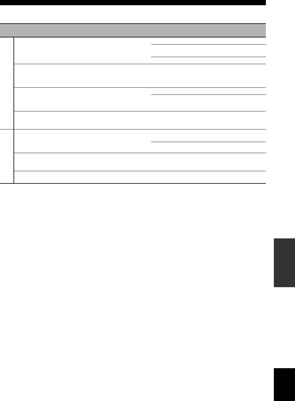
Troubleshooting
■ Tuner (FM/AM)
See
Problem Cause Remedy
page
FM stereo reception is
The characteristics of FM stereo
Check the antenna connections. 27
noisy.
broadcasts may cause this problem
Try using a high-quality directional FM
—
when the transmitter is too far away or
antenna.
the antenna input is poor.
Use the manual tuning method. 53
There is distortion, and
There is multi-path interference. Adjust the antenna position to eliminate multi-
—
clear reception cannot be
path interference.
obtained even with a
FM
good FM antenna.
The desired station
The signal is too weak. Use a high-quality directional FM antenna. —
cannot be tuned into with
Use the manual tuning method. 53
the automatic tuning
method.
Previously preset
This unit has been disconnected for a
Preset the stations again. 54
stations can no longer be
long period.
tuned into.
The desired station
The signal is weak or the antenna
Tighten the AM loop antenna connections and
—
cannot be tuned into with
connections are loose.
orient the antenna for the best reception.
the automatic tuning
Use the manual tuning method. 53
method.
AM
There are continuous
Noise can result from lightning,
Use an outdoor antenna and a ground wire.
—
crackling and hissing
fluorescent lamps, motors, thermostats
This will help somewhat, but it is difficult to
noises.
and other electrical equipment.
eliminate all noise.
There are buzzing and
A TV set is being used nearby. Move this unit away from the TV set. —
whining noises.
INFORMATION
ADDITIONAL
English
113 En
Troubleshooting
■ Remote control
See
Problem Cause Remedy
page
The remote control
Wrong distance or angle. The remote control will function within a maximum
31
does not work or
range of 6 m and no more than 30 degrees off-axis
function properly.
from the front panel.
Direct sunlight or lighting (from an
Reposition this unit. —
inverter type of fluorescent lamp, etc.) is
striking the remote control sensor of this
unit.
The batteries are weak. Replace all batteries. 4
The operation mode selector is set
Set the operation mode selector correctly.
—
incorrectly.
When operating this unit, set it to the
F
AMP
position. When operating the component selected by
the input selector button, set it to the
F
SOURCE
position. When operating the TV set in the
5
DTV/CBL or
5
PHONO area, set it to the
F
TV
position.
The remote control code was not correctly
Set the remote control code correctly using
93
set.
“List of remote control codes” at the end of this
manual.
Try setting another code of the same manufacturer
93
using “List of remote control codes” at the end of this
manual.
The library code of the remote control and
Match the remote control ID of this unit with the
107, 108
the remote control ID of this unit do not
corresponding remote control library code.
match.
Even if the remote control code is
Program the necessary functions independently into
95
correctly set, there are some models that
the programmable buttons using the Learn feature.
do not respond to the remote control.
The remote control
The batteries of this remote control and/or
Replace the batteries. 4
does not learn new
the other remote control are too weak.
functions.
The distance between the two remote
Place the remote controls at the proper distance. 95
controls is too much or too little.
The signal coding or modulation of the
Learning is not possible. —
other remote control is not compatible
with this remote control.
Memory capacity is full. Delete other unnecessary functions to make room for
101
the new functions.
114 En
Troubleshooting
■ iPod
Note
In case of a transmission error without a status message appearing in the front panel and in the OSD, check the connection to your iPod
(see page 25).
See
Status message Cause Remedy
page
Loading...
This unit is in the middle of recognizing the
connection with your iPod.
This unit is in the middle of acquiring song
lists from your iPod.
Connect error
There is a problem with the signal path
Turn off this unit and reconnect the Yamaha iPod
25
from your iPod to this unit.
universal dock to the DOCK terminal of this unit.
Try resetting your iPod. —
Unknown iPod
The iPod being used is not supported by
Only iPod (Click and Wheel), iPod nano, and iPod
—
this unit.
mini are supported.
iPod connected
Your iPod is properly stationed in a
Yamaha iPod universal dock (such as YDS-
10, sold separately) connected to the
DOCK terminal of this unit, and the
connection between your iPod and this unit
is complete.
Disconnected
Your iPod was removed from a Yamaha
Station your iPod back in a Yamaha iPod universal
25
iPod universal dock (such as YDS-10 sold
dock (such as YDS-10 sold separately) connected to
separately) connected to the DOCK
the DOCK terminal of this unit.
terminal of this unit.
Unable to play
This unit cannot play back the songs
Check that the songs currently stored on your iPod are
—
currently stored on your iPod.
playable.
Store some other playable music files on your iPod. —
■ Bluetooth
See
Status message Cause Remedy
page
Searching...
The Bluetooth adapter and the Bluetooth
INFORMATION
component is in the middle of the pairing.
ADDITIONAL
The Bluetooth adapter and the Bluetooth
component is in the middle of establishing
the connection.
Completed
The paring is completed.
Canceled
The paring is canceled.
BT connected
The connection between the Yamaha
Bluetooth adapter (such as YBA-10, sold
separately) and the Bluetooth component is
established.
Disconnected
The Bluetooth component is disconnected
from the Yamaha Bluetooth adapter (such
as YBA-10, sold separately).
No BT adapter
The Bluetooth adapter is not connected to
Connect the Yamaha Bluetooth adapter (such as YBA-
25
the DOCK terminal.
10, sold separately) to the DOCK terminal.
Not found
Yamaha Bluetooth adapter (such as YBA-
10, sold separately) could not find any
Bluetooth components.
Not Available
Another Bluetooth connection has already
Terminate the existing connection. 62
been established.
English
115 En
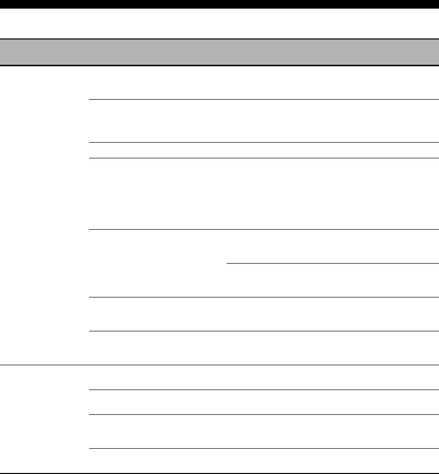
Troubleshooting
■ AUTO SETUP
Before AUTO SETUP
See
Error message Cause Remedy
page
Connect MIC!
Optimizer microphone is not connected. Connect the supplied optimizer microphone
32
to the OPTIMIZER MIC jack on the front
panel.
Unplug HP!
Headphones are connected. Unplug the headphones. —
Memory Guard!
The parameters of this unit are protected. Set “MEMORY GUARD” to “OFF”. 88
During AUTO SETUP
See
Error message Cause Remedy
page
E-1:NO FRONT SP
Front L/R channel signals are not detected. Check the front L/R speaker connections. 14
E-2:NO SUR SP
A surround channel signal is not detected. Check the surround speaker connections. 14
E-3:NO PRNS SP
A presence channel signal is not detected. Check the presence speaker connections. 14
E-4:SBR->SBL
Only a right surround back channel signal is
Connect the surround back speaker to the
14
detected.
LEFT SURROUND BACK SPEAKERS
terminal if you only have one surround back
speaker.
E-5:NOISY
Background noise is too loud. Try running “AUTO SETUP” in a quiet
—
environment.
Turn off noisy electric equipment like air
—
conditioners or move them away from the
optimizer microphone.
E-6:CHECK SUR.
Surround back speakers are connected,
Connect surround speakers when you use
14
though surround L/R speakers are not.
surround back speakers.
E-7:NO MIC
The optimizer microphone was unplugged
Connect the supplied optimizer microphone
32
during the “AUTO SETUP” procedure.
to the OPTIMIZER MIC jack on the front
panel.
E-8:NO SIGNAL
The optimizer microphone does not detect
Check the microphone setting. 32
test tones.
Check the speaker connections and
14
placement.
E-9:USER CANCEL
The “AUTO SETUP” procedure was
Run “AUTO SETUP” again. 32
cancelled due to user activity.
E-10:INTERNAL ERROR
An internal error occurred. Run “AUTO SETUP” again. 32
116 En

Troubleshooting
After AUTO SETUP
See
Warning message Cause Remedy
page
W-1:OUT OF PHASE
Speaker polarity is not correct. This message
Check the speaker connections for proper
14
may appear depending on the speakers even
polarity (+ or –).
when the speakers are connected correctly.
W-2:OVER 24m (80ft)
The distance between the speaker and the
Bring the speaker closer to the listening
—
listening position is over 24 m (80 ft).
position.
W-3:LEVEL ERROR
The difference of volume level among
Readjust the speaker installation so that all
—
speakers is excessive.
speakers are set in locations with similar
conditions.
Check the speaker connections. 14
Use speakers of similar quality. —
When “SWFR: TOO LOUD” or “SWFR:
32
TOO LOW” appears in the result screen, the
output volume of the subwoofer.
W-4:CHECK PRNS
“EXTRA SP ASSIGN” is set to
Check the presence speaker connections. 14
“PRESENCE”, though the presence channel
Set “EXTRA SP ASSIGN” to a setting other
33
signals are not detected.
than “PRESENCE”.
Notes
• If the “ERROR” or “WARNING” screens appears, check the cause of the problem, then run “AUTO SETUP” again.
• If a warning message “W-1”, “W-2”, or “W-3” appears, corrections are made, but they may not be optimal.
• If an error message “E-10” occurs repeatedly, contact a qualified Yamaha service center.
INFORMATION
ADDITIONAL
English
117 En
Оглавление
- Caution: Read this before operating your unit.
- Contents
- Features
- Notice
- Getting started
- Quick start guide
- Connections
- Optimizing the speaker setting for your listening room (YPAO)
- Selecting the SCENE templates
- Playback
- Sound field programs
- Using audio features
- FM/AM tuning
- Radio Data System tuning (Europe and Russia models only)
- Using iPod™
- Using Bluetooth™ components
- Recording
- Advanced sound configurations
- Customizing this unit (MANUAL SETUP)
- Remote control features
- Using multi-zone configuration
- Advanced setup
- Troubleshooting
- Resetting the system
- Glossary
- Sound field program information
- Specifications
- Index
- Предупреждение: Внимательно изучите это перед использованием аппарата.
- Содержание
- Описание
- Уведомление
- Начало работы
- Краткое руководство пользователя
- Подключения
- Оптимизация настройки колонок для комнаты для прослушивания (YPAO)
- Выборе шаблонов SCENE
- Воспроизведение
- Программы звукового поля
- Использование аудиофункций
- Настройка радиопрограмм диапазона ЧМ/AM
- Функция настройки Системы Радиоданных (Только модели для Европы и России)
- Использование iPod™
- Использование компонентов Bluetooth™
- Запись
- Дополнительные конфигурации звучания
- Настройка данного аппарата (MANUAL SETUP)
- Функции пульта ДУ
- Использование многозонной конфигурации
- Дополнительные настройки
- Возможные неисправности и способы по их устранению
- Перезагрузка системы
- Справочник
- Информация программы звукового поля
- Технические характеристики
- Предметный указател


